US851663A - Electromagnet. - Google Patents
Electromagnet. Download PDFInfo
- Publication number
- US851663A US851663A US25363805A US1905253638A US851663A US 851663 A US851663 A US 851663A US 25363805 A US25363805 A US 25363805A US 1905253638 A US1905253638 A US 1905253638A US 851663 A US851663 A US 851663A
- Authority
- US
- United States
- Prior art keywords
- core
- parts
- legs
- electro
- magnet
- Prior art date
- Legal status (The legal status is an assumption and is not a legal conclusion. Google has not performed a legal analysis and makes no representation as to the accuracy of the status listed.)
- Expired - Lifetime
Links
Images
Classifications
-
- H—ELECTRICITY
- H01—ELECTRIC ELEMENTS
- H01F—MAGNETS; INDUCTANCES; TRANSFORMERS; SELECTION OF MATERIALS FOR THEIR MAGNETIC PROPERTIES
- H01F7/00—Magnets
- H01F7/06—Electromagnets; Actuators including electromagnets
- H01F7/08—Electromagnets; Actuators including electromagnets with armatures
- H01F7/16—Rectilinearly-movable armatures
- H01F7/1607—Armatures entering the winding
Definitions
- WITNESSES I IgVENTOR a 77) @flo 6.6M ATTORNEY l be rendere RAY P. JACKSON, OF WILKINSBURG, PENNSYLVANIA, ASSIGNOR' TO WEST-' INGHOUSE ELECTRIC & MANUFACTURING COMPANY, A CORPORATION OF PENNSYLVANIA.
- My invention relates to e ectro-magnets and particularly to such as are operated by 1o alternating currents.
- the object of my invention is to provide a novel and improved structure for electromagnets by means Of'Wl'LlCll vibration between the arts of the magnet core may (i so slight as to be unobjectionable.
- Electro-magnets which have heretofore been constructed for operation by singlephase' alternating currents have embodied 2o armatures or core sections that were movable against gravity or springs and consequ'ently, each time the alternating current electro-motive force passed through its zero value the parts of the magnet core would 2 5 separate and would be again brought together as, the currentrose to its maximum value. Vibration of this character is prohibited in certain classes of work while the 9 noise due to vibration is generally objection- 0 able in all classes of work.
- My invention provides an electro-magnet the parts of which are so constructed and arranged that the vibration may be greatly reduced or actually prevented and the noise due to vibration may be rendered almost unnoticeable.
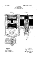
- FIG. 1' is a view in side elevation of an electro-magnet, constructed in accordance therewith, the inclosing casing and certain of the other parts being shown in section
- Fig. 2 is a view in end elevation of the electro-magnet shown in Fig. 1 removed from its inclosing casing.
- the magnetizable core of the electromagnet comprises two sections, 1 and 2 that are composed of U-shaped laminae the uper legs 3 of which are wider than the lower legs 4.
- the laminae are clamped, by means of rivets 5, between side plates 6 that are provided with ear portions 7 and 8 which roject from'the outer-sides of the lower P egs 4.
- the U-sha ed sections of the core are su ported in as releton frame work 9 with t e planes of the laminae vertical, by means of pivot pins 10 and 11 that pass through the ear portions 7 and 8 and the lower ends of the frame Work 9.
- the axes of the pivot pins may be located either vertically below the centers of gravity of the U-sha ed sections or nearer the central plane of t e mag net, in order that the upper legs 3 may be moved apart by gravity, when the core is not magnetized, as indicated in Fig. 1.
- a magnetizing winding 12 is mounted upon an insulating spool 13 that surrounds the upper legs 3 of the core sections and is supported inposition by means of bolts 14 and bent up portions 15 of the frame work 9.
- the ends of the ear portions 7 and 8 may be provided with slightly elongated apertures 16 in which may be located a pin 17 that also passes throu h an eye 18 at the uper end of a valve rod 19, having a tapered ower end.
- the rod 19 operates in a guide rovided by a screw threaded projection 20 irom the bottom of an inclosing casing 21 to which the frame work 9 is secured by means of pins 22.
- the screw threaded projection 20 engages corresponding screw threads in a member having inlet, supply and, exhaust chambers 23, 241 and 25, respectively, and correspondmg communicating passages 26, 27 and 28.
- a bushing 29 Located in apertures in the partition walls of the chambers is a bushing 29 having lateral apertures '30 that open into the chamber 24 and concave valve seats 31 and 32 in its upper and lower ends for the reception, res ectively, of the lower conical end of the ro 19 and of a conical flange 33 v upon a rod 34 that is carried by the rod 19.
- my invention may be supplemented by another means for obviating or reducing vibration between the arts of the magnet core which effects dispacement of the phase of a portion of the flux between the magnet pole pieces with res 'ect, to the remainder of the flu so that the reversals of polarity of the two portions of the llux shall.
- Such means may comprise loops 36 of conducting material surrounding portions of the pole-pieces of the magnet, the portions 37 of the pole pieces which are surrounded; by the conducting structures being preferably longer than the remaining portions 38 in order that an ap limbate amount of flux may be forced through the conducting loops when the two portions of the core are in engagement.
- T his supplementary means was not invented by me and it is notessential to satisfactory operation of magnets that have the structural features hereinbefore described but practical experience"hasdemonstrated that the loops 36 assist in reducing'thehum due to the alternations of the magnetism to unobjectionable proportions.
- the magnet may be.- invertedsothat the pivotal supports for the core parts shall be above the centers of gravity thereof, though in such case they will preferably be located outside of vertical lines through'the centers of gravity in order that when the parts are demagnetized they may be-separated automatically by gravity. All other variations from what is shown, as re gards the positions of the magnet members, which do not materially change the mode of operation or result, are to be considered as within the scope of my invention.
- an operative structure might be ado ted in'which one of the core sections W0 (1 be rigidly supported and the other section be either pivotally orotherwisemovably supported so as to act in accordance with the desired conditions.
- the shapes of the core sections and of the projecting ear portions or levers carried thereby, as well as many other of the details of construction and arrangements of the parts, may also be varied considerably from what is specifically shown and described without departing from my invention.
- the magnet comprising my invention there are no armatures or other weights which are entirely supported against gravity or springs by the magnetizing action exerted by the winding, and that as a result the forces tending to effect separation of the parts of the core when the magnetism reverses its polarity are greatly reduced as compared with the corresponding forces in electromagnets which have heretofore been employed.
- the movable parts are pivotally supported in unstable equilibrium and the magnetizing force required to effect operation of the parts of the core and maintain them in engagement may be very small as compared with that which may be necessary to raise an armature or a movable part of the core against the attraction of gravity.
- the movable core sections may be supported upon pivots that are located either above or below their centers of gravity provided the pivots are so lo cated that gravity will move the sections apart when they are demagnetized but will be overcome by a very small magnetic pull.
- a core structure for electro-magnets comprising two U-shaped parts, a pivotal connection between the parts, and pivotal supports for the parts located between and below the centers of gravitythereof'.
- a core structure for electro-maghets comprising twoEU-shaped parts and independent pivotal supports tor the parts located between and below the centers of gravity thereof.
- a core structure for electro-magnets supports for the parts located below the centers of gravity thereof.
- a core structure for electro-magnets comprising two U-shaped parts, a pivotal connection between the parts, and pivotal supports for the parts.
- a core structure for el'ectro-magnets comprising two U-shaped parts, a pivotal connection between the parts, pivotal supports for the parts, and a member operated by the pivotal connection between the parts.
- a core structure for electro-magnets comprising two U-shaped magnetizable parts both of'which are freely movable by magnetism and gravity and a pivotal connection between the parts.
- a core structure for electro-magnets comprising two U-shaped magnetizable parts at least one of which is pivotally supported to be freely movable in one direction by magnetism and in the other direction by gravity.
- a core structure for electro-magnets comprising two U-shaped magnetizable parts one leg of each U-shaped part being of greater mass than the other leg and a pivotal support for one of the parts.
- a core structure for electro-magnets comprising two U-shaped magnetizable parts, one leg of each U-shaped part being of greater mass than the other leg and a pivotal support for one of the parts located below the center of gravity thereof.
- An electro-magnet comprising two U- shaped magnetizable core parts two of the legs of which are pivoted to ether and a winding surrounding the two egs that are remote from the pivot.
- An electro-magnet comprising two U- shaped magnetizable core parts, a pivotal support for one of said parts and a stationary winding surrounding two 'of the legs of said parts.
- An electro-magnet comprising two U- shaped core parts one leg of each of which is of greater mass than the other, a pivotal support for one of said parts and a winding surrounding the legs of greater mass.
- An electro-magnet comprising two U shaped, magnetizable cores, a pivotal connection between the cores, and a stationary winding surrounding two of the legs of the cores.
- An electro-nirgnet comprising two U- shaped, magnetizable cores, a pivotal connection between two of the legs of the cores, and a winding surrounding the other two legs only, of the cores.
- a core structure for electro-magnets comprising two U-shaped parts the legs of which have opposing faces and a pivotal support for one of the parts located below'the center of ravity thereof, the mostwidely separable egs of the core being of greater mass than the other legs.
- a "core structure for electro-magnets ing surrounding the upper legs of the core comprising two U-shaped parts the legs of which have opposing faces and a pivotal support for one of the parts, the most widely separable legs of the core being of greater mass than the other legs.
- a core structure for electro-magnets comprising two U-shaped parts the legs of which have opposing faces, a pivotal support for one of the parts, the most widely separa ble legs of the core being of greater mass than the other legs and a winding surrounding the legs of greater mass.
- An electro-magnet comprising two U- shaped, magnetizable core sections having approximately horizontal legs the upper ones of which are of greater mass than the lower ones, and a pivotal support for one of the core sections located below the center of gravity thereof.
- An electro-magnet comprising two U- shaped, magnetizable core sections having approximately horizontal legs, a pivotal support for one of the core sections located below the center of gravity thereof, and a windsections.
- An electro-magnet comprising two U- shaped, magnetizable core sections having approximately horizontal legs the upper ones of which are of greater mass than the lower ones, a pivotal support for one of the core sections located below the center of gravity thereof, and a winding surrounding the up per legs of'the core sections.
- An electro-magnet comprising two U- shaped, magnetizable core sections having approximately horizontal legs, a pivotal connection between two of the legs of the coresections, and a stationary coil surrounding the other two legs of the core sections.
- An electro-magnet comprising two U- shaped, magnetizable core sections having approximately horizontal legs, a pivotal connection between two of the legs of the core 7 sections, and a winding surrounding the other legs only of the core sections.
- An electro-magnet comprising two U- shaped, magnetizable core sections having approximately horizontal legs two of which are of greater mass than the others and a pivotal connection between the legs of lesser mass.
- An electro-magnet comprising two U-' shaped, magnetizable core sections having approximately horizontal legs two of which are of greater mass than the others, a pivotal connection between the legs of lesser mass and a winding surrounding the other legs of the core sections.
- An electro-magnet having a single coil 125 and two movable core sections therefor that are pivotally supported to move apart when demagnetized and be drawn and held together by a slight magnetic pull.
- An electro-lnagnet having a single coil I30 and two core sections that are niovably supported below their centers of grm'ity and are maintained in unstable equilibrium when riuni when magnetized.
Landscapes
- Physics & Mathematics (AREA)
- Electromagnetism (AREA)
- Engineering & Computer Science (AREA)
- Power Engineering (AREA)
- Electromagnets (AREA)
Description
No. 851,663. PATENTED APR. so, 1907.
R. P. JACKSON.
ELEGTROMAGNET.
APPLICATION FILED APB..3. 1905.
WITNESSES: I IgVENTOR a 77) @flo 6.6M ATTORNEY l be rendere RAY P. JACKSON, OF WILKINSBURG, PENNSYLVANIA, ASSIGNOR' TO WEST-' INGHOUSE ELECTRIC & MANUFACTURING COMPANY, A CORPORATION OF PENNSYLVANIA.
ELEOTROMAGNET.
1 Specification of Letters Patent.
Patented April 30, 19 07 Application filed April 3.190s. Serial No. 253,638.
To. all whom it may concern.-
Be it known that I, RAY P. JAoKsoN, a citizen of the United States, and a resident of Wilkinsburg, in the county of Allegheny and 5 State of Pennsylvania, have invented a new and useful Im rovement in Electromagnets,
of which the ollowing is a s ecification.
My invention relates to e ectro-magnets and particularly to such as are operated by 1o alternating currents.
The object of my invention is to provide a novel and improved structure for electromagnets by means Of'Wl'LlCll vibration between the arts of the magnet core may (i so slight as to be unobjectionable.
Electro-magnets which have heretofore been constructed for operation by singlephase' alternating currents have embodied 2o armatures or core sections that were movable against gravity or springs and consequ'ently, each time the alternating current electro-motive force passed through its zero value the parts of the magnet core would 2 5 separate and would be again brought together as, the currentrose to its maximum value. Vibration of this character is prohibited in certain classes of work while the 9 noise due to vibration is generally objection- 0 able in all classes of work.
My invention provides an electro-magnet the parts of which are so constructed and arranged that the vibration may be greatly reduced or actually prevented and the noise due to vibration may be rendered almost unnoticeable.
Mv invention is illustrated in the accom-- panying drawing in whi ch Figure 1' is a view in side elevation of an electro-magnet, constructed in accordance therewith, the inclosing casing and certain of the other parts being shown in section, and Fig. 2 is a view in end elevation of the electro-magnet shown in Fig. 1 removed from its inclosing casing.
The magnetizable core of the electromagnet comprises two sections, 1 and 2 that are composed of U-shaped laminae the uper legs 3 of which are wider than the lower legs 4. The laminae are clamped, by means of rivets 5, between side plates 6 that are provided with ear portions 7 and 8 which roject from'the outer-sides of the lower P egs 4.
V The U-sha ed sections of the core are su ported in as releton frame work 9 with t e planes of the laminae vertical, by means of pivot pins 10 and 11 that pass through the ear portions 7 and 8 and the lower ends of the frame Work 9. The axes of the pivot pins may be located either vertically below the centers of gravity of the U-sha ed sections or nearer the central plane of t e mag net, in order that the upper legs 3 may be moved apart by gravity, when the core is not magnetized, as indicated in Fig. 1.
A magnetizing winding 12 is mounted upon an insulating spool 13 that surrounds the upper legs 3 of the core sections and is supported inposition by means of bolts 14 and bent up portions 15 of the frame work 9.
For the purpose of illustrating the utility of my invention I have shown it as ap lied to the operation of pneumatic va ves, though it is, of course, understood'that it may be employed for manvother purposes.
The ends of the ear portions 7 and 8 may be provided with slightly elongated apertures 16 in which may be located a pin 17 that also passes throu h an eye 18 at the uper end of a valve rod 19, having a tapered ower end. The rod 19 operates in a guide rovided by a screw threaded projection 20 irom the bottom of an inclosing casing 21 to which the frame work 9 is secured by means of pins 22.
The screw threaded projection 20 engages corresponding screw threads in a member having inlet, supply and, exhaust chambers 23, 241 and 25, respectively, and correspondmg communicating passages 26, 27 and 28. Located in apertures in the partition walls of the chambers is a bushing 29 having lateral apertures '30 that open into the chamber 24 and concave valve seats 31 and 32 in its upper and lower ends for the reception, res ectively, of the lower conical end of the ro 19 and of a conical flange 33 v upon a rod 34 that is carried by the rod 19. When the magnet winding is not energized, the flange 33 is nor- .mally maintained in engagement with the corresponding valveseat 32 by means' of a spring 35 and passage of fluid is thereby prevented from the inlet chamber 23 to the supply chamber 24. When the two ortions 3 of the core are drawn together, t e conical end of the rod 19 is forced downwardly-into engagement with the valve seat 31 and the I 525- causes I 35, the pivotal connection thereof wit the ear portions 7 and 8 may be omitted, if desired, and theupper end of the rod 19 may simply rest against properly shaped overlapping car portions that are formed integral wit the side plates 6. r
if desired, my invention may be supplemented by another means for obviating or reducing vibration between the arts of the magnet core which effects dispacement of the phase of a portion of the flux between the magnet pole pieces with res 'ect, to the remainder of the flu so that the reversals of polarity of the two portions of the llux shall.
occur dissimultaneously. Such means may comprise loops 36 of conducting material surrounding portions of the pole-pieces of the magnet, the portions 37 of the pole pieces which are surrounded; by the conducting structures being preferably longer than the remaining portions 38 in order that an ap propriate amount of flux may be forced through the conducting loops when the two portions of the core are in engagement. T his supplementary means was not invented by me and it is notessential to satisfactory operation of magnets that have the structural features hereinbefore described but practical experience"hasdemonstrated that the loops 36 assist in reducing'thehum due to the alternations of the magnetism to unobjectionable proportions.
lit will be understood that the magnet may be.- invertedsothat the pivotal supports for the core parts shall be above the centers of gravity thereof, though in such case they will preferably be located outside of vertical lines through'the centers of gravity in order that when the parts are demagnetized they may be-separated automatically by gravity. All other variations from what is shown, as re gards the positions of the magnet members, which do not materially change the mode of operation or result, are to be considered as within the scope of my invention.
While I haveshown both sections of the magnet core as movable and pivotally supported, an operative structure might be ado ted in'which one of the core sections W0 (1 be rigidly supported and the other section be either pivotally orotherwisemovably supported so as to act in accordance with the desired conditions. The shapes of the core sections and of the projecting ear portions or levers carried thereby, as well as many other of the details of construction and arrangements of the parts, may also be varied considerably from what is specifically shown and described without departing from my invention.
it will be observed thatin the magnet comprising my invention there are no armatures or other weights which are entirely supported against gravity or springs by the magnetizing action exerted by the winding, and that as a result the forces tending to effect separation of the parts of the core when the magnetism reverses its polarity are greatly reduced as compared with the corresponding forces in electromagnets which have heretofore been employed. The movable parts are pivotally supported in unstable equilibrium and the magnetizing force required to effect operation of the parts of the core and maintain them in engagement may be very small as compared with that which may be necessary to raise an armature or a movable part of the core against the attraction of gravity.
In order that the masses which are most susceptible to vibration may have a large amount of inertia that is o posed to vibration 1 have made theu per fags of the core of greater mass. than the ower legs. The operating forces of the magnet are applied at long radii from the pivotal supports of the core parts whereby theyare made exceptionally effective. The air gap between the separable enrls of the core sections is at all times centrally located inside the magnetizing coil, provided both core sections are pivotally supported, which tends to insure certainty and uniformity of operation.
As I have already stated, the movable core sections may be supported upon pivots that are located either above or below their centers of gravity provided the pivots are so lo cated that gravity will move the sections apart when they are demagnetized but will be overcome by a very small magnetic pull.
to move otherwise than on pivots and may be counterbalanced otherwise than as here indicated, itbeing merely essential that the movable section or sections shall be so construct ed and mounted that a very slight magnetic pull will serve to overcome the force that is exerted in opposition to it.
I claim as my invention:
1. A core structure for electro-magnets comprising two U-shaped parts, a pivotal connection between the parts, and pivotal supports for the parts located between and below the centers of gravitythereof'.
2. A core structure for electro-maghets comprising twoEU-shaped parts and independent pivotal supports tor the parts located between and below the centers of gravity thereof.
3. A core structure for electro-magnets supports for the parts located below the centers of gravity thereof.
4. A core structure for electro-magnets comprising two U-shaped parts, a pivotal connection between the parts, and pivotal supports for the parts.
5. A core structure for el'ectro-magnets comprising two U-shaped parts, a pivotal connection between the parts, pivotal supports for the parts, and a member operated by the pivotal connection between the parts.
6. A core structure for electro-magnets comprising two U-shaped magnetizable parts both of'which are freely movable by magnetism and gravity and a pivotal connection between the parts.
7. A core structure for electro-magnets comprising two U-shaped magnetizable parts at least one of which is pivotally supported to be freely movable in one direction by magnetism and in the other direction by gravity.
8. A core structure for electro-magnets comprising two U-shaped magnetizable parts one leg of each U-shaped part being of greater mass than the other leg and a pivotal support for one of the parts.
9. A core structure for electro-magnets comprising two U-shaped magnetizable parts, one leg of each U-shaped part being of greater mass than the other leg and a pivotal support for one of the parts located below the center of gravity thereof.
10. An electro-magnet comprising two U- shaped magnetizable core parts two of the legs of which are pivoted to ether and a winding surrounding the two egs that are remote from the pivot.
11. An electro-magnet comprising two U- shaped magnetizable core parts, a pivotal support for one of said parts and a stationary winding surrounding two 'of the legs of said parts.
12. An electro-magnet comprising two U- shaped core parts one leg of each of which is of greater mass than the other, a pivotal support for one of said parts and a winding surrounding the legs of greater mass.
13. An electro-magnet comprising two U shaped, magnetizable cores, a pivotal connection between the cores, and a stationary winding surrounding two of the legs of the cores.
14. An electro-nirgnet comprising two U- shaped, magnetizable cores, a pivotal connection between two of the legs of the cores, and a winding surrounding the other two legs only, of the cores.
15. A core structure for electro-magnets comprising two U-shaped parts the legs of which have opposing faces and a pivotal support for one of the parts located below'the center of ravity thereof, the mostwidely separable egs of the core being of greater mass than the other legs. v
16. A "core structure for electro-magnets ing surrounding the upper legs of the core comprising two U-shaped parts the legs of which have opposing faces and a pivotal support for one of the parts, the most widely separable legs of the core being of greater mass than the other legs.
17. A core structure for electro-magnets comprising two U-shaped parts the legs of which have opposing faces, a pivotal support for one of the parts, the most widely separa ble legs of the core being of greater mass than the other legs and a winding surrounding the legs of greater mass.
18. An electro-magnet comprising two U- shaped, magnetizable core sections having approximately horizontal legs the upper ones of which are of greater mass than the lower ones, and a pivotal support for one of the core sections located below the center of gravity thereof.
19. An electro-magnet comprising two U- shaped, magnetizable core sections having approximately horizontal legs, a pivotal support for one of the core sections located below the center of gravity thereof, and a windsections.
20. An electro-magnet comprising two U- shaped, magnetizable core sections having approximately horizontal legs the upper ones of which are of greater mass than the lower ones, a pivotal support for one of the core sections located below the center of gravity thereof, and a winding surrounding the up per legs of'the core sections.
21. An electro-magnet comprising two U- shaped, magnetizable core sections having approximately horizontal legs, a pivotal connection between two of the legs of the coresections, and a stationary coil surrounding the other two legs of the core sections.
22. An electro-magnet comprising two U- shaped, magnetizable core sections having approximately horizontal legs, a pivotal connection between two of the legs of the core 7 sections, and a winding surrounding the other legs only of the core sections.
23. An electro-magnet comprising two U- shaped, magnetizable core sections having approximately horizontal legs two of which are of greater mass than the others and a pivotal connection between the legs of lesser mass.
24. An electro-magnet comprising two U-' shaped, magnetizable core sections having approximately horizontal legs two of which are of greater mass than the others, a pivotal connection between the legs of lesser mass and a winding surrounding the other legs of the core sections.
25. An electro-magnet having a single coil 125 and two movable core sections therefor that are pivotally supported to move apart when demagnetized and be drawn and held together by a slight magnetic pull.
26. An electro-lnagnet having a single coil I30 and two core sections that are niovably supported below their centers of grm'ity and are maintained in unstable equilibrium when riuni when magnetized.
magnetized. In testimony whereof, l have hereunto i pivotelly mounted in the same plane and.
5 27. In an electro-lnagnet, mcoil and a (0Y6 subscribed my name this 25th (lay of March,
are maintained in normally unstable equilihtherefor comprising two movable parts that 1905. are mainta ned in normally unstable equilib- RAE P. JAG "LS" N Ilulll when magnetizedv Witnesses:
it. Wine-mining 28. In an ele'otro1nagnet, a, coil and 21 core BIRNEY H .N'ES.
1o therefor comprising two IHDVSLblQ parts that
Priority Applications (1)
| Application Number | Priority Date | Filing Date | Title |
|---|---|---|---|
| US25363805A US851663A (en) | 1905-04-03 | 1905-04-03 | Electromagnet. |
Applications Claiming Priority (1)
| Application Number | Priority Date | Filing Date | Title |
|---|---|---|---|
| US25363805A US851663A (en) | 1905-04-03 | 1905-04-03 | Electromagnet. |
Publications (1)
| Publication Number | Publication Date |
|---|---|
| US851663A true US851663A (en) | 1907-04-30 |
Family
ID=2920121
Family Applications (1)
| Application Number | Title | Priority Date | Filing Date |
|---|---|---|---|
| US25363805A Expired - Lifetime US851663A (en) | 1905-04-03 | 1905-04-03 | Electromagnet. |
Country Status (1)
| Country | Link |
|---|---|
| US (1) | US851663A (en) |
Cited By (4)
| Publication number | Priority date | Publication date | Assignee | Title |
|---|---|---|---|---|
| US2692354A (en) * | 1952-10-09 | 1954-10-19 | Soreng Products Corp | Solenoid with electromagnetic plunger cushioning means |
| US2692965A (en) * | 1952-05-16 | 1954-10-26 | Soreng Products Corp | Solenoid with hinged core |
| US2738451A (en) * | 1952-05-16 | 1956-03-13 | Controls Corp Of America | Solenoid with hinged core |
| US2752188A (en) * | 1953-04-08 | 1956-06-26 | Soreng Products Corp | Electromagnetically operated door latch mechanism |
-
1905
- 1905-04-03 US US25363805A patent/US851663A/en not_active Expired - Lifetime
Cited By (4)
| Publication number | Priority date | Publication date | Assignee | Title |
|---|---|---|---|---|
| US2692965A (en) * | 1952-05-16 | 1954-10-26 | Soreng Products Corp | Solenoid with hinged core |
| US2738451A (en) * | 1952-05-16 | 1956-03-13 | Controls Corp Of America | Solenoid with hinged core |
| US2692354A (en) * | 1952-10-09 | 1954-10-19 | Soreng Products Corp | Solenoid with electromagnetic plunger cushioning means |
| US2752188A (en) * | 1953-04-08 | 1956-06-26 | Soreng Products Corp | Electromagnetically operated door latch mechanism |
Similar Documents
| Publication | Publication Date | Title |
|---|---|---|
| US12027335B2 (en) | Direct-current relay capable of extinguishing arc and resisting short-circuit current | |
| JP6558571B2 (en) | Electromagnetic relay | |
| CN103650089A (en) | Solenoid operating device and opening and closing device using same | |
| US851663A (en) | Electromagnet. | |
| US946215A (en) | Electromagnetic device. | |
| CN107615437B (en) | Electromagnet device and electromagnetic relay using the same | |
| US1104077A (en) | Electromagnetic circuit-controlling device. | |
| EP2859571B1 (en) | Electrical switching apparatus and relay including a ferromagnetic or magnetic armature having a tapered portion | |
| JP2016143623A (en) | Electromagnetic relay | |
| US2714141A (en) | Shock and vibration resistant solenoid relay | |
| US2832921A (en) | Counterbalanced armature for electromagnets | |
| JP6778908B2 (en) | Electromagnetic relay | |
| US2157844A (en) | Electromagnet with shading coil | |
| JP2012199112A (en) | Electromagnetic relay and contact device | |
| RU2397567C1 (en) | Polarised electromagnet | |
| US4581597A (en) | Electromagnetic actuator | |
| US1015925A (en) | Solenoid. | |
| JP2006324399A (en) | Actuator and actuator driving device | |
| US2378022A (en) | Electric switch | |
| US1222900A (en) | Alternating-current magnet. | |
| US1172294A (en) | Relay. | |
| CN214505174U (en) | Quick-response large-stroke electromagnet | |
| US1343404A (en) | Alternating-current electromagnet | |
| US1663551A (en) | Alternating-current relay | |
| JP7026872B2 (en) | Electromagnetic relay |