US8515744B2 - Method for encoding signal, and method for decoding signal - Google Patents
Method for encoding signal, and method for decoding signal Download PDFInfo
- Publication number
- US8515744B2 US8515744B2 US13/172,575 US201113172575A US8515744B2 US 8515744 B2 US8515744 B2 US 8515744B2 US 201113172575 A US201113172575 A US 201113172575A US 8515744 B2 US8515744 B2 US 8515744B2
- Authority
- US
- United States
- Prior art keywords
- signal
- domain
- ltp
- residual
- predictive
- Prior art date
- Legal status (The legal status is an assumption and is not a legal conclusion. Google has not performed a legal analysis and makes no representation as to the accuracy of the status listed.)
- Active
Links
Images


Classifications
-
- G—PHYSICS
- G10—MUSICAL INSTRUMENTS; ACOUSTICS
- G10L—SPEECH ANALYSIS TECHNIQUES OR SPEECH SYNTHESIS; SPEECH RECOGNITION; SPEECH OR VOICE PROCESSING TECHNIQUES; SPEECH OR AUDIO CODING OR DECODING
- G10L19/00—Speech or audio signals analysis-synthesis techniques for redundancy reduction, e.g. in vocoders; Coding or decoding of speech or audio signals, using source filter models or psychoacoustic analysis
- G10L19/04—Speech or audio signals analysis-synthesis techniques for redundancy reduction, e.g. in vocoders; Coding or decoding of speech or audio signals, using source filter models or psychoacoustic analysis using predictive techniques
- G10L19/08—Determination or coding of the excitation function; Determination or coding of the long-term prediction parameters
- G10L19/09—Long term prediction, i.e. removing periodical redundancies, e.g. by using adaptive codebook or pitch predictor
-
- G—PHYSICS
- G10—MUSICAL INSTRUMENTS; ACOUSTICS
- G10L—SPEECH ANALYSIS TECHNIQUES OR SPEECH SYNTHESIS; SPEECH RECOGNITION; SPEECH OR VOICE PROCESSING TECHNIQUES; SPEECH OR AUDIO CODING OR DECODING
- G10L19/00—Speech or audio signals analysis-synthesis techniques for redundancy reduction, e.g. in vocoders; Coding or decoding of speech or audio signals, using source filter models or psychoacoustic analysis
- G10L19/04—Speech or audio signals analysis-synthesis techniques for redundancy reduction, e.g. in vocoders; Coding or decoding of speech or audio signals, using source filter models or psychoacoustic analysis using predictive techniques
- G10L19/08—Determination or coding of the excitation function; Determination or coding of the long-term prediction parameters
-
- H—ELECTRICITY
- H03—ELECTRONIC CIRCUITRY
- H03M—CODING; DECODING; CODE CONVERSION IN GENERAL
- H03M7/00—Conversion of a code where information is represented by a given sequence or number of digits to a code where the same, similar or subset of information is represented by a different sequence or number of digits
- H03M7/30—Compression; Expansion; Suppression of unnecessary data, e.g. redundancy reduction
-
- H—ELECTRICITY
- H04—ELECTRIC COMMUNICATION TECHNIQUE
- H04N—PICTORIAL COMMUNICATION, e.g. TELEVISION
- H04N19/00—Methods or arrangements for coding, decoding, compressing or decompressing digital video signals
- H04N19/50—Methods or arrangements for coding, decoding, compressing or decompressing digital video signals using predictive coding
-
- G—PHYSICS
- G10—MUSICAL INSTRUMENTS; ACOUSTICS
- G10L—SPEECH ANALYSIS TECHNIQUES OR SPEECH SYNTHESIS; SPEECH RECOGNITION; SPEECH OR VOICE PROCESSING TECHNIQUES; SPEECH OR AUDIO CODING OR DECODING
- G10L19/00—Speech or audio signals analysis-synthesis techniques for redundancy reduction, e.g. in vocoders; Coding or decoding of speech or audio signals, using source filter models or psychoacoustic analysis
- G10L19/0017—Lossless audio signal coding; Perfect reconstruction of coded audio signal by transmission of coding error
Definitions
- the present disclosure relates to speech encoding and decoding, and in particular, to a method, apparatus, and system for encoding and decoding signals.
- CELP Code Excited Linear Prediction
- the CELP model uses an almost white excitation signal to excite two time-varying linear recursive filters.
- the excitation signal is generally selected out of a codebook composed of Gaussian white noise sequences.
- the feedback loop of each filter includes a predictor.
- One of the predictors is a long-term predictor (or a pitch predictor), which is represented by P(z).
- P(z) is used to generate the tone structure of a voiced speech (for example, the fine structure of a spectrum).
- Another common predictor is a short-term predictor, represented by F(z).
- F(z) is used to recover the short-term spectrum envelope of a speech. This model derives from its reverse process.
- F(z) is used to remove the redundancy of a near sample point of the speech signal
- P(z) is used to remove the redundancy of a far sample point of the speech signal.
- a normalized residual signal is obtained through two levels of prediction. The residual signals take on standard normal distribution approximately.
- the speech signal x(i) undergoes Linear Predictive Coding (LPC) analysis first to obtain the LPC residual signal res(i).
- LPC Linear Predictive Coding
- each subframe signal undergoes Long-Term Prediction (LTP) analysis to obtain the corresponding adaptive codebook and adaptive codebook gain.
- LTP Long-Term Prediction
- the adaptive codebook may be searched out in many methods such as autocorrelation.
- the LTP residual signal x2(i) is obtained.
- an algebraic codebook is used to characterize or fit the LTP residual signal x2(i)
- the adaptive codebook and the fixed codebook are coded and written into the bit stream, and joint vector quantization or scalar quantization is performed for the adaptive codebook gain and the fixed codebook gain.
- the codebook either the adaptive codebook gain or the fixed codebook gain is selected as the best gain.
- the index corresponding to the best gain is transmitted to the decoder.
- the whole coding process takes place in a Pulse Code Modulation (PCM) domain.
- PCM Pulse Code Modulation
- a Moving Pictures Experts Group Audio Lossless Coding (MPEG ALS) apparatus also uses the short-term and long-term dependence of speech signals for prediction. Its prediction process is: First, LPC is performed for a speech signal, and the LPC coefficient undergoes entropy coding and is written into a bit stream; LTP is performed for the LPC residual signal to obtain the pitch and the pitch gain of the LTP, and the LPC residual signal is written into the bit stream; after the LTP, the LTP residual signal is obtained; and then the LTP residual signal undergoes entropy coding and is written into the bit stream, and the whole coding process is ended.
- MPEG ALS Moving Pictures Experts Group Audio Lossless Coding
- Embodiments of the present disclosure provide a method, apparatus, and system for encoding and decoding signals to improve the compression performance of the codec.
- a signal encoding method includes:
- a signal decoding method includes:
- a signal encoding apparatus includes:
- a converting module adapted to: convert a first-domain signal into a second-domain signal, and convert a second-domain predictive signal into a first-domain predictive signal;
- an LP module adapted to perform LP processing for the second-domain signal
- an LTP module adapted to perform LTP processing for the second-domain signal
- a deciding module adapted to obtain a long-term flag according to decision criteria
- a second-domain prediction module adapted to: obtain the second-domain predictive signal according to the LP processing result and the LTP processing result when the long-term flag is a first flag; and obtain the second-domain predictive signal according to the LP processing result when the long-term flag is a second flag;
- a first-domain predictive residual module adapted to calculate a first-domain predictive residual signal according to the first-domain predictive signal
- an outputting module adapted to output a bit stream that includes the first-domain predictive residual signal.
- a signal decoding apparatus includes:
- bit stream decoding module adapted to decode a received bit stream to obtain a first-domain predictive residual signal
- a first sample point decoding module adapted to decode a first sample point of the signals of a current frame
- an LP module adapted to calculate an LP signal of a current sample point according to a second-domain signal of the decoded sample point
- a second-domain prediction module adapted to: obtain a second-domain predictive signal according to the LP signal and an LTP contribution signal if the obtained long-term flag is a first flag, or obtain a second-domain predictive signal according to the LP signal if the obtained long-term flag is not a first flag, wherein the LTP contribution signal is obtained according to the LP residual signal of the decoded sample point;
- a converting module adapted to: convert the second-domain predictive signal into a first-domain predictive signal, and convert the first-domain signal of the current sample point into the second-domain signal;
- a current sample point decoding module adapted to decode the first-domain signal of the current sample point according to the first-domain predictive residual signal and the first-domain predictive signal
- an LP residual module adapted to obtain an LP residual signal according to the second-domain signal and the LP predictive signal.
- a signal codec system includes:
- a signal coding apparatus adapted to: convert a first-domain signal into a second-domain signal; perform LP processing and LTP processing for the second-domain signal; obtain a long-term flag according to decision criteria; obtain a second-domain predictive signal according to the LP processing result and the LTP processing result when the long-term flag is a first flag; obtain a second-domain predictive signal according to the LP processing result when the long-term flag is a second flag; convert the second-domain predictive signal into a first-domain predictive signal, and calculate a first-domain predictive residual signal; and output a bit stream that includes the first-domain predictive residual signal;
- a signal decoding apparatus adapted to: decode the received bit stream to obtain the first-domain predictive residual signal and the long-term flag; decode a first sample point of the signals of a current frame; perform the following decoding steps consecutively for every current sample point from a second sample point of the signals of the current frame: calculate an LP signal of a current sample point according to the second-domain signal of the decoded sample point; obtain the second-domain predictive signal according to the LP signal and an LTP contribution signal if the obtained long-term flag is the first flag, or obtain the second-domain predictive signal according to the LP signal if the obtained long-term flag is not the first flag, where the LTP contribution signal is obtained according to the LP residual signal of the decoded sample point; convert the second-domain predictive signal into the first-domain predictive signal, and decode the first-domain signal of the current sample point according to the first-domain predictive residual signal and the first-domain predictive signal; and convert the first-domain signal of the current sample point into the second-domain signal, and obtain the LP residual
- a subsequent encoding or decoding process is performed adaptively according to the long-term flag; when the long-term flag is the second flag, it is not necessary to consider the LTP processing result, thus improving the compression performance of the codec.
- FIG. 1 is a flowchart of a signal encoding method in the first embodiment of the present disclosure
- FIG. 2 is a flowchart of a signal encoding method in the second embodiment of the present disclosure
- FIG. 3 shows signals of a frame after framing in the signal encoding method in the second embodiment of the present disclosure
- FIG. 4 is a flowchart of a signal decoding method in the first embodiment of the present disclosure
- FIG. 5 is a flowchart of a signal decoding method in the second embodiment of the present disclosure.
- FIG. 6 is a flowchart of step 404 in the signal decoding method in the second embodiment of the present disclosure.
- FIG. 7 is a flowchart of step 405 in the signal decoding method in the second embodiment of the present disclosure.
- FIG. 8 shows a structure of a signal encoding apparatus in an embodiment of the present disclosure
- FIG. 9 shows a structure of a signal decoding apparatus in an embodiment of the present disclosure.
- FIG. 10 shows a structure of a signal codec system in an embodiment of the present disclosure.
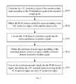
- FIG. 1 is a flowchart of a signal encoding method in the first embodiment of the present disclosure. The method includes the following steps:
- Step 101 Convert a first-domain signal into a second-domain signal.
- Step 102 Perform LP processing and LTP processing for the second-domain signal.
- Step 103 Obtain a long-term flag according to decision criteria.
- Step 104 Obtain a second-domain predictive signal according to the LP processing result and the LTP processing result when the long-term flag is the first flag; and obtain a second-domain predictive signal according to the LP processing result when the long-term flag is the second flag.
- Step 105 Convert the second-domain predictive signal into the first-domain predictive signal, and calculate the first-domain predictive residual signal.
- Step 106 Output a bit stream that includes the first-domain predictive residual signal.
- the long-term flag is obtained according to the decision criteria; the second-domain predictive signal is obtained according to the LP processing result and the LTP processing result when the long-term flag is the first flag, or the second-domain predictive signal is obtained according to the LP processing result when the long-term flag is the second flag, and the bit stream is obtained according to the second-domain predictive signal.
- the subsequent encoding process is performed adaptively according to the long-term flag. When the long-term flag is the second flag, it is not necessary to consider the LTP processing result, thus improving the compression performance of the codec.
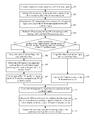
- FIG. 2 is a flowchart of a signal encoding method in the second embodiment of the present disclosure.
- the first domain is a nonlinear domain, and further, the first domain may be A-law or Mu-law; the second domain is a PCM domain; the LP processing is LPC processing, and the LTP processing is Long Term Prediction processing.
- Step 201 Convert a nonlinear-domain signal into a PCM-domain signal.
- x(i) represents the nonlinear-domain signal
- y(i) represents the PCM-domain signal
- Step 202 Perform LPC processing for the entire-frame signal y(i) of the PCM domain to obtain an LP processing result.
- the LP processing result includes the LPC predictive signal y′(i) which serves as an LP signal, and includes an LP coefficient, as expressed in the following formula:
- a j is an LP coefficient
- L is the frame length
- lpc_order is an LP order.
- Step 203 Calculate the LPC residual signal res(i) that serves as an LP residual signal according to the PCM-domain signal y(i) and the LPC predictive signal y′(i), where the LPC residual signal may be understood as an LP processing result.
- Step 204 Perform framing for the LPC residual signal res(i) and then perform LTP processing to obtain an LTP processing result.
- the framing operation is optional, and may be an adaptive framing operation.
- the LTP processing result includes a pitch and a pitch gain.
- the LTP processing in this step may include: performing pitch search for the LPC residual signal, obtaining the best pitch of the LPC residual signal, or obtaining both the best pitch and the pitch gain of the LPC residual signal.
- this step may include: if no framing is performed, performing pitch search for the PCM-domain signal of the current frame to obtain the best pitch of the PCM-domain signal, and then performing fine search for the LPC residual signal according to the best pitch of the PCM-domain signal to obtain the best pitch of the LPC residual signal or obtain both the best pitch and the pitch gain of the LPC residual signal; if framing is performed, before the framing operation, performing pitch search for the PCM-domain signal of the current frame to obtain the best pitch of the PCM-domain signal, using the best pitch of the PCM-domain signal of the current frame as the best pitch of the first subframe, and performing framing for the LPC residual signal according to the best pitch; performing fine search for the pitch of each subframe in the residual domain, namely, searching for the pitch of each subframe around the pitch of the previous subframe, thus facilitating differential coding for the subframe pitch, and obtaining the best pitch of each subframe, or obtaining both the best pitch and the pitch gain.
- the pitch gain may be selected adaptively according to the obtained best pitch.
- this embodiment specifies that the first M samples do not participate in the LTP processing, where M is a specified number.
- the pitch search is performed for the LPC residual signals res(i) of the samples other than the first M samples to obtain the pitch, pitch gain, and LTP residual signal z(i) of each subframe.
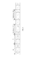
- FIG. 3 shows signals of a frame after framing in the signal encoding method in the second embodiment of the present disclosure.
- the first M samples do not participate in the framing or LTP processing, and the relation between M and lpc_order is: 0 ⁇ M ⁇ lpc_order.
- T 1 represents the pitch of the first subframe, and the samples from M to T 1 +M ⁇ 1 are the samples in the buffer.
- the total quantity of samples of the signals in a frame is L.
- g 1 represents the pitch gain of the first subframe.
- T j represents the pitch of subframe j
- g j represents the pitch gain of subframe j
- Step 205 Judge whether the product of the empirical factor and the energy of the LPC residual signals res(i) which have undergone no LTP processing is greater than the energy of the LTP residual signals z(i) which have undergone LTP processing; if so, proceed to step 206 ; otherwise, go to step 207 .
- E1 represents the energy of the LTP residual signal z(i); E represents the energy of the LPC residual signal res(i); and k may be 0 or M.
- an alternative of this step is: Judge whether the product of the empirical factor and the sum of absolute values of the LPC residual signals res(i) which have undergone no LTP processing is greater than the sum of absolute values of the LTP residual signals z(i) which have undergone LTP processing; if so, proceed to step 206 ; otherwise, go to step 207 .
- Step 206 Assign a value of the first flag to the long-term flag Tflag. Specifically, let Tflag be 1. Go to step 208 .
- the long-term flag may be the trigger signal of the LTP module. If Tflag is equal to 1, it indicates that the LTP module is enabled.
- Step 207 Assign a value of the second flag to the long-term flag Tflag. Specifically, let Tflag be 0. Go to step 210 . If Tflag is equal to 0, it indicates that the LTP module is disabled.
- Step 208 Obtain the LTP contribution signal res′(i) which serves as the LTP contribution signal according to the pitch, pitch gain and the LPC residual signal res(i).
- the function PCM2A[ ] refers to converting the PCM-domain signal into the A-law signal.
- Step 212 Calculate the difference between x(i) and x′(i) to obtain the nonlinear-domain predictive residual signal, and perform entropy coding for the nonlinear-domain predictive residual signal.
- Step 213 Output the bit stream that includes the entropy code of the nonlinear-domain predictive residual signal and the long-term flag. Specifically, when Tflag is equal to 0, the bit stream further includes an LPC coefficient a j ; when Tflag is equal to 1, the bit stream further includes an LPC coefficient a j , a pitch, and a pitch gain.
- the LTP module in the length-varying coding field, when Tflag is equal to 0, the LTP module is disabled, and no bit stream with the long-term flag needs to be output; when Tflag is equal to 1, the LTP module is enabled, and the bit stream that includes the first flag as the long-term flag is output, and this bit stream further includes an LPC coefficient a j , a pitch, and a pitch gain.
- the system knows whether the LTP module is enabled or disabled.
- the LTP processing almost makes no contribution, and the LTP module is disabled. Therefore, it is not necessary to consider the LTP contribution signals; fewer bits are consumed; and the compression performance of the encoder is improved.
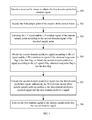
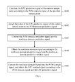
- FIG. 4 is a flowchart of a signal decoding method in the first embodiment of the present disclosure. The method includes the following steps:
- Step 301 Decode a received bit stream to obtain the first-domain predictive residual signal.
- Step 302 Decode the first sample point of the signals of the current frame.
- Step 303 Calculate the LP signal and the LP residual signal of the current sample point according to the second-domain signal of the decoded sample point.
- Step 304 Obtain the second-domain predictive signal according to the LP signal and the LTP contribution signal if the obtained long-term flag is the first flag, or obtain the second-domain predictive signal according to the LP signal if the obtained long-term flag is not the first flag, where the LTP contribution signal is obtained according to the LP residual signal of the decoded sample point.
- Step 305 Convert the second-domain predictive signal into the first-domain predictive signal, and decode the first-domain signal of the current sample point according to the first-domain predictive residual signal and the first-domain predictive signal.
- Step 306 Convert the first-domain signal of the current sample point into the second-domain signal.
- the subsequent decoding process is performed adaptively according to the long-term flag; when the long-term flag is the second flag, it is not necessary to consider the LTP contribution signals, thus simplifying the decoding process.
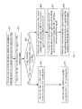
- FIG. 5 is a flowchart of a signal decoding method in the second embodiment of the present disclosure.
- the method in this embodiment may correspond to the signal coding method in the second embodiment, and the definitions of the terms and parameter expressions in this embodiment are the same as those in the second embodiment.
- the method in this embodiment includes the following steps:
- Step 401 Decode a received bit stream to obtain the nonlinear-domain predictive residual signal and the long-term flag.
- the bit stream may be decoded to obtain the long-term flag.
- the bit stream when the long-term flag Tflag is equal to 0, the bit stream further includes an LPC coefficient a j ; when Tflag is equal to 1, the bit stream further includes an LPC coefficient a j , a best pitch, and may further include a pitch gain. If the bit stream includes no pitch gain, the method in this embodiment further includes: selecting the pitch gain adaptively according to the best pitch.
- Step 402 Decode the first sample point of the signals of the current frame.
- the function A2PCM[ ] refers to converting the Alaw signal into the PCM-domain signal.
- the received bit stream is decoded to obtain the first-domain predictive residual signal, without obtaining the long-term flag which is the second flag.
- the decoding result includes the long-term flag which is the first flag, it indicates that the LTP module is enabled; otherwise, the LTP module is disabled.
- the system obtains the second-domain predictive signal according to the LP signal and the LTP contribution signal if the obtained long-term flag is the first flag, or obtains the second-domain predictive signal according to the LP signal if the obtained long-term flag is not the first flag, where the LTP contribution signal is obtained according to the LP residual signal of the decoded sample point.
- Step 403 Judge whether the value of the long-term flag is the first flag; if so, proceed to steps 404 - 405 ; otherwise, skip to steps 406 - 408 .
- the following decoding process is a cyclic recursive process.
- the following decoding steps are performed consecutively for every current sample point from the second sample point of the signals of the current frame:
- the system judges whether the first flag is obtained as the long-term flag; if so, steps 404 - 405 are performed; otherwise, steps 406 - 408 are performed.
- Step 404 Decode the first T 1 +M ⁇ 1 samples except the first sample point.
- step 404 in the signal decoding method in the second embodiment of the present disclosure. Further, step 404 may include the following steps:
- Step 4041 Calculate the LPC predictive signal y′(i) of the current sample point according to the PCM-domain signal y(i) of the decoded sample point through formula (15):
- the decoded sample point is the first sample point of the signals of the current frame.
- the decoding result in step 402 serves as a reference.
- Step 4044 Obtain the nonlinear-domain signal x(i) through formula (13) according to the nonlinear-domain predictive signal x′(i) and the nonlinear-domain predictive residual signal d(i).
- Step 405 Decode all the subframe signals except the first T 1 +M samples.
- FIG. 7 is a flowchart of step 405 in the signal decoding method in the second embodiment of the present disclosure.
- Step 405 may include the following steps:
- Step 4051 Calculate the LPC predictive signal y′′(i) of the current sample point according to the PCM-domain signal y(i) of the decoded sample point through formula (18):
- the decoded samples are the first T 1 +M samples.
- the decoding result in step 404 serves as a reference.
- Step 4054 Obtain the nonlinear-domain signal x(i) through formula (13) according to the nonlinear-domain contribution signal x′(i) and the nonlinear-domain predictive residual signal d(i).
- the LPC residual signal obtained in step 4055 is used to calculate the PCM-domain predictive signals of subsequent samples.
- Step 406 Calculate the LPC predictive signal y′(i) of the current sample point according to the PCM-domain signal y(i) of the decoded sample point through formula (22):
- Step 407 Use the LPC predictive signal y′(i) as the PCM-domain predictive signal, and convert the PCM-domain predictive signal into the nonlinear-domain predictive signal x′(i).
- y′′(i) y′(i)
- y′(i) may be converted into x′(i) directly.
- Step 408 Obtain the nonlinear-domain signal x(i) through formula (13) according to the nonlinear-domain predictive signal x′(i) and the nonlinear-domain predictive residual signal d(i).
- the subsequent decoding process is performed adaptively according to the long-term flag; when the long-term flag is the second flag, it is not necessary to consider the LTP contribution signals, thus simplifying the decoding process.
- FIG. 8 shows a structure of a signal coding apparatus in an embodiment of the present disclosure.
- the apparatus includes: a converting module 11 , an LP module 12 , an LTP module 13 , a deciding module 14 , a second-domain prediction module 15 , a first-domain predictive residual module 16 , and an outputting module 17 .
- the converting module 11 is adapted to: convert a first-domain signal into a second-domain signal, and convert a second-domain predictive signal into a first-domain predictive signal.
- the LP module 12 is adapted to perform LP processing for the second-domain signal.
- the LTP module 13 is adapted to perform LTP processing for the second-domain signal.
- the deciding module 14 is adapted to obtain a long-term flag according to decision criteria.
- the second-domain prediction module 15 is adapted to: obtain the second-domain predictive signal according to the LP processing result and the LTP processing result when the long-term flag is the first flag, and obtain the second-domain predictive signal according to the LP processing result when the long-term flag is the second flag.
- the first-domain predictive residual module 16 is adapted to calculate the first-domain predictive residual signal according to the first-domain predictive signal.
- the outputting module 17 is adapted to output a bit stream that includes the first-domain predictive residual signal.
- the foregoing LP processing result may include an LP coefficient, LP signals, and LP residual signals.
- the foregoing bit stream may further include an LP coefficient.
- the LTP module 13 may perform pitch search for the LP residual signals to obtain the best pitch or both the best pitch and the pitch gain of the LP residual signals, and obtain the LTP contribution signals.
- the LTP processing result may include the best pitch or both the best pitch and the pitch gain, LTP contribution signals, and LTP residual signals.
- the second-domain prediction module 15 is adapted to: use the sum of the LP residual signal and the LTP contribution signal as the second-domain predictive signal when the long-term flag is the first flag, or use the LP signal as the second-domain predictive signal when the long-term flag is the second flag.
- the deciding module 14 may make a decision according to two decision criteria, namely, judge whether the product of the empirical factor and the energy of the LP residual signal is greater than the energy of the LTP residual signal, or judge whether the product of the empirical factor and the sum of the absolute values of the LP residual signals is greater than the sum of the absolute values of the LTP residual signals. If so, the deciding module 14 assigns the value of the first flag to the long-term flag; otherwise, the deciding module 14 assigns the value of the second flag to the long-term flag.
- the apparatus in this embodiment may further include a pitch gain module which selects the pitch gain adaptively according to the obtained best pitch, and may further include a framing module which performs framing for the LP residual signals.
- the subsequent encoding process is performed adaptively according to the long-term flag; when the long-term flag is the second flag, it is not necessary to consider the LTP processing result, thus improving the compression performance of the codec.
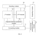
- FIG. 9 shows a structure of a signal decoding apparatus in an embodiment of the present disclosure.
- the apparatus includes: a bit stream decoding module 21 , a first sample point decoding module 22 , an LP module 23 , a second-domain prediction module 24 , a converting module 25 , a current sample point decoding module 26 , and an LP residual module 27 .
- the bit stream decoding module 21 is adapted to decode a received bit stream to obtain the first-domain predictive residual signal.
- the first sample point decoding module 22 is adapted to decode the first sample point of the signals of the current frame.
- the LP module 23 is adapted to calculate the LP signal of the current sample point according to the second-domain signal of the decoded sample point.
- the second-domain prediction module 24 is adapted to: obtain the second-domain predictive signal according to the LP signal and the LTP contribution signal if the obtained long-term flag is the first flag, or obtain the second-domain predictive signal according to the LP signal if the obtained long-term flag is not the first flag, where the LTP contribution signal is obtained according to the LP residual signal of the decoded sample point.
- the converting module 25 is adapted to: convert the second-domain predictive signal into the first-domain predictive signal, and convert the first-domain signal of the current sample point into the second-domain signal.
- the current sample point decoding module 26 is adapted to decode the first-domain signal of the current sample point according to the first-domain predictive residual signal and the first-domain predictive signal.
- the LP residual module 27 is adapted to obtain the LP residual signal according to the second-domain signal and the LP signal.
- the second-domain prediction module 24 uses the sum of the LP signal and the LTP contribution signal as the second-domain predictive signal; when the long-term flag is the first flag and the current sample point is not involved in the LTP processing at the encoder, the second-domain prediction module 24 uses the LP signal as the second-domain predictive signal.
- the apparatus in this embodiment may further include a pitch gain module which selects the pitch gain adaptively according to the obtained best pitch.
- the subsequent decoding process is performed adaptively according to the long-term flag; when the long-term flag is the second flag, it is not necessary to consider the LTP contribution signals, thus simplifying the decoding process.
- FIG. 10 shows a structure of a signal codec system in an embodiment of the present disclosure.
- the system includes a signal encoding apparatus 31 and a signal decoding apparatus 32 .
- the signal encoding apparatus 31 is adapted to: convert a first-domain signal into a second-domain signal; perform LP processing and LTP processing for the second-domain signal; obtain a long-term flag according to decision criteria; obtain the second-domain predictive signal according to the LP processing result and the LTP processing result when the long-term flag is the first flag; obtain the second-domain predictive signal according to the LP processing result when the long-term flag is the second flag; convert the second-domain predictive signal into the first-domain predictive signal, and calculate the first-domain predictive residual signal; and output a bit stream that includes the first-domain predictive residual signal.
- the signal decoding apparatus 32 is adapted to: decode the received bit stream to obtain the first-domain predictive residual signal; decode the first sample point of the signals of the current frame; perform the following decoding steps consecutively for every current sample point from the second sample point of the signals of the current frame: calculate the LP signal of the current sample point according to the second-domain signal of the decoded sample point; obtain the second-domain predictive signal according to the LP signal and the LTP contribution signal if the obtained long-term flag is the first flag, where the LTP contribution signal is obtained according to the LP residual signal of the decoded sample point; or obtain the second-domain predictive signal according to the LP signal if the obtained long-term flag is not the first flag; convert the second-domain predictive signal into the first-domain predictive signal, and decode the first-domain signal of the current sample point according to the first-domain predictive residual signal and the first-domain predictive signal; and convert the first-domain signal of the current sample point into the second-domain signal, and obtain the LP residual signal according to the second-domain signal and
- the signal encoding apparatus 31 in this embodiment may be any signal coding apparatus described in the foregoing embodiments; and the signal decoding apparatus 32 may be any signal decoding apparatus described in the foregoing embodiments.
- the program may be stored in a computer-readable storage medium. When being executed, the program performs steps of the foregoing method embodiments.
- the storage medium may be any medium suitable for storing program codes, for example, a Read Only Memory (ROM), a Random Access Memory (RAM), a magnetic disk, or a compact disk.
Landscapes
- Engineering & Computer Science (AREA)
- Signal Processing (AREA)
- Multimedia (AREA)
- Computational Linguistics (AREA)
- Health & Medical Sciences (AREA)
- Audiology, Speech & Language Pathology (AREA)
- Human Computer Interaction (AREA)
- Physics & Mathematics (AREA)
- Acoustics & Sound (AREA)
- Theoretical Computer Science (AREA)
- Compression, Expansion, Code Conversion, And Decoders (AREA)
- Compression Or Coding Systems Of Tv Signals (AREA)
Abstract
Description
res(i)=y(i)−y′(i),i=0,1, . . . ,L−1 (2)
z(i)=res(i),i=0,1, . . . ,T 1 +M−1. (3)
z(i)=res(i)−g 1 ·res(i−T 1),i=n 0 , . . . ,n 1−1. (4)
z j(i)=res j(i)−g j ·res j(i−T j),i=n j-1 , . . . ,n j−1. (5)
res′(i)=g·res(i−T) (8)
y″(i)=y′(i)+res′(i) (9)
y″(i)=y′(i) (10)
x′(i)=PCM2A[y″(i)] (11)
d(i)=x(i)−x′(i),i=0,1, . . . ,L−1 (12)
x(i)=d(i)+x′(i),i=0,1, . . . ,L−1 (13)
y(0)=A2PCM[x(0)],res(0)=y(0) (14)
x′(i)=PCM2A[y″(i)] (16)
res(i)=y(i)−y′(i),i=0,1, . . . ,T 1 +M−1 (17)
y″(i)=y′(i)+res′(i)=y′(i)+g·res(i−T) (19)
x′(i)=PCM2A[y″(i)] (20)
res(i)=y(i)−y′(i),i=n 0 , . . . ,L−1 (21)
Claims (22)
Priority Applications (1)
| Application Number | Priority Date | Filing Date | Title |
|---|---|---|---|
| US13/943,812 US8712763B2 (en) | 2008-12-31 | 2013-07-17 | Method for encoding signal, and method for decoding signal |
Applications Claiming Priority (7)
| Application Number | Priority Date | Filing Date | Title |
|---|---|---|---|
| CN200810247427.6 | 2008-12-31 | ||
| CN200810247427 | 2008-12-31 | ||
| CN200810247427 | 2008-12-31 | ||
| CN200910151835 | 2009-06-25 | ||
| CN2009101518356A CN101615395B (en) | 2008-12-31 | 2009-06-25 | Methods, devices and systems for encoding and decoding signals |
| CN200910151835.6 | 2009-06-25 | ||
| PCT/CN2009/076306 WO2010075792A1 (en) | 2008-12-31 | 2009-12-30 | Signal coding, decoding method and device, system thereof |
Related Parent Applications (1)
| Application Number | Title | Priority Date | Filing Date |
|---|---|---|---|
| PCT/CN2009/076306 Continuation WO2010075792A1 (en) | 2008-12-31 | 2009-12-30 | Signal coding, decoding method and device, system thereof |
Related Child Applications (1)
| Application Number | Title | Priority Date | Filing Date |
|---|---|---|---|
| US13/943,812 Continuation US8712763B2 (en) | 2008-12-31 | 2013-07-17 | Method for encoding signal, and method for decoding signal |
Publications (2)
| Publication Number | Publication Date |
|---|---|
| US20110313761A1 US20110313761A1 (en) | 2011-12-22 |
| US8515744B2 true US8515744B2 (en) | 2013-08-20 |
Family
ID=41495006
Family Applications (2)
| Application Number | Title | Priority Date | Filing Date |
|---|---|---|---|
| US13/172,575 Active US8515744B2 (en) | 2008-12-31 | 2011-06-29 | Method for encoding signal, and method for decoding signal |
| US13/943,812 Active US8712763B2 (en) | 2008-12-31 | 2013-07-17 | Method for encoding signal, and method for decoding signal |
Family Applications After (1)
| Application Number | Title | Priority Date | Filing Date |
|---|---|---|---|
| US13/943,812 Active US8712763B2 (en) | 2008-12-31 | 2013-07-17 | Method for encoding signal, and method for decoding signal |
Country Status (8)
| Country | Link |
|---|---|
| US (2) | US8515744B2 (en) |
| EP (2) | EP2680444A1 (en) |
| JP (2) | JP5436576B2 (en) |
| KR (1) | KR101350285B1 (en) |
| CN (1) | CN101615395B (en) |
| BR (1) | BRPI0923887A2 (en) |
| RU (1) | RU2486610C2 (en) |
| WO (1) | WO2010075792A1 (en) |
Cited By (1)
| Publication number | Priority date | Publication date | Assignee | Title |
|---|---|---|---|---|
| US20170047078A1 (en) * | 2014-04-29 | 2017-02-16 | Huawei Technologies Co.,Ltd. | Audio coding method and related apparatus |
Families Citing this family (10)
| Publication number | Priority date | Publication date | Assignee | Title |
|---|---|---|---|---|
| CN101615395B (en) * | 2008-12-31 | 2011-01-12 | 华为技术有限公司 | Methods, devices and systems for encoding and decoding signals |
| RU2510974C2 (en) | 2010-01-08 | 2014-04-10 | Ниппон Телеграф Энд Телефон Корпорейшн | Encoding method, decoding method, encoder, decoder, programme and recording medium |
| EP2551848A4 (en) * | 2010-03-23 | 2016-07-27 | Lg Electronics Inc | Method and apparatus for processing an audio signal |
| CN106409310B (en) | 2013-08-06 | 2019-11-19 | 华为技术有限公司 | A kind of audio signal classification method and device |
| CN112992164B (en) * | 2014-07-28 | 2024-12-06 | 日本电信电话株式会社 | Coding method, device, program product and recording medium |
| JP7150996B2 (en) | 2019-01-13 | 2022-10-11 | 華為技術有限公司 | High resolution audio encoding |
| AU2020214946B2 (en) | 2019-02-01 | 2023-06-08 | Beijing Bytedance Network Technology Co., Ltd. | Interactions between in-loop reshaping and inter coding tools |
| CN117499644A (en) | 2019-03-14 | 2024-02-02 | 北京字节跳动网络技术有限公司 | Signaling and syntax of loop shaping information |
| CN113632462B (en) | 2019-03-23 | 2023-08-22 | 北京字节跳动网络技术有限公司 | Default in-loop shaping parameters |
| CN113129913B (en) * | 2019-12-31 | 2024-05-03 | 华为技术有限公司 | Encoding and decoding method and encoding and decoding device for audio signal |
Citations (20)
| Publication number | Priority date | Publication date | Assignee | Title |
|---|---|---|---|---|
| JPH06130994A (en) | 1992-10-15 | 1994-05-13 | Hitachi Ltd | Speech coding method |
| WO1995016260A1 (en) | 1993-12-07 | 1995-06-15 | Pacific Communication Sciences, Inc. | Adaptive speech coder having code excited linear prediction with multiple codebook searches |
| US5652903A (en) * | 1994-11-01 | 1997-07-29 | Motorola, Inc. | DSP co-processor for use on an integrated circuit that performs multiple communication tasks |
| US5659698A (en) * | 1994-11-01 | 1997-08-19 | Motorola, Inc. | Method and apparatus for generating a circular buffer address in integrated circuit that performs multiple communications tasks |
| EP0848374A2 (en) | 1996-12-12 | 1998-06-17 | Nokia Mobile Phones Ltd. | A method and a device for speech encoding |
| US6094630A (en) | 1995-12-06 | 2000-07-25 | Nec Corporation | Sequential searching speech coding device |
| US6240386B1 (en) | 1998-08-24 | 2001-05-29 | Conexant Systems, Inc. | Speech codec employing noise classification for noise compensation |
| WO2002035522A1 (en) | 2000-10-26 | 2002-05-02 | Mitsubishi Denki Kabushiki Kaisha | Voice encoding method and apparatus |
| WO2002095734A2 (en) | 2001-05-18 | 2002-11-28 | Siemens Aktiengesellschaft | Method for controlling the amplification factor of a predictive voice encoder |
| CN1465044A (en) | 2001-06-15 | 2003-12-31 | 索尼公司 | Acoustic signal encoding method and apparatus, acoustic signal decoding method and apparatus, and recording medium |
| US20040167772A1 (en) * | 2003-02-26 | 2004-08-26 | Engin Erzin | Speech coding and decoding in a voice communication system |
| US20050075873A1 (en) * | 2003-10-02 | 2005-04-07 | Jari Makinen | Speech codecs |
| US20050102136A1 (en) * | 2003-11-11 | 2005-05-12 | Nokia Corporation | Speech codecs |
| WO2005081231A1 (en) | 2004-02-23 | 2005-09-01 | Nokia Corporation | Coding model selection |
| US20050251387A1 (en) | 2003-05-01 | 2005-11-10 | Nokia Corporation | Method and device for gain quantization in variable bit rate wideband speech coding |
| US20070143118A1 (en) | 2005-12-15 | 2007-06-21 | Hsin-Hao Chen | Apparatus and method for lossless audio signal compression/decompression through entropy coding |
| US20070239462A1 (en) * | 2000-10-23 | 2007-10-11 | Jari Makinen | Spectral parameter substitution for the frame error concealment in a speech decoder |
| WO2007128661A1 (en) | 2006-05-05 | 2007-11-15 | Thomson Licensing | Method and apparatus for lossless encoding of a source signal using a lossy encoded data stream and a lossless extension data stream |
| RU2319222C1 (en) | 2006-08-30 | 2008-03-10 | Валерий Юрьевич Тарасов | Method for encoding and decoding speech signal using linear prediction method |
| CN101197577A (en) | 2006-12-07 | 2008-06-11 | 展讯通信(上海)有限公司 | An encoding and decoding method for use in an audio processing framework |
Family Cites Families (8)
| Publication number | Priority date | Publication date | Assignee | Title |
|---|---|---|---|---|
| DE9006717U1 (en) * | 1990-06-15 | 1991-10-10 | Philips Patentverwaltung GmbH, 22335 Hamburg | Answering machine for digital recording and playback of voice signals |
| JPH07239699A (en) | 1994-02-28 | 1995-09-12 | Hitachi Ltd | Speech coding method and speech coding apparatus using this method |
| US5978756A (en) * | 1996-03-28 | 1999-11-02 | Intel Corporation | Encoding audio signals using precomputed silence |
| US7072832B1 (en) * | 1998-08-24 | 2006-07-04 | Mindspeed Technologies, Inc. | System for speech encoding having an adaptive encoding arrangement |
| US6947888B1 (en) | 2000-10-17 | 2005-09-20 | Qualcomm Incorporated | Method and apparatus for high performance low bit-rate coding of unvoiced speech |
| US7933767B2 (en) * | 2004-12-27 | 2011-04-26 | Nokia Corporation | Systems and methods for determining pitch lag for a current frame of information |
| CN101197576A (en) * | 2006-12-07 | 2008-06-11 | 上海杰得微电子有限公司 | Audio signal encoding and decoding method |
| CN101615395B (en) | 2008-12-31 | 2011-01-12 | 华为技术有限公司 | Methods, devices and systems for encoding and decoding signals |
-
2009
- 2009-06-25 CN CN2009101518356A patent/CN101615395B/en active Active
- 2009-12-30 EP EP20130186070 patent/EP2680444A1/en not_active Withdrawn
- 2009-12-30 JP JP2011543970A patent/JP5436576B2/en active Active
- 2009-12-30 RU RU2011132152/08A patent/RU2486610C2/en active
- 2009-12-30 KR KR1020117017706A patent/KR101350285B1/en active Active
- 2009-12-30 WO PCT/CN2009/076306 patent/WO2010075792A1/en not_active Ceased
- 2009-12-30 EP EP20090836079 patent/EP2385522A4/en not_active Withdrawn
- 2009-12-30 BR BRPI0923887-5A patent/BRPI0923887A2/en not_active IP Right Cessation
-
2011
- 2011-06-29 US US13/172,575 patent/US8515744B2/en active Active
-
2013
- 2013-07-17 US US13/943,812 patent/US8712763B2/en active Active
- 2013-08-09 JP JP2013165706A patent/JP5521097B2/en active Active
Patent Citations (26)
| Publication number | Priority date | Publication date | Assignee | Title |
|---|---|---|---|---|
| JPH06130994A (en) | 1992-10-15 | 1994-05-13 | Hitachi Ltd | Speech coding method |
| WO1995016260A1 (en) | 1993-12-07 | 1995-06-15 | Pacific Communication Sciences, Inc. | Adaptive speech coder having code excited linear prediction with multiple codebook searches |
| US5652903A (en) * | 1994-11-01 | 1997-07-29 | Motorola, Inc. | DSP co-processor for use on an integrated circuit that performs multiple communication tasks |
| US5659698A (en) * | 1994-11-01 | 1997-08-19 | Motorola, Inc. | Method and apparatus for generating a circular buffer address in integrated circuit that performs multiple communications tasks |
| US6094630A (en) | 1995-12-06 | 2000-07-25 | Nec Corporation | Sequential searching speech coding device |
| EP0848374A2 (en) | 1996-12-12 | 1998-06-17 | Nokia Mobile Phones Ltd. | A method and a device for speech encoding |
| US5933803A (en) | 1996-12-12 | 1999-08-03 | Nokia Mobile Phones Limited | Speech encoding at variable bit rate |
| US6240386B1 (en) | 1998-08-24 | 2001-05-29 | Conexant Systems, Inc. | Speech codec employing noise classification for noise compensation |
| US20070239462A1 (en) * | 2000-10-23 | 2007-10-11 | Jari Makinen | Spectral parameter substitution for the frame error concealment in a speech decoder |
| WO2002035522A1 (en) | 2000-10-26 | 2002-05-02 | Mitsubishi Denki Kabushiki Kaisha | Voice encoding method and apparatus |
| US20040148162A1 (en) | 2001-05-18 | 2004-07-29 | Tim Fingscheidt | Method for encoding and transmitting voice signals |
| WO2002095734A2 (en) | 2001-05-18 | 2002-11-28 | Siemens Aktiengesellschaft | Method for controlling the amplification factor of a predictive voice encoder |
| EP1388146A2 (en) | 2001-05-18 | 2004-02-11 | Siemens Aktiengesellschaft | Method for encoding and transmitting voice signals |
| CN1465044A (en) | 2001-06-15 | 2003-12-31 | 索尼公司 | Acoustic signal encoding method and apparatus, acoustic signal decoding method and apparatus, and recording medium |
| US20040167772A1 (en) * | 2003-02-26 | 2004-08-26 | Engin Erzin | Speech coding and decoding in a voice communication system |
| RU2316059C2 (en) | 2003-05-01 | 2008-01-27 | Нокиа Корпорейшн | Method and device for quantizing amplification in broadband speech encoding with alternating bitrate |
| US20050251387A1 (en) | 2003-05-01 | 2005-11-10 | Nokia Corporation | Method and device for gain quantization in variable bit rate wideband speech coding |
| US20050075873A1 (en) * | 2003-10-02 | 2005-04-07 | Jari Makinen | Speech codecs |
| US20050102136A1 (en) * | 2003-11-11 | 2005-05-12 | Nokia Corporation | Speech codecs |
| US20050192797A1 (en) | 2004-02-23 | 2005-09-01 | Nokia Corporation | Coding model selection |
| CN1922659A (en) | 2004-02-23 | 2007-02-28 | 诺基亚公司 | Coding model selection |
| WO2005081231A1 (en) | 2004-02-23 | 2005-09-01 | Nokia Corporation | Coding model selection |
| US20070143118A1 (en) | 2005-12-15 | 2007-06-21 | Hsin-Hao Chen | Apparatus and method for lossless audio signal compression/decompression through entropy coding |
| WO2007128661A1 (en) | 2006-05-05 | 2007-11-15 | Thomson Licensing | Method and apparatus for lossless encoding of a source signal using a lossy encoded data stream and a lossless extension data stream |
| RU2319222C1 (en) | 2006-08-30 | 2008-03-10 | Валерий Юрьевич Тарасов | Method for encoding and decoding speech signal using linear prediction method |
| CN101197577A (en) | 2006-12-07 | 2008-06-11 | 展讯通信(上海)有限公司 | An encoding and decoding method for use in an audio processing framework |
Non-Patent Citations (10)
| Title |
|---|
| 1st reexamination office action issued in corresponding Korea patent application 10-2011-7017706, dated May 3, 2013, and English translation thereof, total 6 pages. |
| European Communication pursuant to Article 94(3) dated Jun. 18, 2012, issued in related Application No. 09 836 079.5-1224. |
| Extended EU Search Report issued in related 09836079.5 dated Oct. 6, 2011. |
| International Search Report from the Chinese Patent Office in International Application No. PCT/CN2009/076306 mailed Apr. 15, 2010. |
| Itu-T, "Series G: Transmission Systems and Media, Digital Systems and Networks, Digital terminal equipments-Coding of voice and audio signals, Lossless compression of G.711 pulse code modulation", International Telecommunication Union, G.711.0, pp. i-iv and 1-64, (Sep. 2009). |
| Notice of allowance issued in corresponding Russian patent application 2011132152, dated Jan. 23, 2013,and English translation thereof, total 34 pages. |
| Office Action issued in related Russion Application No. 2011132152/20(047347) dated Sep. 22, 2011. |
| Rejection decision issued in corresponding Japanese patent application 2011-543970, dated Apr. 9, 2013, and English translation thereof, total 4 pages. |
| Rejection decision issued in corresponding Japanese patent application 2011-543970, dated Nov. 27, 2012,and English translation thereof, total 4 pages. |
| Written Opinion of the International Searching Authority in International Application No. PCT/CN2009/076306 dated Mar. 29, 2010. |
Cited By (3)
| Publication number | Priority date | Publication date | Assignee | Title |
|---|---|---|---|---|
| US20170047078A1 (en) * | 2014-04-29 | 2017-02-16 | Huawei Technologies Co.,Ltd. | Audio coding method and related apparatus |
| US10262671B2 (en) * | 2014-04-29 | 2019-04-16 | Huawei Technologies Co., Ltd. | Audio coding method and related apparatus |
| US10984811B2 (en) | 2014-04-29 | 2021-04-20 | Huawei Technologies Co., Ltd. | Audio coding method and related apparatus |
Also Published As
| Publication number | Publication date |
|---|---|
| EP2385522A1 (en) | 2011-11-09 |
| US20110313761A1 (en) | 2011-12-22 |
| KR101350285B1 (en) | 2014-01-10 |
| KR20110110262A (en) | 2011-10-06 |
| EP2680444A1 (en) | 2014-01-01 |
| RU2011132152A (en) | 2013-02-20 |
| RU2486610C2 (en) | 2013-06-27 |
| EP2385522A4 (en) | 2011-11-09 |
| JP5521097B2 (en) | 2014-06-11 |
| JP2012514225A (en) | 2012-06-21 |
| JP2013232013A (en) | 2013-11-14 |
| US20130304460A1 (en) | 2013-11-14 |
| JP5436576B2 (en) | 2014-03-05 |
| US8712763B2 (en) | 2014-04-29 |
| WO2010075792A1 (en) | 2010-07-08 |
| BRPI0923887A2 (en) | 2015-07-28 |
| CN101615395B (en) | 2011-01-12 |
| CN101615395A (en) | 2009-12-30 |
Similar Documents
| Publication | Publication Date | Title |
|---|---|---|
| US8515744B2 (en) | Method for encoding signal, and method for decoding signal | |
| USRE49363E1 (en) | Variable bit rate LPC filter quantizing and inverse quantizing device and method | |
| CN101305423B (en) | Adaptive time/frequency based audio encoding and decoding device and method | |
| EP1335353A2 (en) | Decoding apparatus, encoding apparatus, decoding method and encoding method | |
| CN102341844B (en) | Encoding method, decoding method, encoding device, decoding device | |
| US8380495B2 (en) | Transcoding method, transcoding device and communication apparatus used between discontinuous transmission | |
| JP2002268696A (en) | Acoustic signal encoding method, decoding method and apparatus, program and recording medium | |
| EP1005022A1 (en) | Speech encoding method and speech encoding system | |
| US7318024B2 (en) | Method of converting codes between speech coding and decoding systems, and device and program therefor | |
| US20060080090A1 (en) | Reusing codebooks in parameter quantization | |
| JP2613503B2 (en) | Speech excitation signal encoding / decoding method | |
| JPH1069298A (en) | Audio decoding method | |
| JPH04115300A (en) | Pitch predicting and encoding method for voice |
Legal Events
| Date | Code | Title | Description |
|---|---|---|---|
| AS | Assignment |
Owner name: HUAWEI TECHNOLOGIES CO., LTD., CHINA Free format text: ASSIGNMENT OF ASSIGNORS INTEREST;ASSIGNORS:ZHANG, DEJUN;MIAO, LEI;XU, JIANFENG;AND OTHERS;REEL/FRAME:026868/0448 Effective date: 20110702 |
|
| STCF | Information on status: patent grant |
Free format text: PATENTED CASE |
|
| FPAY | Fee payment |
Year of fee payment: 4 |
|
| MAFP | Maintenance fee payment |
Free format text: PAYMENT OF MAINTENANCE FEE, 8TH YEAR, LARGE ENTITY (ORIGINAL EVENT CODE: M1552); ENTITY STATUS OF PATENT OWNER: LARGE ENTITY Year of fee payment: 8 |
|
| MAFP | Maintenance fee payment |
Free format text: PAYMENT OF MAINTENANCE FEE, 12TH YEAR, LARGE ENTITY (ORIGINAL EVENT CODE: M1553); ENTITY STATUS OF PATENT OWNER: LARGE ENTITY Year of fee payment: 12 |