JP5436576B2 - Method for encoding a signal and method for decoding a signal - Google Patents
Method for encoding a signal and method for decoding a signal Download PDFInfo
- Publication number
- JP5436576B2 JP5436576B2 JP2011543970A JP2011543970A JP5436576B2 JP 5436576 B2 JP5436576 B2 JP 5436576B2 JP 2011543970 A JP2011543970 A JP 2011543970A JP 2011543970 A JP2011543970 A JP 2011543970A JP 5436576 B2 JP5436576 B2 JP 5436576B2
- Authority
- JP
- Japan
- Prior art keywords
- signal
- region
- flag
- prediction
- ltp
- Prior art date
- Legal status (The legal status is an assumption and is not a legal conclusion. Google has not performed a legal analysis and makes no representation as to the accuracy of the status listed.)
- Active
Links
- 238000000034 method Methods 0.000 title claims description 93
- 230000007774 longterm Effects 0.000 claims description 84
- 238000006243 chemical reaction Methods 0.000 claims description 8
- 238000009432 framing Methods 0.000 description 9
- 230000006835 compression Effects 0.000 description 8
- 238000007906 compression Methods 0.000 description 8
- 230000003044 adaptive effect Effects 0.000 description 7
- 230000005236 sound signal Effects 0.000 description 4
- 230000014509 gene expression Effects 0.000 description 3
- 238000013139 quantization Methods 0.000 description 3
- 230000005284 excitation Effects 0.000 description 2
- 238000012986 modification Methods 0.000 description 2
- 230000004048 modification Effects 0.000 description 2
- 230000000737 periodic effect Effects 0.000 description 1
- 230000003595 spectral effect Effects 0.000 description 1
- 238000001228 spectrum Methods 0.000 description 1
Images


Classifications
-
- G—PHYSICS
- G10—MUSICAL INSTRUMENTS; ACOUSTICS
- G10L—SPEECH ANALYSIS OR SYNTHESIS; SPEECH RECOGNITION; SPEECH OR VOICE PROCESSING; SPEECH OR AUDIO CODING OR DECODING
- G10L19/00—Speech or audio signals analysis-synthesis techniques for redundancy reduction, e.g. in vocoders; Coding or decoding of speech or audio signals, using source filter models or psychoacoustic analysis
- G10L19/04—Speech or audio signals analysis-synthesis techniques for redundancy reduction, e.g. in vocoders; Coding or decoding of speech or audio signals, using source filter models or psychoacoustic analysis using predictive techniques
- G10L19/08—Determination or coding of the excitation function; Determination or coding of the long-term prediction parameters
- G10L19/09—Long term prediction, i.e. removing periodical redundancies, e.g. by using adaptive codebook or pitch predictor
-
- G—PHYSICS
- G10—MUSICAL INSTRUMENTS; ACOUSTICS
- G10L—SPEECH ANALYSIS OR SYNTHESIS; SPEECH RECOGNITION; SPEECH OR VOICE PROCESSING; SPEECH OR AUDIO CODING OR DECODING
- G10L19/00—Speech or audio signals analysis-synthesis techniques for redundancy reduction, e.g. in vocoders; Coding or decoding of speech or audio signals, using source filter models or psychoacoustic analysis
- G10L19/04—Speech or audio signals analysis-synthesis techniques for redundancy reduction, e.g. in vocoders; Coding or decoding of speech or audio signals, using source filter models or psychoacoustic analysis using predictive techniques
- G10L19/08—Determination or coding of the excitation function; Determination or coding of the long-term prediction parameters
-
- H—ELECTRICITY
- H03—ELECTRONIC CIRCUITRY
- H03M—CODING; DECODING; CODE CONVERSION IN GENERAL
- H03M7/00—Conversion of a code where information is represented by a given sequence or number of digits to a code where the same, similar or subset of information is represented by a different sequence or number of digits
- H03M7/30—Compression; Expansion; Suppression of unnecessary data, e.g. redundancy reduction
-
- H—ELECTRICITY
- H04—ELECTRIC COMMUNICATION TECHNIQUE
- H04N—PICTORIAL COMMUNICATION, e.g. TELEVISION
- H04N19/00—Methods or arrangements for coding, decoding, compressing or decompressing digital video signals
- H04N19/50—Methods or arrangements for coding, decoding, compressing or decompressing digital video signals using predictive coding
-
- G—PHYSICS
- G10—MUSICAL INSTRUMENTS; ACOUSTICS
- G10L—SPEECH ANALYSIS OR SYNTHESIS; SPEECH RECOGNITION; SPEECH OR VOICE PROCESSING; SPEECH OR AUDIO CODING OR DECODING
- G10L19/00—Speech or audio signals analysis-synthesis techniques for redundancy reduction, e.g. in vocoders; Coding or decoding of speech or audio signals, using source filter models or psychoacoustic analysis
- G10L19/0017—Lossless audio signal coding; Perfect reconstruction of coded audio signal by transmission of coding error
Description
本出願は、参照により本明細書に組み込まれる、2008年12月31日に出願された「Method for Encoding Signal,and Method for Decoding Signal」という名称の中国特許出願第200810247427.6号、および2009年6月25日に出願された「Method for Encoding Signal,and Method for Decoding Signal」という名称の中国特許出願第200910151835.6号の優先権を主張するものである。 This application is Chinese Patent Application No. 200810224727.6, entitled “Method for Encoding Signal, and Method for Decoding Signal,” filed Dec. 31, 2008, and incorporated herein by reference. It claims the priority of Chinese Patent Application No. 2009101531835.6 filed June 25, entitled “Method for Encoding Signal, and Method for Decoding Signal”.
本開示は音声の符号化および復号に関し、詳細には、信号を符号化し、復号する方法、装置、およびシステムに関する。 The present disclosure relates to audio encoding and decoding, and in particular, to a method, apparatus, and system for encoding and decoding signals.
音声符号化分野において広く適用される符号化モデルのうちの1つが符号励振線形予測(CELP:Code Excited Linear Prediction)である。CELPモデルはほぼ白色の励振信号を使用して2つの時間変化線形再帰型フィルタを励振する。励振信号は一般にガウス白色雑音シーケンスから成るコードブックの中から選択される。各フィルタのフィードバックループは予測器を含む。予測器の1つが長期予測器(またはピッチ予測器)であり、これはP(z)で表される。P(z)は発声された音声の音調構造(例えばスペクトルの微細な構造など)を生成するのに使用される。別の一般的な予測器が短期予測器であり、F(z)で表される。F(z)は音声の短期スペクトルエンベロープを回復するのに使用される。このモデルはその逆のプロセスに由来する。すなわち、F(z)は音声信号の近いサンプル点の冗長性を除去するのに使用され、P(z)は音声信号の遠いサンプル点の冗長性を除去するのに使用される。2つのレベルの予測により正規化された残差信号が獲得される。残差信号はおおよそ標準正規分布を示す。 One of the coding models widely applied in the speech coding field is Code Excited Linear Prediction (CELP). The CELP model excites two time-varying linear recursive filters using a substantially white excitation signal. The excitation signal is typically selected from a codebook consisting of a Gaussian white noise sequence. Each filter's feedback loop includes a predictor. One of the predictors is a long-term predictor (or pitch predictor), which is represented by P (z). P (z) is used to generate the tone structure (eg, fine structure of the spectrum) of the spoken speech. Another common predictor is a short-term predictor, denoted F (z). F (z) is used to recover the short-term spectral envelope of the speech. This model comes from the reverse process. That is, F (z) is used to remove the redundancy of near sample points of the speech signal, and P (z) is used to remove the redundancy of far sample points of the speech signal. A normalized residual signal is obtained by two levels of prediction. The residual signal shows a standard normal distribution.
CELPモデルが損失の多い圧縮分野に適用されるときには、音声信号x(i)をまず線形予測符号化(LPC:Linear Predictive Coding)解析して残差信号res(i)が獲得される。LPC残差信号res(i)がフレーム化された後で、各サブフレーム信号に長期予測(LTP:Long−Term Prediction)解析を施して、対応する適応コードブックおよび適応コードブック利得が獲得される。適応コードブックは、自己相関など、多くの方法において探索され得る。LPC残差信号res(i)の長期依存性が除去された後で、LTP残差信号x2(i)が獲得される。代数コードブックを使用してLTP残差信号x2(i)が特徴付けられ、または当てはめられた後で、全符号化プロセスが完了する。最後に、適応コードブックおよび固定コードブックが符号化されてビットストリームに書き込まれ、適応コードブック利得および固定コードブック利得についての結合ベクトル量子化(joint vector quantization)またはスカラ量子化が行われる。コードブックにおいて、適応コードブック利得または固定コードブック利得が最適な利得として選択される。最適な利得に対応するインデックスが復号器に送られる。全符号化プロセスは、パルス符号変調(PCM:Pulse Code Modulation)領域で行われる。 When the CELP model is applied to a lossy compression field, the speech signal x (i) is first subjected to linear predictive coding (LPC) analysis to obtain a residual signal res (i). After the LPC residual signal res (i) is framed, each subframe signal is subjected to long-term prediction (LTP) analysis to obtain a corresponding adaptive codebook and adaptive codebook gain. . The adaptive codebook can be searched in many ways, such as autocorrelation. After the long-term dependence of the LPC residual signal res (i) is removed, the LTP residual signal x2 (i) is obtained. After the LTP residual signal x2 (i) is characterized or fitted using an algebraic codebook, the entire encoding process is complete. Finally, the adaptive codebook and fixed codebook are encoded and written to the bitstream, and joint vector quantization or scalar quantization is performed on the adaptive codebook gain and fixed codebook gain. In the codebook, an adaptive codebook gain or a fixed codebook gain is selected as the optimum gain. An index corresponding to the optimal gain is sent to the decoder. The entire encoding process is performed in a pulse code modulation (PCM) domain.
無損失圧縮の分野では、MPEG ALS(Moving Pictures Experts Group Audio Lossless Coding)装置は、予測のために音声信号の短期および長期の依存性も使用する。その予測プロセスは以下の通りである。まず、音声信号についてLPCが行われ、LPC係数にエントロピー符号化が施され、ビットストリームに書き込まれる。LTPのピッチおよびピッチ利得を獲得するためにLPC残差信号についてLTPが行われ、LPC残差信号がビットストリームに書き込まれる。LTPの後でLTP残差信号が獲得される。次いで、LTP残差信号にエントロピー符号化が施されてビットストリームに書き込まれ、全符号化プロセスが終了する。 In the field of lossless compression, Moving Pictures Experts Audio Loss Coding (MPEG ALS) devices also use the short and long term dependencies of audio signals for prediction. The prediction process is as follows. First, LPC is performed on the audio signal, entropy coding is performed on the LPC coefficients, and the LPC coefficients are written into the bit stream. LTP is performed on the LPC residual signal to obtain the LTP pitch and pitch gain, and the LPC residual signal is written to the bitstream. An LTP residual signal is acquired after LTP. The LTP residual signal is then entropy encoded and written to the bitstream, ending the entire encoding process.
前述の先行技術においては、音声信号の周期性が少ない場合、LTP処理の貢献度はほとんどない。この場合、LTP残差信号はそれでもなおビットストリームに書き込まれる。結果としてピッチ利得量子化は過度に多くのビットを消費し、符号器の圧縮性能が低下する。 In the above-described prior art, when the periodicity of the audio signal is small, there is almost no contribution of the LTP processing. In this case, the LTP residual signal is still written to the bitstream. As a result, pitch gain quantization consumes too many bits and degrades the compression performance of the encoder.
本開示の実施形態はコーデックの圧縮性能を改善するように信号を符号化し、復号する方法、装置、およびシステムを提供する。 Embodiments of the present disclosure provide a method, apparatus, and system for encoding and decoding a signal to improve the compression performance of a codec.
信号符号化方法は、
第1領域の信号を第2領域の信号に変換すること、
第2領域の信号についてLP(Linear Predictive)処理およびLTP処理を行うこと、
判断基準に従って長期フラグを獲得すること、
長期フラグが第1のフラグであるときにLP処理の結果およびLTP処理の結果に従って第2領域の予測信号を獲得し、長期フラグが第2のフラグであるときにLP処理の結果に従って第2領域の予測信号を獲得すること、
第2領域の予測信号を第1領域の予測信号に変換して第1領域の予測残差信号を計算すること、ならびに
第1領域の予測残差信号を含むビットストリームを出力すること
を含む。
The signal encoding method is
Converting the signal of the first region into the signal of the second region;
Performing LP (Linear Predictive) processing and LTP processing on the signals in the second region;
Obtaining a long-term flag according to criteria,
When the long-term flag is the first flag, the second region prediction signal is acquired according to the LP processing result and the LTP processing result, and when the long-term flag is the second flag, the second region is determined according to the LP processing result. Obtaining a predicted signal of
Converting a prediction signal of the second region into a prediction signal of the first region to calculate a prediction residual signal of the first region, and outputting a bitstream including the prediction residual signal of the first region.
信号復号方法は、
受け取ったビットストリームを復号して復号された第1領域の予測残差信号を獲得すること、
現在フレーム信号の第1のサンプル点を復号すること、
現在フレーム信号の第2のサンプル点の各現在サンプル点について連続して、
復号されたサンプル点の第2領域の信号に従って現在サンプル点のLP信号を計算するステップと、
獲得された長期フラグが第1のフラグである場合に、LP信号と、復号されたサンプル点のLP残差信号に従って獲得されるLTP寄与信号とに従って第2領域の予測信号を獲得するステップと、
獲得される長期フラグが第1のフラグでない場合に、LP信号に従って第2領域の予測信号を獲得するステップと、
第2領域の予測信号を第1領域の予測信号に変換し、第1領域の予測残差信号および第1領域の予測信号に従って現在サンプル点の第1領域の信号を復号するステップと、
現在サンプル点の第1領域の信号を第2領域の信号に変換し、第2領域の信号およびLP信号に従ってLP残差信号を獲得するステップと
の各復号ステップを実行すること
を含む。
The signal decoding method is
Decoding the received bitstream to obtain a decoded first region prediction residual signal;
Decoding the first sample point of the current frame signal;
Successively for each current sample point of the second sample point of the current frame signal,
Calculating the LP signal of the current sample point according to the decoded signal of the second region of sample points;
Obtaining a prediction signal of the second region according to the LP signal and the LTP contribution signal obtained according to the LP residual signal of the decoded sample points when the obtained long-term flag is the first flag;
Obtaining a prediction signal of the second region according to the LP signal when the acquired long-term flag is not the first flag;
Converting the prediction signal of the second region into the prediction signal of the first region, and decoding the signal of the first region of the current sample point according to the prediction residual signal of the first region and the prediction signal of the first region;
Converting the first region signal of the current sample point into a second region signal and obtaining an LP residual signal in accordance with the second region signal and the LP signal.
信号符号化装置は、
第1領域の信号を第2領域の信号に変換し、第2領域の予測信号を第1領域の予測信号に変換するように適合された変換モジュールと、
第2領域の信号についてLP処理を行うように適合されたLPモジュールと、
第2領域の信号についてLTP処理を行うように適合されたLTPモジュールと、
判断基準に従って長期フラグを獲得するように適合された判断モジュールと、
長期フラグが第1のフラグであるときにLP処理の結果およびLTP処理の結果に従って第2領域の予測信号を獲得し、長期フラグが第2のフラグであるときにLP処理の結果に従って第2領域の予測信号を獲得するように適合された第2領域の予測モジュールと、
第1領域の予測信号に従って第1領域の予測残差信号を計算するように適合された第1領域の予測残差モジュールと、
第1領域の予測残差信号を含むビットストリームを出力するように適合された出力モジュールと
を含む。
The signal encoding device
A conversion module adapted to convert a first region signal into a second region signal and convert a second region prediction signal into a first region prediction signal;
An LP module adapted to perform LP processing on signals in the second region;
An LTP module adapted to perform LTP processing on signals in the second region;
A decision module adapted to acquire a long-term flag according to a decision criterion;
When the long-term flag is the first flag, the second region prediction signal is acquired according to the LP processing result and the LTP processing result, and when the long-term flag is the second flag, the second region is determined according to the LP processing result. A second domain prediction module adapted to obtain a prediction signal of
A first region prediction residual module adapted to calculate a first region prediction residual signal according to the first region prediction signal;
An output module adapted to output a bitstream including a first region prediction residual signal.
信号復号装置は、
受け取ったビットストリームを復号して第1領域の予測残差信号を獲得するように適合されたビットストリーム復号モジュールと、
現在フレームの信号の第1のサンプル点を復号するように適合された第1のサンプル点復号モジュールと、
復号されたサンプル点の第2領域の信号に従って現在サンプル点のLP信号を計算するように適合されたLPモジュールと、
獲得された長期フラグが第1のフラグである場合に、LP信号と、復号されたサンプル点のLP残差信号に従って獲得されるLTP寄与信号とに従って第2領域の予測信号を獲得し、獲得された長期フラグが第1のフラグでない場合に、LP信号に従って第2領域の予測信号を獲得するように適合された第2領域の予測モジュールと、
第2領域の予測信号を第1領域の予測信号に変換し、現在サンプル点の第1領域の信号を第2領域の信号に変換するように適合された変換モジュールと、
第1領域の予測残差信号および第1領域の予測信号に従って現在サンプル点の第1領域の信号を復号するように適合された現在サンプル点復号モジュールと、
第2領域の信号およびLP予測信号に従ってLP残差信号を獲得するように適合されたLP残差モジュールと
を含む。
The signal decoding device
A bitstream decoding module adapted to decode the received bitstream to obtain a first region prediction residual signal;
A first sample point decoding module adapted to decode a first sample point of the signal of the current frame;
An LP module adapted to calculate the LP signal of the current sample point according to the signal of the second region of decoded sample points;
If the acquired long-term flag is the first flag, the second region prediction signal is acquired according to the LP signal and the LTP contribution signal acquired according to the LP residual signal of the decoded sample point, A second region prediction module adapted to obtain a second region prediction signal according to the LP signal when the long-term flag is not the first flag;
A conversion module adapted to convert the prediction signal of the second region into a prediction signal of the first region and convert the signal of the first region at the current sample point into a signal of the second region;
A current sample point decoding module adapted to decode the first region signal of the current sample point according to the first region prediction residual signal and the first region prediction signal;
An LP residual module adapted to obtain an LP residual signal in accordance with the second region signal and the LP prediction signal.
信号コーデックシステムは、
第1領域の信号を第2領域の信号に変換し、第2領域の信号についてLP処理およびLTP処理を行い、判断基準に従って長期フラグを獲得し、長期フラグが第1のフラグであるときにLP処理の結果およびLTP処理の結果に従って第2領域の予測信号を獲得し、長期フラグが第2のフラグであるときにLP処理の結果に従って第2領域の予測信号を獲得し、第2領域の予測信号を第1領域の予測信号に変換して第1領域の予測残差信号を計算し、第1領域の予測残差信号を含むビットストリームを出力するように適合された信号符号化装置と、
受け取ったビットストリームを復号して第1領域の予測残差信号および長期フラグを獲得し、現在フレームの信号の第1のサンプル点を復号し、現在フレームの信号の第2のサンプル点の各現在サンプル点について連続して、復号されたサンプル点の第2領域の信号に従って現在サンプル点のLP信号を計算するステップと、獲得された長期フラグが第1のフラグである場合に、LP信号と、復号されたサンプル点のLP残差信号に従って獲得されるLTP寄与信号とに従って第2領域の予測信号を獲得し、獲得された長期フラグが第1のフラグでない場合に、LP信号に従って第2領域の予測信号を獲得するステップと、第2領域の予測信号を第1領域の予測信号に変換し、第1領域の予測残差信号および第1領域の予測信号に従って現在サンプル点の第1領域の信号を復号するステップと、現在サンプル点の第1領域の信号を第2領域の信号に変換し、第2領域の信号およびLP信号に従ってLP残差信号を獲得するステップとの各復号ステップを実行するように適合された信号復号装置と
を含む。
Signal codec system
The first region signal is converted into the second region signal, LP processing and LTP processing are performed on the second region signal, a long-term flag is obtained according to the criterion, and LP when the long-term flag is the first flag The second region prediction signal is obtained according to the processing result and the LTP processing result, and when the long-term flag is the second flag, the second region prediction signal is obtained according to the LP processing result, and the second region prediction signal is obtained. A signal encoding device adapted to convert the signal into a prediction signal of the first region, calculate a prediction residual signal of the first region, and output a bitstream including the prediction residual signal of the first region;
The received bitstream is decoded to obtain a prediction residual signal and a long-term flag for the first region, a first sample point of the current frame signal is decoded, and each current second sample point of the current frame signal Continuously calculating the LP signal of the current sample point according to the signal of the second region of the decoded sample points continuously for the sample point, and the LP signal if the acquired long-term flag is the first flag; A prediction signal of the second region is obtained according to the LTP contribution signal obtained according to the LP residual signal of the decoded sample point, and when the acquired long-term flag is not the first flag, the second region prediction signal is obtained according to the LP signal. Obtaining a prediction signal, converting the prediction signal of the second region into a prediction signal of the first region, and presenting according to the prediction residual signal of the first region and the prediction signal of the first region A first region signal of a sample point, a step of converting a first region signal of a current sample point into a second region signal, and obtaining an LP residual signal according to the second region signal and the LP signal And a signal decoding device adapted to perform each decoding step.
本開示の実施形態では、後続の符号化または復号プロセスが長期フラグに従って適応的に行われる。長期フラグが第2のフラグであるときにはLTP処理の結果を考慮する必要がなく、よってコーデックの圧縮性能が向上する。 In the embodiments of the present disclosure, the subsequent encoding or decoding process is performed adaptively according to the long-term flag. When the long-term flag is the second flag, it is not necessary to consider the result of the LTP process, and therefore the compression performance of the codec is improved.
以下、添付の図面および例示的実施形態を参照して本開示をより詳細に説明する。 The present disclosure will now be described in more detail with reference to the accompanying drawings and exemplary embodiments.
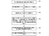
図1は本開示の第1の実施形態における信号符号化方法の流れ図である。この方法は以下のステップを含む。 FIG. 1 is a flowchart of a signal encoding method according to the first embodiment of the present disclosure. The method includes the following steps.
ステップ101:第1領域の信号を第2領域の信号に変換する。 Step 101: Convert the signal of the first region into the signal of the second region.
ステップ102:第2領域の信号についてLP処理およびLTP処理を行う。 Step 102: LP processing and LTP processing are performed on the signals in the second region.
ステップ103:判断基準に従って長期フラグを獲得する。 Step 103: Acquire a long-term flag according to the judgment criteria.
ステップ104:長期フラグが第1のフラグであるときにはLP処理の結果およびLTP処理の結果に従って第2領域の予測信号を獲得し、長期フラグが第2のフラグであるときにはLP処理の結果に従って第2領域の予測信号を獲得する。 Step 104: When the long-term flag is the first flag, the second region prediction signal is acquired according to the LP processing result and the LTP processing result, and when the long-term flag is the second flag, the second signal is obtained according to the LP processing result. Get the prediction signal for the region.
ステップ105:第2領域の予測信号を第1領域の予測信号に変換し、第1領域の予測残差信号を計算する。 Step 105: Convert the prediction signal of the second region into the prediction signal of the first region, and calculate the prediction residual signal of the first region.
ステップ106:第1領域の予測残差信号を含むビットストリームを出力する。 Step 106: Output a bitstream including the prediction residual signal of the first region.
この実施形態では、長期フラグが判断基準に従って獲得され、長期フラグが第1のフラグであるときには第2領域の予測信号がLP処理の結果およびLTP処理の結果に従って獲得され、長期フラグが第2のフラグであるときには第2領域の予測信号がLP処理の結果に従って獲得され、ビットストリームが第2領域の予測信号に従って獲得される。この実施形態では、後続の符号化プロセスは長期フラグに従って適応的に行われる。長期フラグが第2のフラグであるときには、LTP処理の結果を考慮する必要がなく、よってコーデックの圧縮性能が向上する。 In this embodiment, the long-term flag is obtained according to the criterion, and when the long-term flag is the first flag, the prediction signal of the second region is obtained according to the result of the LP process and the result of the LTP process, and the long-term flag is the second flag. When it is a flag, the prediction signal of the second region is acquired according to the result of the LP process, and the bit stream is acquired according to the prediction signal of the second region. In this embodiment, the subsequent encoding process is performed adaptively according to the long-term flag. When the long-term flag is the second flag, it is not necessary to consider the result of the LTP process, and thus the compression performance of the codec is improved.
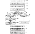
図2は本開示の第2の実施形態における信号符号化方法の流れ図である。この実施形態では、第1領域は非線形領域であり、さらに第1領域はA−則またはμ−則とすることができ、第2領域はPCM領域であり、LP処理はLPC処理であり、LTP処理は長期予測処理である。 FIG. 2 is a flowchart of a signal encoding method according to the second embodiment of the present disclosure. In this embodiment, the first region is a non-linear region, the first region can be an A-law or μ-law, the second region is a PCM region, the LP process is an LPC process, and the LTP The process is a long-term prediction process.
この実施形態の方法は以下のステップを含む。 The method of this embodiment includes the following steps.
ステップ201:非線形領域信号をPCM領域信号に変換する。 Step 201: Convert a nonlinear domain signal into a PCM domain signal.
x(i)は非線形領域信号を表し、y(i)はPCM領域信号を表す。変換プロセスが精度損失を伴うと仮定すると、対応する後方変換プロセスは精度損失を伴わない。 x (i) represents a nonlinear domain signal and y (i) represents a PCM domain signal. Assuming that the conversion process involves a loss of accuracy, the corresponding backward conversion process does not involve a loss of accuracy.
ステップ202:PCM領域の全フレーム信号y(i)についてLPC処理を行ってLP処理の結果を獲得する。LP処理の結果は、次式で表すように、LP信号として働き、LP係数を含むLPC信号y’(i)を含む。 Step 202: LPC processing is performed on all frame signals y (i) in the PCM area to obtain a result of LP processing. The result of the LP process includes an LPC signal y ′ (i) that acts as an LP signal and includes LP coefficients, as represented by the following equation.

式中、ajはLP係数であり、Lはフレーム長であり、lpc_orderはLP次数である。y’(0)=0であると仮定すると、i<0のとき、y(i)=0である。 In the equation, a j is an LP coefficient, L is a frame length, and lpc_order is an LP order. Assuming that y ′ (0) = 0, when i <0, y (i) = 0.
ステップ203:PCM領域信号y(i)およびLPC信号y’(i)に従ってLP残差信号として機能するLPC残差信号res(i)を計算する。その場合LPC残差信号はLP処理の結果として理解され得る。
res(i)=y(i)−y’(i)、i=0,1,…,L−1 (2)
Step 203: Calculate an LPC residual signal res (i) that functions as an LP residual signal according to the PCM domain signal y (i) and the LPC signal y ′ (i). In that case, the LPC residual signal can be understood as a result of LP processing.
res (i) = y (i) −y ′ (i), i = 0, 1,..., L−1 (2)
ステップ204:LTP残差信号res(i)についてフレーム化を行い、次いでLTP処理を行ってLTP処理の結果を獲得する。フレーム化操作は任意選択であり、適応的フレーム化操作とすることができる。LTP処理の結果はピッチおよびピッチ利得を含む。 Step 204: Frame the LTP residual signal res (i), and then perform the LTP process to obtain the result of the LTP process. The framing operation is optional and can be an adaptive framing operation. The result of LTP processing includes pitch and pitch gain.
具体的には、このステップのLTP処理は、LPC残差信号のピッチ探索を行うこと、LPC残差信号の最適のピッチを獲得すること、またはLPC残差信号の最適のピッチとピッチ利得の両方を獲得することを含み得る。 Specifically, the LTP processing of this step includes performing a pitch search of the LPC residual signal, obtaining an optimal pitch of the LPC residual signal, or both an optimal pitch and pitch gain of the LPC residual signal. Earning.
具体的には、このステップは、フレーム化が行われない場合には、現在フレームのPCM領域信号のピッチ探索を行ってPCM領域信号の最適のピッチを獲得し、次いで、PCM領域信号の最適のピッチに従ってLPC残差信号の密探索を行ってLPC残差信号の最適のピッチを獲得し、またはLPC残差信号の最適のピッチとピッチ利得の両方を獲得すること、フレーム化が行われる場合には、フレーム化操作の前に、現在フレームのPCM領域信号のピッチ探索を行ってPCM領域信号の最適のピッチを獲得し、現在フレームのPCM領域信号の最適のピッチを第1のサブフレームの最適のピッチとして使用し、最適のピッチに従ってLPC残差信号についてのフレーム化を行うこと、残差領域内の各サブフレームのピッチの密探索を行い、すなわち、前のサブフレームのピッチの前後の各サブフレームのピッチを探索し、よって、サブフレームピッチについての差分符号化を円滑化し、各サブフレームの最適のピッチを獲得し、または最適のピッチとピッチ利得の両方を獲得すること、を含み得る。 Specifically, this step performs a pitch search of the PCM region signal of the current frame to obtain the optimal pitch of the PCM region signal if no framing is performed, and then optimizes the PCM region signal. Perform a fine search of the LPC residual signal according to the pitch to obtain the optimum pitch of the LPC residual signal, or obtain both the optimum pitch and pitch gain of the LPC residual signal, when framing is performed Performs the pitch search of the PCM region signal of the current frame to obtain the optimal pitch of the PCM region signal before the framing operation, and obtains the optimal pitch of the PCM region signal of the current frame to the optimum of the first subframe The LPC residual signal is framed according to the optimum pitch, and a fine search of the pitch of each subframe in the residual area is performed. I.e., search for the pitch of each subframe before and after the pitch of the previous subframe, thus facilitating differential encoding for the subframe pitch and obtaining the optimal pitch of each subframe, or the optimal pitch And obtaining both pitch gain.
前述のピッチを探索するプロセスでは、ピッチ利得が獲得されない場合、ピッチ利得は獲得された最適のピッチに従って適応的に選択され得る。 In the process of searching for a pitch as described above, if the pitch gain is not acquired, the pitch gain can be adaptively selected according to the acquired optimal pitch.
LPC処理では、最初の数サンプルの予測結果は一般に不正確である。LTP性能に影響を及ぼさないように、この実施形態では、Mを指定の数とする最初のMサンプルはLTP処理に関与しないものと規定する。ピッチ探索は、最初のMサンプル以外のサンプルのLPC残差信号res(i)について行われて、各サブフレームのピッチ、ピッチ利得およびLTP残差信号z(i)が獲得される。 In LPC processing, the prediction results for the first few samples are generally inaccurate. In order to not affect the LTP performance, this embodiment defines that the first M samples with a specified number M are not involved in the LTP process. The pitch search is performed on the LPC residual signal res (i) of samples other than the first M samples, and the pitch, pitch gain, and LTP residual signal z (i) of each subframe are obtained.
図3に、本開示の第2の実施形態の信号符号化方法におけるフレーム化後のフレームの信号を示す。最初のMサンプルはフレーム化にもLTP処理にも関与せず、Mとlpc_orderとの関係は、0≦M≦lpc_orderである。T1は第1のサブフレームのピッチを表し、MからT1+M−1までのサンプルがバッファ内のサンプルである。n0=T1+Mであると仮定すると、n0からn1−1までのサンプルは第1のサブフレーム内のサンプルであり、第1のサブフレームの長さはN1=n1−n0である。類推により、nj−1からnj−1までのサンプルはサブフレームj内のサンプルであり、サブフレームjの長さはNj=nj−nj−1である。1フレーム内の信号のサンプルの総量はLである。 FIG. 3 illustrates a frame signal after framing in the signal encoding method according to the second embodiment of the present disclosure. The first M samples are not involved in framing or LTP processing, and the relationship between M and lpc_order is 0 ≦ M ≦ lpc_order. T 1 represents the pitch of the first subframe, and samples from M to T 1 + M−1 are samples in the buffer. Assuming n 0 = T 1 + M, samples from n 0 to n 1 −1 are samples in the first subframe, and the length of the first subframe is N 1 = n 1 −n 0 . By analogy, samples from n j−1 to n j −1 are samples in subframe j, and the length of subframe j is N j = n j −n j−1 . The total amount of signal samples in one frame is L.
0からT1+M−1までのサンプルについて、以下の式が当てはまる。
z(i)=res(i)、i=0,1,…,T1+M−1 (3)
For samples from 0 to T 1 + M−1, the following equation applies:
z (i) = res (i), i = 0, 1,..., T 1 + M−1 (3)
第1のサブフレームのサンプルについて、以下の式が当てはまる。
z(i)=res(i)−g1・res(i−T1)、i=n0,…,n1−1 (4)
式中、g1は第1のサブフレームのピッチ利得を表す。
For the samples in the first subframe, the following equations apply:
z (i) = res (i) −g 1 · res (i−T 1 ), i = n 0 ,..., n 1 −1 (4)
Where g 1 represents the pitch gain of the first subframe.
サブフレームjのサンプルについて、以下の式が当てはまる。
zj(i)=resj(i)−gj・resj(i−Tj)、i=nj−1,…,nj−1 (5)
式中、Tjはサブフレームjのピッチを表し、gjはサブフレームjのピッチ利得を表す。
For the sample in subframe j, the following equation applies:
z j (i) = res j (i) −g j · res j (i−T j ), i = n j−1 ,..., n j −1 (5)
In the equation, T j represents the pitch of subframe j, and g j represents the pitch gain of subframe j.
ステップ205:経験的係数とLTP処理を施されていないLPC残差信号res(i)のエネルギーの積がLTP処理を施されたLTP残差信号z(i)のエネルギーより大きいかどうか判断し、そうである場合にはステップ206に進み、そうでない場合にはステップ207に進む。
Step 205: Determine whether the product of the empirical coefficient and the energy of the LPC residual signal res (i) not subjected to LTP processing is greater than the energy of the LTP residual signal z (i) subjected to LTP processing; If yes, go to
E1はLTP残差信号z(i)のエネルギーを表し、EはLPC残差信号res(i)のエネルギーを表し、kは0またはMとすることができる。このステップでは、E*facがE1より大きいかどうか判断し、facは経験的係数である。一般には、fac=0.94である。 E1 represents the energy of the LTP residual signal z (i), E represents the energy of the LPC residual signal res (i), and k can be 0 or M. In this step, it is determined whether E * fac is greater than E1, and fac is an empirical coefficient. In general, fac = 0.94.
別の実施形態では、このステップの代替として、経験的係数とLTP処理を施されていないLPC残差信号res(i)の絶対値の和の積がLTP処理を施されたLTP残差信号z(i)の絶対値の和より大きいかどうか判断し、そうである場合にはステップ206に進み、そうでない場合にはステップ207に進む。 In another embodiment, as an alternative to this step, the product of the sum of the empirical coefficient and the absolute value of the LPC residual signal res (i) that has not been subjected to LTP processing is the LTP residual signal z that has been subjected to LTP processing. It is determined whether or not the sum of the absolute values of (i) is larger. If so, the process proceeds to step 206, and if not, the process proceeds to step 207.
ステップ206:長期フラグTflagに第1のフラグの値を割り当てる。具体的には、Tflagを1とする。ステップ208に進む。 Step 206: Assign the value of the first flag to the long-term flag Tflag. Specifically, Tflag is set to 1. Proceed to step 208.
長期フラグはLTPモジュールのトリガ信号とすることができる。Tflag=1である場合、それはLTPモジュールが有効化されることを示す。 The long term flag can be a trigger signal for the LTP module. If Tflag = 1, it indicates that the LTP module is enabled.
ステップ207:長期フラグTflagに第2のフラグの値を割り当てる。具体的には、Tflagを0とする。ステップ210に進む。Tflag=0である場合、それはLTPモジュールが無効化されることを示す。 Step 207: The value of the second flag is assigned to the long-term flag Tflag. Specifically, Tflag is set to 0. Proceed to step 210. If Tflag = 0, it indicates that the LTP module is disabled.
ステップ208:ピッチ、ピッチ利得およびLPC残差信号res(i)に従ってLTP寄与信号として機能するLTP寄与信号res’(i)を獲得する。このステップはステップ204にも含まれ得る。すなわちこのステップはLPC処理に含まれていてもよく、LTP処理の結果はさらに式(8)に表すLTP寄与信号res’(i)を含む。
res’(i)=g・res(i−T) (8)
Step 208: Obtain an LTP contribution signal res ′ (i) that functions as an LTP contribution signal according to the pitch, pitch gain and LPC residual signal res (i). This step may also be included in
res ′ (i) = g · res (i−T) (8)
ステップ209:式(9)に表すように、LPC信号y’(i)とLTP寄与信号res’(i)の和をPCM予測信号y’’(i)として使用し、ステップ211に進む。
y’’(i)=y’(i)+res’(i) (9)
Step 209: As shown in Expression (9), the sum of the LPC signal y ′ (i) and the LTP contribution signal res ′ (i) is used as the PCM prediction signal y ″ (i), and the process proceeds to Step 211.
y ″ (i) = y ′ (i) + res ′ (i) (9)
ステップ210:式(10)に表すように、LPC信号y’(i)をPCM予測信号y’’(i)として使用し、ステップ211に進む。
y’’(i)=y’(i) (10)
Step 210: As shown in Equation (10), the LPC signal y ′ (i) is used as the PCM prediction signal y ″ (i), and the process proceeds to Step 211.
y ″ (i) = y ′ (i) (10)
ステップ211:式(11)に表すように、PCM予測信号y’’(i)を非線形領域予測信号x’(i)に変換する。
x’(i)=PCM2A[y’’(i)] (11)
Step 211: As shown in Expression (11), the PCM prediction signal y ″ (i) is converted into a nonlinear region prediction signal x ′ (i).
x ′ (i) = PCM2A [y ″ (i)] (11)
関数PCM2A[]は、PCM領域信号をA−則信号に変換することを指す。 The function PCM2A [] refers to converting a PCM domain signal into an A-law signal.
ステップ212:x(i)とx’(i)との差を計算して非線形領域予測残差信号を獲得し、非線形領域予測残差信号についてエントロピー符号化を行う。 Step 212: A difference between x (i) and x '(i) is calculated to obtain a nonlinear region prediction residual signal, and entropy coding is performed on the nonlinear region prediction residual signal.
ステップ213:非線形領域予測残差信号のエントロピー符号および長期フラグを含むビットストリームを出力する。具体的には、Tflag=0であるときには、ビットストリームはさらにLPC係数ajを含み、Tflag=1であるときには、ビットストリームはさらにLPC係数aj、ピッチ、およびピッチ利得を含む。 Step 213: Output a bit stream including an entropy code and a long-term flag of the nonlinear domain prediction residual signal. Specifically, when Tflag = 0, the bitstream further includes LPC coefficients a j , and when Tflag = 1, the bitstream further includes LPC coefficients a j , pitch, and pitch gain.
実施形態によっては、長さ変化符号化分野において、Tflag=0であるときには、LTPモジュールが無効化され、長期フラグを有するビットストリームが出力される必要はなく、Tflag=1であるときには、LTPモジュールが有効化され、長期フラグとして第1のフラグを含むビットストリームが出力され、このビットストリームはさらにLPC係数aj、ピッチ、およびピッチ利得を含む。 In some embodiments, in the length change coding field, when Tflag = 0, the LTP module is invalidated, and it is not necessary to output a bitstream having a long-term flag. When Tflag = 1, the LTP module Is enabled, and a bit stream including the first flag as a long-term flag is output, and this bit stream further includes an LPC coefficient a j , a pitch, and a pitch gain.
この実施形態では、経験的係数とLTP処理を施されていないLPC残差信号のエネルギーの積がLTP処理を施されたLTP残差信号のエネルギーより大きいかどうか判定することにより、システムは、LTPモジュールが有効化されるかそれとも無効化されるかを知る。音声信号があまり周期的でないとき、LTP処理はほとんど寄与せず、LTPモジュールは無効化される。したがって、LTP寄与信号を考慮する必要がない。すなわち消費されるビット数がより少なく、符号器の圧縮性能が向上する。 In this embodiment, by determining whether the product of the empirical coefficient and the energy of the LPC residual signal not subjected to LTP processing is greater than the energy of the LTP residual signal subjected to LTP processing, the system Know if the module is enabled or disabled. When the audio signal is not very periodic, LTP processing contributes little and the LTP module is disabled. Therefore, it is not necessary to consider the LTP contribution signal. That is, fewer bits are consumed, and the compression performance of the encoder is improved.
図4は本開示の第1の実施形態における信号復号方法の流れ図である。この方法は以下のステップを含む。 FIG. 4 is a flowchart of a signal decoding method according to the first embodiment of the present disclosure. The method includes the following steps.
ステップ301:受け取ったビットストリームを復号して第1領域の予測残差信号を獲得する。 Step 301: Decode the received bit stream to obtain a prediction residual signal of the first region.
ステップ302:現在フレームの信号の第1のサンプル点を復号する。 Step 302: Decode the first sample point of the signal of the current frame.
現在フレームの信号の第2のサンプル点の各現在サンプル点について連続して以下の復号ステップ303〜306を行う。 The following decoding steps 303 to 306 are successively performed for each current sample point of the second sample point of the signal of the current frame.
ステップ303:復号されたサンプル点の第2領域の信号に従って現在サンプル点のLP信号およびLP残差信号を計算する。 Step 303: Calculate the LP signal and the LP residual signal of the current sample point according to the decoded signal of the second region of the sample point.
ステップ304:獲得された長期フラグが第1のフラグである場合には、LP信号と、復号されたサンプル点のLP残差信号に従って獲得されるLTP寄与信号とに従って第2領域の信号を獲得し、獲得された長期フラグが第1のフラグでない場合には、LP信号に従って第2領域の予測信号を獲得する。 Step 304: If the acquired long-term flag is the first flag, acquire the signal of the second region according to the LP signal and the LTP contribution signal acquired according to the LP residual signal of the decoded sample point. If the acquired long-term flag is not the first flag, the prediction signal of the second region is acquired according to the LP signal.
ステップ305:第2領域の予測信号を第1領域の予測信号に変換し、第1領域の予測残差信号および第1領域の予測信号に従って現在サンプル点の第1領域の信号を復号する。 Step 305: Convert the prediction signal of the second region into the prediction signal of the first region, and decode the signal of the first region of the current sample point according to the prediction residual signal of the first region and the prediction signal of the first region.
ステップ306:現在サンプル点の第1領域の信号を第2領域の信号に変換する。 Step 306: Convert the signal of the first region at the current sample point into the signal of the second region.
この実施形態では後続の復号プロセスが長期フラグに従って適応的に行われ、長期フラグが第2のフラグであるときには、LTP寄与信号を考慮する必要がなく、よって復号プロセスが簡略化される。 In this embodiment, the subsequent decoding process is adaptively performed according to the long-term flag, and when the long-term flag is the second flag, it is not necessary to consider the LTP contribution signal, thus simplifying the decoding process.
図5は本開示の第2の実施形態における信号復号方法の流れ図である。この実施形態の方法は第2の実施形態における信号符号化方法に対応させることができ、この実施形態における用語およびパラメータ式の定義は第2の実施形態のものと同じである。この実施形態の方法は以下のステップを含む。 FIG. 5 is a flowchart of a signal decoding method according to the second embodiment of the present disclosure. The method of this embodiment can correspond to the signal encoding method in the second embodiment, and the definitions of terms and parameter expressions in this embodiment are the same as those in the second embodiment. The method of this embodiment includes the following steps.
ステップ401:受け取ったビットストリームを復号して非線形領域予測残差信号および長期フラグを獲得する。 Step 401: Decode the received bitstream to obtain a nonlinear domain prediction residual signal and a long-term flag.
実施形態によっては、ビットストリームが長期フラグを用いて符号化されたビットストリームを含む場合に、ビットストリームは長期フラグを獲得するために復号され得る。具体的には、長期フラグTflag=0であるときに、ビットストリームはさらにLPC係数ajを含み、Tflag=1であるときに、ビットストリームはさらにLPC係数aj、最適のピッチを含み、その上にピッチ利得も含み得る。ビットストリームがピッチ利得を含まない場合、この実施形態の方法はさらに、最適のピッチに従って適応的にピッチ利得を選択することを含む。 In some embodiments, a bitstream can be decoded to obtain a long-term flag when the bitstream includes a bitstream encoded with a long-term flag. Specifically, when the long-term flag Tflag = 0, the bitstream further includes an LPC coefficient a j , and when Tflag = 1, the bitstream further includes an LPC coefficient a j , an optimal pitch, A pitch gain may also be included above. If the bitstream does not include pitch gain, the method of this embodiment further includes adaptively selecting the pitch gain according to the optimal pitch.
d(i)が非線形領域予測残差信号を表すものと仮定すると、以下の式が当てはまる。
d(i)=x(i)−x’(i)、i=0,1,…,L−1 (12)
Assuming that d (i) represents a nonlinear domain prediction residual signal, the following equation applies:
d (i) = x (i) −x ′ (i), i = 0, 1,..., L−1 (12)
したがって、非線形領域信号x(i)は、復号後に式(13)によって獲得され得る。
x(i)=d(i)+x’(i)、i=0,1,…,L−1 (13)
Therefore, the nonlinear domain signal x (i) can be obtained by equation (13) after decoding.
x (i) = d (i) + x ′ (i), i = 0, 1,..., L−1 (13)
ステップ402:現在フレームの信号の第1のサンプル点を復号する。 Step 402: Decode the first sample point of the signal of the current frame.
第1のサンプル点はLPC処理を施されていない。したがって、第1のサンプル点の非線形領域予測信号はx’(0)=0になる。式(13)は、非線形領域の第1のサンプル点が損失なしで復号され得ること、すなわちx(0)=d(0)であることを明らかにする。 The first sample point is not subjected to LPC processing. Therefore, the nonlinear region prediction signal of the first sample point is x ′ (0) = 0. Equation (13) reveals that the first sample point in the non-linear region can be decoded without loss, ie x (0) = d (0).
後続の復号プロセスについて、この実施形態は第1のサンプル点のPCM領域信号y(0)およびLPC残差信号res(0)(すなわちLP残差信号)を保持する必要があり、その場合、
y(0)=A2PCM[x(0)]、res(0)=y(0) (14)
である。
For subsequent decoding processes, this embodiment needs to retain the PCM domain signal y (0) and LPC residual signal res (0) (ie, LP residual signal) of the first sample point,
y (0) = A2PCM [x (0)], res (0) = y (0) (14)
It is.
関数A2PCM[]は、A−則信号をPCM領域信号に変換することを指す。 The function A2PCM [] refers to converting an A-law signal into a PCM domain signal.
実施形態によっては、長さ変化符号化分野において、受け取ったビットストリームが復号されて、第2のフラグである長期フラグを獲得せずに、第1領域の予測残差信号が獲得される。復号結果が第1のフラグである長期フラグを含むときにはLTPモジュールが有効化されることを示し、そうでない場合にはLTPモジュールは無効化される。システムは、獲得された長期フラグが第1のフラグである場合には、LP信号と、復号されたサンプル点のLP残差信号に従って獲得されるLTP寄与信号とに従って第2領域の予測信号を獲得し、獲得された長期フラグが第1のフラグでない場合にはLP信号に従って第2領域の予測信号を獲得する。 In some embodiments, in the length change coding field, the received bitstream is decoded to obtain the prediction residual signal of the first region without obtaining the long-term flag that is the second flag. When the decryption result includes the long-term flag that is the first flag, it indicates that the LTP module is enabled, and otherwise the LTP module is disabled. The system obtains the prediction signal of the second region according to the LP signal and the LTP contribution signal obtained according to the LP residual signal of the decoded sample point when the obtained long-term flag is the first flag. If the acquired long-term flag is not the first flag, the second region prediction signal is acquired according to the LP signal.
ステップ403:長期フラグの値が第1のフラグであるかどうか判断し、そうである場合にはステップ404〜405に進み、そうでない場合には、ステップ406〜408に飛ぶ。
Step 403: It is determined whether or not the value of the long-term flag is the first flag. If so, the process proceeds to
LTPモジュールは2つの状態、すなわち有効状態(Tflag=1)と無効状態(Tflag=0)になる。このステップでは、システムは、Tflag=1であるかどうか判断する。代替としてシステムは、Tflag=0であるかどうか判断してLTPモジュールが有効化されるかどうか知ることもできる。LTPモジュールの異なる状態は異なる後続の復号プロセスに対応する。 The LTP module is in two states: a valid state (Tflag = 1) and an invalid state (Tflag = 0). In this step, the system determines whether Tflag = 1. Alternatively, the system can determine whether Tflag = 0 and know if the LTP module is enabled. Different states of the LTP module correspond to different subsequent decoding processes.
この実施形態のステップ403が完了した後、続いて行われる復号プロセスは循環再帰プロセスである。以下の復号ステップは現在フレームの信号の第2のサンプル点の各現在サンプル点について連続して行われる。
After
実施形態によっては、符号器側が第2のフラグである長期フラグの符号を出力しない場合に、システムは第1のフラグが長期フラグとして獲得されるかどうか判断し、そうである場合にはステップ404〜405が行われ、そうでない場合にはステップ406〜408が行われる。
In some embodiments, if the encoder side does not output the sign of the second flag, the long flag, the system determines whether the first flag is acquired as a long flag, and if so,
ステップ404:第1のサンプル点を除く最初のT1+M−1サンプルを復号する。 Step 404: Decode the first T 1 + M−1 samples excluding the first sample point.
この実施形態の方法は第2の実施形態の信号符号化方法に対応する。すなわち、符号化プロセスにおいて、現在フレームの最初のMサンプルはLTP処理に関与しない。したがってこの実施形態では、最初のMサンプルおよびバッファ内のサンプルがまず復号される。図6は本開示の第2の実施形態の信号復号方法におけるステップ404の流れ図である。ステップ404はさらに以下のステップを含み得る。
The method of this embodiment corresponds to the signal encoding method of the second embodiment. That is, in the encoding process, the first M samples of the current frame are not involved in LTP processing. Thus, in this embodiment, the first M samples and the samples in the buffer are first decoded. FIG. 6 is a flowchart of
ステップ4041:式(15)により、復号されたサンプル点のPCM領域信号y(i)に従って現在サンプル点のLPC信号y’(i)を計算する。 Step 4041: The LPC signal y ′ (i) at the current sample point is calculated according to the PCM region signal y (i) at the decoded sample point according to the equation (15).
i≦0のとき、y(i)=0である。 When i ≦ 0, y (i) = 0.
例えば、現在サンプル点が現在フレームの信号の第2のサンプル点である場合、復号されたサンプル点は現在フレームの信号の第1のサンプル点である。この場合、ステップ402の復号結果が基準として使用される。
For example, if the current sample point is the second sample point of the current frame signal, the decoded sample point is the first sample point of the current frame signal. In this case, the decoding result of
ステップ4042:現在のサンプルのLPC予測信号y’(i)に従ってPCM領域予測信号y’’(i)を獲得する。最初のT1+MサンプルはLTP処理に関与しないため、y’’(i)=y’(i)である。すなわち、現在サンプル点のLPC予測信号の値がPCM領域予測信号y’’(i)に割り当てられる。 Step 4042: Obtain a PCM region prediction signal y ″ (i) according to the LPC prediction signal y ′ (i) of the current sample. Since the first T 1 + M sample does not participate in the LTP process, y ″ (i) = y ′ (i). That is, the value of the LPC prediction signal at the current sample point is assigned to the PCM region prediction signal y ″ (i).
ステップ4043:PCM領域予測信号y’’(i)を非線形領域予測信号x’(i)に変換する。
x’(i)=PCM2A[y’’(i)] (16)
Step 4043: Convert the PCM region prediction signal y ″ (i) into a nonlinear region prediction signal x ′ (i).
x ′ (i) = PCM2A [y ″ (i)] (16)
ステップ4044:非線形領域予測信号x’(i)および非線形領域予測残差信号d(i)に従って式(13)により非線形領域信号x(i)を獲得する。 Step 4044: Obtain a nonlinear region signal x (i) according to the equation (13) according to the nonlinear region prediction signal x '(i) and the nonlinear region prediction residual signal d (i).
ステップ4045:後続のサンプルを復号するために、非線形領域信号x(i)をPCM領域信号y(i)に変換し、PCM領域信号y(i)およびLPC予測信号y’(i)に従ってLPC残差信号res(i)を獲得する。
res(i)=y(i)−y’(i)、i=0,1,…,T1+M−1 (17)
Step 4045: Convert the nonlinear domain signal x (i) to the PCM domain signal y (i) and decode the LPC residual according to the PCM domain signal y (i) and the LPC prediction signal y ′ (i) to decode subsequent samples. A difference signal res (i) is obtained.
res (i) = y (i) −y ′ (i), i = 0, 1,..., T 1 + M−1 (17)
ステップ405:最初のT1+Mサンプルを除くすべてのサブフレーム信号を復号する。 Step 405: Decode all subframe signals except the first T 1 + M samples.
図7は本開示の第2の実施形態の信号復号方法におけるステップ405の流れ図である。ステップ405は以下のステップを含み得る。
FIG. 7 is a flowchart of
ステップ4051:式(18)により、復号されたサンプル点のPCM領域信号y(i)に従って現在サンプル点のLPC予測信号y’(i)を計算する。 Step 4051: Calculate the LPC prediction signal y ′ (i) of the current sample point according to the PCM region signal y (i) of the decoded sample point according to equation (18).
i≦0のとき、y(i)=0である。 When i ≦ 0, y (i) = 0.
例えば、現在サンプル点が第1のサブフレームの第1のサンプル点である場合、復号されたサンプルは最初のT1+Mサンプルである。この場合、ステップ404の復号結果が基準として使用される。
For example, if the current sample point is the first sample point of the first subframe, the decoded sample is the first T 1 + M sample. In this case, the decoding result of
ステップ4052:式(19)により、現在サンプル点のLPC予測信号y’(i)に従ってPCM領域予測信号y’’(i)を計算する。
y’’(i)=y’(i)+res’(i)=y’(i)+g・res(i−T) (19)
Step 4052: Calculate the PCM region prediction signal y ″ (i) according to the LPC prediction signal y ′ (i) of the current sample point according to the equation (19).
y ″ (i) = y ′ (i) + res ′ (i) = y ′ (i) + g · res (i−T) (19)
ステップ4053:PCM領域予測信号y’’(i)を非線形領域予測信号x’(i)に変換する。
x’(i)=PCM2A[y’’(i)] (20)
Step 4053: The PCM region prediction signal y ″ (i) is converted into a nonlinear region prediction signal x ′ (i).
x ′ (i) = PCM2A [y ″ (i)] (20)
ステップ4054:非線形領域予測信号x’(i)および非線形領域予測残差信号d(i)に従って式(13)により非線形領域信号x(i)を獲得する。 Step 4054: Obtain the nonlinear region signal x (i) by the equation (13) according to the nonlinear region prediction signal x ′ (i) and the nonlinear region prediction residual signal d (i).
ステップ4055:後続のサンプルを復号するために、非線形領域信号x(i)をPCM領域信号y(i)に変換し、PCM領域信号y(i)およびLPC予測信号y’(i)に従ってLPC残差信号res(i)を獲得する。
res(i)=y(i)−y’(i)、i=n0,…,L−1 (21)
Step 4055: In order to decode the subsequent samples, the nonlinear domain signal x (i) is converted into a PCM domain signal y (i), and the LPC residual is determined according to the PCM domain signal y (i) and the LPC prediction signal y ′ (i). A difference signal res (i) is obtained.
res (i) = y (i) −y ′ (i), i = n 0 ,..., L−1 (21)
現在サンプル点の復号の完了後に、後続のサンプルを復号する過程において、ステップ4055で獲得されたLPC残差信号を使用して後続のサンプルのPCM領域予測信号が計算される。
After completing the decoding of the current sample point, the PCM region prediction signal of the subsequent sample is calculated using the LPC residual signal obtained in
ステップ406:式(22)により、復号されたサンプル点のPCM領域信号y(i)に従って現在サンプル点のLPC予測信号y’(i)を計算する。 Step 406: Calculate the LPC prediction signal y ′ (i) of the current sample point according to the decoded sample point PCM region signal y (i) according to the equation (22).
i≦0のとき、y(i)=0である。 When i ≦ 0, y (i) = 0.
ステップ407:LPC予測信号y’(i)をPCM領域予測信号として使用し、PCM領域予測信号を非線形領域予測信号x’(i)に変換する。 Step 407: Using the LPC prediction signal y ′ (i) as a PCM region prediction signal, the PCM region prediction signal is converted into a nonlinear region prediction signal x ′ (i).
LTPモジュールは無効であり、現在フレーム信号のサンプル点はLTP処理に関与しないため、y’’(i)=y’(i)であり、y’(i)はx’(i)に直接変換され得る。 Since the LTP module is invalid and the sample point of the current frame signal is not involved in LTP processing, y ″ (i) = y ′ (i), and y ′ (i) is directly converted to x ′ (i). Can be done.
ステップ408:非線形領域予測信号x’(i)および非線形領域予測残差信号d(i)に従って式(13)により非線形領域信号x(i)を獲得する。 Step 408: Obtain the nonlinear region signal x (i) by the equation (13) according to the nonlinear region prediction signal x ′ (i) and the nonlinear region prediction residual signal d (i).
この実施形態では、後続の復号プロセスが長期フラグに従って適応的に行われ、長期フラグが第2のフラグであるときには、LTP寄与信号を考慮する必要がなく、よって復号プロセスが簡略化される。 In this embodiment, the subsequent decoding process is adaptively performed according to the long-term flag, and when the long-term flag is the second flag, there is no need to consider the LTP contribution signal, thus simplifying the decoding process.
図8に、本開示の一実施形態における信号符号化装置の一構造を示す。この装置は、変換モジュール11、LPモジュール12、LTPモジュール13、判断モジュール14、第2領域の予測モジュール15、第1領域の予測残差モジュール16、および出力モジュール17を含む。変換モジュール11は、第1領域の信号を第2領域の信号に変換し、第2領域の予測信号を第1領域の予測信号に変換するように適合されている。LPモジュール12は第2領域の信号についてLP処理を行うように適合されている。LTPモジュール13は第2領域の信号についてLTP処理を行うように適合されている。判断モジュール14は、判断基準に従って長期フラグを獲得するように適合されている。第2領域の予測モジュール15は、長期フラグが第1のフラグであるときにLP処理の結果およびLTP処理の結果に従って第2領域の予測信号を獲得し、長期フラグが第2のフラグであるときにLP処理の結果に従って第2領域の予測信号を獲得するように適合されている。第1領域の予測残差モジュール16は、第1領域の予測信号に従って第1領域の予測残差信号を計算するように適合されている。出力モジュール17は第1領域の予測残差信号を含むビットストリームを出力するように適合されている。
FIG. 8 shows a structure of a signal encoding device according to an embodiment of the present disclosure. The apparatus includes a
前述のLP処理の結果は、LP係数、LP信号およびLP残差信号を含み得る。前述のビットストリームはさらにLP係数を含み得る。 The results of the aforementioned LP processing may include LP coefficients, LP signals, and LP residual signals. The aforementioned bitstream may further include LP coefficients.
さらに、LTPモジュール13はLP残差信号のピッチ探索を行ってLP残差信号の最適のピッチまたは最適のピッチとピッチ利得の両方を獲得し、LTP寄与信号を獲得することができる。LTP処理の結果は、最適のピッチまたは最適のピッチとピッチ利得の両方、LTP寄与信号、およびLTP残差信号を含み得る。
Furthermore, the
第2領域の予測モジュール15は、長期フラグが第1のフラグであるときに第2領域の予測信号としてLP残差信号とLTP寄与信号の和を使用し、長期フラグが第2のフラグであるときに第2領域の予測信号としてLP信号を使用するように適合されている。
The second
判断モジュール14は、2つの判断基準に従って判断を行うことができる。すなわち、経験的係数とLP残差信号のエネルギーの積がLTP残差信号のエネルギーより大きいかどうか判断し、または、経験的係数とLP残差信号の絶対値の和の積がLTP残差信号の絶対値の和より大きいかどうか判断することができる。そうである場合、判断モジュール14は長期フラグに第1のフラグの値を割り当て、そうでない場合、判断モジュール14は長期フラグに第2のフラグの値を割り当てる。
The
この実施形態の装置は、獲得された最適のピッチに従って適応的にピッチ利得を選択するピッチ利得モジュールをさらに含んでいてもよく、LP残差信号についてフレーム化を行うフレーム化モジュールをさらに含んでいてもよい。 The apparatus of this embodiment may further include a pitch gain module that adaptively selects a pitch gain according to the acquired optimal pitch, and further includes a framing module that frames the LP residual signal. Also good.
この実施形態では、後続の符号化プロセスが長期フラグに従って適応的に行われ、長期フラグが第2のフラグであるときにはLTP処理の結果を考慮する必要がなく、よってコーデックの圧縮性能が向上する。 In this embodiment, the subsequent encoding process is adaptively performed according to the long-term flag, and when the long-term flag is the second flag, it is not necessary to consider the result of the LTP process, and thus the compression performance of the codec is improved.
図9に、本開示の一実施形態における信号復号装置の一構造を示す。この装置は、ビットストリーム復号モジュール21、第1のサンプル点復号モジュール22、LPモジュール23、第2領域の予測モジュール24、変換モジュール25、現在サンプル点復号モジュール26、およびLP残差モジュール27を含む。ビットストリーム復号モジュール21は受け取ったビットストリームを復号して第1領域の予測残差信号を獲得するように適合されている。第1のサンプル点復号モジュール22は現在フレームの信号の第1のサンプル点を復号するように適合されている。LPモジュール23は復号されたサンプル点の第2領域の信号に従って現在サンプル点のLP信号を計算するように適合されている。第2領域の予測モジュール24は、獲得された長期フラグが第1のフラグである場合には、LP信号と、復号されたサンプル点のLP残差信号に従って獲得されるLTP寄与信号とに従って第2領域の予測信号を獲得し、獲得された長期フラグが第1のフラグでない場合には、LP信号に従って第2領域の予測信号を獲得するように適合されている。変換モジュール25は、第2領域の予測信号を第1領域の予測信号に変換し、現在サンプル点の第1領域の信号を第2領域の信号に変換するように適合されている。現在サンプル点復号モジュール26は、第1領域の予測残差信号および第1領域の予測信号に従って現在サンプル点の第1領域の信号を復号するように適合されている。LP残差モジュール27は第2領域の信号およびLP信号に従ってLP残差信号を獲得するように適合されている。
FIG. 9 shows a structure of a signal decoding device according to an embodiment of the present disclosure. The apparatus includes a
さらに、長期フラグが第1のフラグであり現在サンプル点が符号器におけるLTP処理に関与するときには、第2領域の予測モジュール24は第2領域の予測信号としてLP信号とLTP寄与信号の和を使用し、長期フラグが第1のフラグであり現在サンプル点が符号器におけるLTP処理に関与しないときには、第2領域の予測モジュール24は第2領域の予測信号としてLP信号を使用する。
Furthermore, when the long-term flag is the first flag and the current sample point is involved in the LTP processing in the encoder, the second
この実施形態の装置はさらに、獲得された最適のピッチに従って適応的にピッチ利得を選択するピッチ利得モジュールを含んでいてもよい。 The apparatus of this embodiment may further include a pitch gain module that adaptively selects the pitch gain according to the acquired optimal pitch.
この実施形態では、後続の復号プロセスが長期フラグに従って適応的に行われ、長期フラグが第2のフラグであるときにはLTP寄与信号を考慮する必要がなく、よって復号プロセスが簡略化される。 In this embodiment, the subsequent decoding process is performed adaptively according to the long-term flag, and when the long-term flag is the second flag, it is not necessary to consider the LTP contribution signal, thus simplifying the decoding process.
図10に本開示の一実施形態における信号コーデックシステムの一構造を示す。このシステムは信号符号化装置31と信号復号装置32とを含む。
FIG. 10 shows a structure of a signal codec system according to an embodiment of the present disclosure. This system includes a
信号符号化装置31は、第1領域の信号を第2領域の信号に変換し、第2領域の信号についてLP処理およびLTP処理を行い、判断基準に従って長期フラグを獲得し、長期フラグが第1のフラグであるときにLP処理の結果およびLTP処理の結果に従って第2領域の予測信号を獲得し、長期フラグが第2のフラグであるときにLP処理の結果に従って第2領域の予測信号を獲得し、第2領域の予測信号を第1領域の予測信号に変換して第1領域の予測残差信号を計算し、第1領域の予測残差信号を含むビットストリームを出力するように適合されている。
The
信号復号装置32は、受け取ったビットストリームを復号して第1領域の予測残差信号を獲得し、現在フレームの信号の第1のサンプル点を復号し、現在フレームの信号の第2のサンプル点の各現在サンプル点について連続して、復号されたサンプル点の第2領域の信号に従って現在サンプル点のLP信号を計算するステップと、獲得された長期フラグが第1のフラグである場合に、LP信号と、復号されたサンプル点のLP残差信号に従って獲得されるLTP寄与信号とに従って第2領域の予測信号を獲得するステップ、または、獲得された長期フラグが第1のフラグでない場合に、LP信号に従って第2領域の予測信号を獲得するステップと、第2領域の予測信号を第1領域の予測信号に変換し、第1領域の予測残差信号および第1領域の予測信号に従って現在サンプル点の第1領域の信号を復号するステップと、現在サンプル点の第1領域の信号を第2領域の信号に変換し、第2領域の信号およびLP信号に従ってLP残差信号を獲得するステップとの各復号ステップを行うように適合されている。
The
さらに、この実施形態の信号符号化装置31は前述の各実施形態で説明したいずれかの信号符号化装置とすることができ、信号復号装置32は前述の各実施形態で説明したいずれかの信号復号装置とすることができる。
Furthermore, the
本開示はいくつかの例示的実施形態によって説明されているが、本開示はそのような実施形態だけに限定されるものではない。当業者は、明らかに、本開示の趣旨および範囲を逸脱することなく本開示に改変および変形を加えることができる。本開示は、それらの改変および変形が添付の特許請求の範囲およびその均等物によって定義される保護の範囲内に該当する限り、それらを包含するものである。 Although the present disclosure has been described in terms of several exemplary embodiments, the present disclosure is not limited to only such embodiments. Obviously, those skilled in the art can make modifications and variations to the present disclosure without departing from the spirit and scope of the present disclosure. The present disclosure is intended to embrace all such modifications and variations as fall within the scope of protection as defined by the appended claims and their equivalents.
Claims (3)
前記第2領域の信号についてLP(Linear Prediction)処理およびLTP(Long−Term Prediction)処理を行いLP処理の結果およびLTP処理の結果を取得すること、
判断基準に従って長期フラグを獲得すること、
前記長期フラグが第1のフラグであるときに前記LP処理の結果および前記LTP処理の結果に従って第2領域の予測信号を獲得し、前記長期フラグが第2のフラグであるときに前記LP処理の結果に従って第2領域の予測信号を獲得すること、
前記第2領域の予測信号を第1領域の予測信号に変換し、第1領域の予測残差信号を計算すること、ならびに
前記第1領域の予測残差信号を含むビットストリームを出力すること
を含み、
前記LP処理の結果がLP信号、LP係数およびLP残差信号を含み、前記ビットストリームが前記LP係数を含み、
前記LTP処理の結果がLTP残差信号をさらに含み、判断基準に従って長期フラグを獲得することが、
前記LP残差信号のエネルギーと経験的係数の積が前記LTP残差信号のエネルギーより大きいかどうか判断すること、および
前記LP残差信号のエネルギーと経験的係数の積が前記LTP残差信号のエネルギーより大きい場合に前記長期フラグに前記第1のフラグの値を割り当てること、または
前記LP残差信号のエネルギーと経験的係数の積が前記LTP残差信号のエネルギー以下である場合に前記長期フラグに前記第2のフラグの値を割り当てること
を含む信号符号化方法。 Converting the signal of the first region into the signal of the second region;
LP (Linear Prediction) processing and LTP (Long-Term Prediction) processing are performed on the signals in the second region to obtain the results of LP processing and LTP processing;
Obtaining a long-term flag according to criteria,
When the long-term flag is the first flag, a prediction signal of the second region is obtained according to the result of the LP process and the result of the LTP process, and when the long-term flag is the second flag, the LP process Obtaining a prediction signal of the second region according to the result,
Converting the prediction signal of the second region into a prediction signal of the first region, calculating a prediction residual signal of the first region; and
Outputting a bitstream including a prediction residual signal of the first region;
Including
A result of the LP processing includes an LP signal, an LP coefficient, and an LP residual signal, and the bitstream includes the LP coefficient;
That the results of the LTP process further comprises the L T P residual signal, to acquire long flag according to the judgment criterion,
The product of energy and empirical coefficients of the LP residual signal to determine whether greater than the energy of the LTP residual signal, and the product of energy and empirical coefficients of the LP residual signal of the LTP residual signal assigning a value of the first flag to the long flag when the energy is larger than, or the long flag if the product of the energy empirical coefficients of the LP residual signal is less than the energy of the LTP residual signal Assigning the value of the second flag to the signal encoding method.
前記第2領域の信号についてLP(Linear Prediction)処理およびLTP(Long−Term Prediction)処理を行いLP処理の結果およびLTP処理の結果を取得すること、
判断基準に従って長期フラグを獲得すること、
前記長期フラグが第1のフラグであるときに前記LP処理の結果および前記LTP処理の結果に従って第2領域の予測信号を獲得し、前記長期フラグが第2のフラグであるときに前記LP処理の結果に従って第2領域の予測信号を獲得すること、
前記第2領域の予測信号を第1領域の予測信号に変換し、第1領域の予測残差信号を計算すること、ならびに
前記第1領域の予測残差信号を含むビットストリームを出力すること
を含み、
前記LP処理の結果がLP信号、LP係数およびLP残差信号を含み、前記ビットストリームが前記LP係数を含み、
前記LTP処理の結果がLTP残差信号をさらに含み、判断基準に従って長期フラグを獲得することが、
前記LP残差信号の絶対値の和と経験的係数との積が前記LTP残差信号の絶対値の和より大きいかどうか判断すること、および
前記LP残差信号の絶対値の和と経験的係数との積が前記LTP残差信号の絶対値の和より大きい場合に前記長期フラグに前記第1のフラグの値を割り当てること、または
前記LP残差信号の絶対値の和と経験的係数との積が前記LTP残差信号の絶対値の和以下である場合に前記長期フラグに前記第2のフラグの値を割り当てること
を含む信号符号化方法。 Converting the signal of the first region into the signal of the second region;
LP (Linear Prediction) processing and LTP (Long-Term Prediction) processing are performed on the signals in the second region to obtain the results of LP processing and LTP processing;
Obtaining a long-term flag according to criteria,
When the long-term flag is the first flag, a prediction signal of the second region is obtained according to the result of the LP process and the result of the LTP process, and when the long-term flag is the second flag, the LP process Obtaining a prediction signal of the second region according to the result,
Converting the prediction signal of the second region into a prediction signal of the first region, calculating a prediction residual signal of the first region; and
Outputting a bitstream including a prediction residual signal of the first region;
Including
A result of the LP processing includes an LP signal, an LP coefficient, and an LP residual signal, and the bitstream includes the LP coefficient;
That the results of the LTP process further comprises the L T P residual signal, to acquire long flag according to the judgment criterion,
The product of the sum and the empirical coefficient of the absolute value of the LP residual signal to determine whether greater than the sum of the absolute value of the LTP residual signal, and empirical the sum of the absolute values of the LP residual signal the product of the coefficient assigned to the absolute value of the first flag to the long flag if the sum is greater than of the LTP residual signal, or the sum empirical coefficient of the absolute value of the LP residual signal signal encoding method the product of the includes assigning a value of the absolute value the second flag to the long flag when the sum is less than the said LTP residual signal.
前記第2領域の信号についてLP(Linear Prediction)処理を行いLP処理の結果を取得するように適合されたLPモジュールと、
前記第2領域の信号についてLTP(Long−Term Prediction)処理を行いLTP処理の結果を取得するように適合されたLTPモジュールと、
判断基準に従って長期フラグを獲得するように適合された判断モジュールと、
前記長期フラグが第1のフラグであるときに前記LP処理の結果および前記LTP処理の結果に従って第2領域の予測信号を獲得し、前記長期フラグが第2のフラグであるときに前記LP処理の結果に従って第2領域の予測信号を獲得するように適合された第2領域予測モジュールであって、前記LP処理の結果がLP信号、LP係数およびLP残差信号を含み、前記ビットストリームが前記LP係数を含み、前記LTP処理の結果がLTP残差信号を含む、前記第2領域予測モジュールと、
第1領域の予測信号に基づいて第1領域の予測残差信号を計算するように適合された第1領域予測モジュールと、
符号化された前記第1領域の予測残差信号を含むビットストリームを出力するように適合された出力モジュールと、を含み、
前記判断モジュールが、
前記LP残差信号のエネルギーと経験的係数の積が前記LTP残差信号のエネルギーより大きいかどうか判断し、前記LP残差信号のエネルギーと経験的係数の積が前記LTP残差信号のエネルギーより大きい場合に前記長期フラグに前記第1のフラグの値を割り当て、前記LP残差信号のエネルギーと経験的係数の積が前記LTP残差信号のエネルギー以下である場合に前記長期フラグに前記第2のフラグの値を割り当てるか、または、
前記LP残差信号の絶対値の和と経験的係数との積が前記LTP残差信号の絶対値の和より大きいかどうか判断し、前記LP残差信号の絶対値の和と経験的係数との積が前記LTP残差信号の絶対値の和より大きい場合に前記長期フラグに前記第1のフラグの値を割り当て、前記LP残差信号の絶対値の和と経験的係数との積が前記LTP残差信号の絶対値の和以下である場合に前記長期フラグに前記第2のフラグの値を割り当てる、ように適合されている、
信号符号化器。 A conversion module adapted to convert a first region signal into a second region signal and convert a second region prediction signal into a first region prediction signal;
An LP module adapted to perform LP (Linear Prediction) processing on the signal in the second region and obtain a result of LP processing;
An LTP module adapted to perform LTP (Long-Term Prediction) processing on the signal in the second region and obtain a result of the LTP processing;
A decision module adapted to acquire a long-term flag according to a decision criterion;
When the long-term flag is the first flag, a prediction signal of the second region is obtained according to the result of the LP process and the result of the LTP process, and when the long-term flag is the second flag, the LP process A second region prediction module adapted to obtain a prediction signal of a second region according to a result, wherein the result of the LP processing includes an LP signal, an LP coefficient and an LP residual signal, and the bitstream is the LP The second region prediction module including a coefficient, and the result of the LTP processing includes an LTP residual signal;
A first region prediction module adapted to calculate a first region prediction residual signal based on the first region prediction signal;
An output module adapted to output a bitstream comprising the encoded prediction residual signal of the first region,
The determination module is
It is determined whether the product of the LP residual signal energy and the empirical coefficient is greater than the energy of the LTP residual signal, and the product of the LP residual signal energy and the empirical coefficient is greater than the energy of the LTP residual signal. Assigning the value of the long flag to the first flag is larger, the LP wherein when the product of energy and empirical coefficients of the residual signal is less than the energy of the LTP residual signal long flag to the second Assign a flag value of
The product of the sum and the empirical coefficient of the absolute value of the LP residual signal to determine whether greater than the sum of the absolute value of the LTP residual signal, the sum empirical coefficient of the absolute value of the LP residual signal Assign the absolute value the value of the first flag to the long flag if the sum is greater than the product is the LTP residual signal, the product of the sum and the empirical coefficient of the absolute value of the LP residual signal is the Adapted to assign the value of the second flag to the long-term flag if it is less than or equal to the sum of absolute values of LTP residual signals;
Signal encoder.
Applications Claiming Priority (5)
| Application Number | Priority Date | Filing Date | Title |
|---|---|---|---|
| CN200810247427 | 2008-12-31 | ||
| CN200810247427.6 | 2008-12-31 | ||
| CN2009101518356A CN101615395B (en) | 2008-12-31 | 2009-06-25 | Methods, devices and systems for encoding and decoding signals |
| CN200910151835.6 | 2009-06-25 | ||
| PCT/CN2009/076306 WO2010075792A1 (en) | 2008-12-31 | 2009-12-30 | Signal coding, decoding method and device, system thereof |
Related Child Applications (1)
| Application Number | Title | Priority Date | Filing Date |
|---|---|---|---|
| JP2013165706A Division JP5521097B2 (en) | 2008-12-31 | 2013-08-09 | Method for encoding a signal and method for decoding a signal |
Publications (2)
| Publication Number | Publication Date |
|---|---|
| JP2012514225A JP2012514225A (en) | 2012-06-21 |
| JP5436576B2 true JP5436576B2 (en) | 2014-03-05 |
Family
ID=41495006
Family Applications (2)
| Application Number | Title | Priority Date | Filing Date |
|---|---|---|---|
| JP2011543970A Active JP5436576B2 (en) | 2008-12-31 | 2009-12-30 | Method for encoding a signal and method for decoding a signal |
| JP2013165706A Active JP5521097B2 (en) | 2008-12-31 | 2013-08-09 | Method for encoding a signal and method for decoding a signal |
Family Applications After (1)
| Application Number | Title | Priority Date | Filing Date |
|---|---|---|---|
| JP2013165706A Active JP5521097B2 (en) | 2008-12-31 | 2013-08-09 | Method for encoding a signal and method for decoding a signal |
Country Status (8)
| Country | Link |
|---|---|
| US (2) | US8515744B2 (en) |
| EP (2) | EP2385522A1 (en) |
| JP (2) | JP5436576B2 (en) |
| KR (1) | KR101350285B1 (en) |
| CN (1) | CN101615395B (en) |
| BR (1) | BRPI0923887A2 (en) |
| RU (1) | RU2486610C2 (en) |
| WO (1) | WO2010075792A1 (en) |
Families Citing this family (8)
| Publication number | Priority date | Publication date | Assignee | Title |
|---|---|---|---|---|
| CN101615395B (en) * | 2008-12-31 | 2011-01-12 | 华为技术有限公司 | Methods, devices and systems for encoding and decoding signals |
| RU2510974C2 (en) * | 2010-01-08 | 2014-04-10 | Ниппон Телеграф Энд Телефон Корпорейшн | Encoding method, decoding method, encoder, decoder, programme and recording medium |
| WO2011118977A2 (en) * | 2010-03-23 | 2011-09-29 | 엘지전자 주식회사 | Method and apparatus for processing an audio signal |
| CN104347067B (en) | 2013-08-06 | 2017-04-12 | 华为技术有限公司 | Audio signal classification method and device |
| CN105096958B (en) | 2014-04-29 | 2017-04-12 | 华为技术有限公司 | audio coding method and related device |
| KR102061316B1 (en) * | 2014-07-28 | 2019-12-31 | 니폰 덴신 덴와 가부시끼가이샤 | Coding method, device, program, and recording medium |
| CN117499644A (en) * | 2019-03-14 | 2024-02-02 | 北京字节跳动网络技术有限公司 | Signaling and syntax of loop shaping information |
| CN113129913B (en) * | 2019-12-31 | 2024-05-03 | 华为技术有限公司 | Encoding and decoding method and encoding and decoding device for audio signal |
Family Cites Families (28)
| Publication number | Priority date | Publication date | Assignee | Title |
|---|---|---|---|---|
| DE9006717U1 (en) * | 1990-06-15 | 1991-10-10 | Philips Patentverwaltung Gmbh, 2000 Hamburg, De | |
| US5717824A (en) * | 1992-08-07 | 1998-02-10 | Pacific Communication Sciences, Inc. | Adaptive speech coder having code excited linear predictor with multiple codebook searches |
| JP3232701B2 (en) | 1992-10-15 | 2001-11-26 | 株式会社日立製作所 | Audio coding method |
| JPH07239699A (en) | 1994-02-28 | 1995-09-12 | Hitachi Ltd | Voice coding method and voice coding device using it |
| US5659698A (en) | 1994-11-01 | 1997-08-19 | Motorola, Inc. | Method and apparatus for generating a circular buffer address in integrated circuit that performs multiple communications tasks |
| US5652903A (en) * | 1994-11-01 | 1997-07-29 | Motorola, Inc. | DSP co-processor for use on an integrated circuit that performs multiple communication tasks |
| JP3137176B2 (en) * | 1995-12-06 | 2001-02-19 | 日本電気株式会社 | Audio coding device |
| US5978756A (en) * | 1996-03-28 | 1999-11-02 | Intel Corporation | Encoding audio signals using precomputed silence |
| FI964975A (en) * | 1996-12-12 | 1998-06-13 | Nokia Mobile Phones Ltd | Speech coding method and apparatus |
| US7072832B1 (en) * | 1998-08-24 | 2006-07-04 | Mindspeed Technologies, Inc. | System for speech encoding having an adaptive encoding arrangement |
| US6240386B1 (en) * | 1998-08-24 | 2001-05-29 | Conexant Systems, Inc. | Speech codec employing noise classification for noise compensation |
| US6947888B1 (en) | 2000-10-17 | 2005-09-20 | Qualcomm Incorporated | Method and apparatus for high performance low bit-rate coding of unvoiced speech |
| US7031926B2 (en) * | 2000-10-23 | 2006-04-18 | Nokia Corporation | Spectral parameter substitution for the frame error concealment in a speech decoder |
| JP3426207B2 (en) * | 2000-10-26 | 2003-07-14 | 三菱電機株式会社 | Voice coding method and apparatus |
| DE10124420C1 (en) | 2001-05-18 | 2002-11-28 | Siemens Ag | Coding method for transmission of speech signals uses analysis-through-synthesis method with adaption of amplification factor for excitation signal generator |
| JP4622164B2 (en) * | 2001-06-15 | 2011-02-02 | ソニー株式会社 | Acoustic signal encoding method and apparatus |
| US20040167772A1 (en) * | 2003-02-26 | 2004-08-26 | Engin Erzin | Speech coding and decoding in a voice communication system |
| WO2004097797A1 (en) | 2003-05-01 | 2004-11-11 | Nokia Corporation | Method and device for gain quantization in variable bit rate wideband speech coding |
| US7613606B2 (en) * | 2003-10-02 | 2009-11-03 | Nokia Corporation | Speech codecs |
| GB0326263D0 (en) * | 2003-11-11 | 2003-12-17 | Nokia Corp | Speech codecs |
| FI118835B (en) * | 2004-02-23 | 2008-03-31 | Nokia Corp | Select end of a coding model |
| US7933767B2 (en) * | 2004-12-27 | 2011-04-26 | Nokia Corporation | Systems and methods for determining pitch lag for a current frame of information |
| TWI276047B (en) | 2005-12-15 | 2007-03-11 | Ind Tech Res Inst | An apparatus and method for lossless entropy coding of audio signal |
| EP1852848A1 (en) | 2006-05-05 | 2007-11-07 | Deutsche Thomson-Brandt GmbH | Method and apparatus for lossless encoding of a source signal using a lossy encoded data stream and a lossless extension data stream |
| RU2319222C1 (en) * | 2006-08-30 | 2008-03-10 | Валерий Юрьевич Тарасов | Method for encoding and decoding speech signal using linear prediction method |
| CN101197576A (en) * | 2006-12-07 | 2008-06-11 | 上海杰得微电子有限公司 | Audio signal encoding and decoding method |
| CN101197577A (en) * | 2006-12-07 | 2008-06-11 | 展讯通信(上海)有限公司 | Encoding and decoding method for audio processing frame |
| CN101615395B (en) | 2008-12-31 | 2011-01-12 | 华为技术有限公司 | Methods, devices and systems for encoding and decoding signals |
-
2009
- 2009-06-25 CN CN2009101518356A patent/CN101615395B/en active Active
- 2009-12-30 WO PCT/CN2009/076306 patent/WO2010075792A1/en active Application Filing
- 2009-12-30 EP EP09836079A patent/EP2385522A1/en not_active Withdrawn
- 2009-12-30 EP EP20130186070 patent/EP2680444A1/en not_active Withdrawn
- 2009-12-30 KR KR1020117017706A patent/KR101350285B1/en active IP Right Grant
- 2009-12-30 BR BRPI0923887-5A patent/BRPI0923887A2/en not_active IP Right Cessation
- 2009-12-30 JP JP2011543970A patent/JP5436576B2/en active Active
- 2009-12-30 RU RU2011132152/08A patent/RU2486610C2/en active
-
2011
- 2011-06-29 US US13/172,575 patent/US8515744B2/en active Active
-
2013
- 2013-07-17 US US13/943,812 patent/US8712763B2/en active Active
- 2013-08-09 JP JP2013165706A patent/JP5521097B2/en active Active
Also Published As
| Publication number | Publication date |
|---|---|
| RU2486610C2 (en) | 2013-06-27 |
| EP2680444A1 (en) | 2014-01-01 |
| US8712763B2 (en) | 2014-04-29 |
| JP2013232013A (en) | 2013-11-14 |
| CN101615395A (en) | 2009-12-30 |
| BRPI0923887A2 (en) | 2015-07-28 |
| US20110313761A1 (en) | 2011-12-22 |
| US20130304460A1 (en) | 2013-11-14 |
| US8515744B2 (en) | 2013-08-20 |
| JP5521097B2 (en) | 2014-06-11 |
| CN101615395B (en) | 2011-01-12 |
| KR20110110262A (en) | 2011-10-06 |
| EP2385522A4 (en) | 2011-11-09 |
| RU2011132152A (en) | 2013-02-20 |
| EP2385522A1 (en) | 2011-11-09 |
| WO2010075792A1 (en) | 2010-07-08 |
| KR101350285B1 (en) | 2014-01-10 |
| JP2012514225A (en) | 2012-06-21 |
Similar Documents
| Publication | Publication Date | Title |
|---|---|---|
| JP5521097B2 (en) | Method for encoding a signal and method for decoding a signal | |
| USRE49363E1 (en) | Variable bit rate LPC filter quantizing and inverse quantizing device and method | |
| RU2437172C1 (en) | Method to code/decode indices of code book for quantised spectrum of mdct in scales voice and audio codecs | |
| JP5208901B2 (en) | Method for encoding audio and music signals | |
| WO2012137617A1 (en) | Encoding method, decoding method, encoding device, decoding device, program, and recording medium | |
| JP2022009710A (en) | Audio encoder for encoding an audio signal, method for encoding an audio signal and computer program under consideration of a detected peak spectral region in an upper frequency band | |
| JP2011528134A (en) | Voice / audio integrated signal encoding / decoding device | |
| US8380495B2 (en) | Transcoding method, transcoding device and communication apparatus used between discontinuous transmission | |
| JP5544370B2 (en) | Encoding device, decoding device and methods thereof | |
| JPH11184498A (en) | Voice encoding and decoding method | |
| KR101996307B1 (en) | Coding device, decoding device, method thereof, program and recording medium | |
| JPWO2014034697A1 (en) | Decoding method, decoding device, program, and recording medium thereof | |
| JP2013120225A (en) | Encoding method, encoding device, program, and recording medium | |
| JP2004069963A (en) | Voice code converting device and voice encoding device | |
| US9620139B2 (en) | Adaptive linear predictive coding/decoding | |
| WO2012008330A1 (en) | Coding device, decoding device, method thereof, program, and recording medium | |
| KR100221186B1 (en) | Voice coding and decoding device and method thereof | |
| JPH09269798A (en) | Voice coding method and voice decoding method | |
| KR20060039320A (en) | Pitch search method for complexity reduction of transcoder |
Legal Events
| Date | Code | Title | Description |
|---|---|---|---|
| A977 | Report on retrieval |
Free format text: JAPANESE INTERMEDIATE CODE: A971007 Effective date: 20121119 |
|
| A131 | Notification of reasons for refusal |
Free format text: JAPANESE INTERMEDIATE CODE: A131 Effective date: 20121127 |
|
| A521 | Request for written amendment filed |
Free format text: JAPANESE INTERMEDIATE CODE: A523 Effective date: 20130227 |
|
| A02 | Decision of refusal |
Free format text: JAPANESE INTERMEDIATE CODE: A02 Effective date: 20130409 |
|
| A521 | Request for written amendment filed |
Free format text: JAPANESE INTERMEDIATE CODE: A523 Effective date: 20130809 |
|
| A911 | Transfer to examiner for re-examination before appeal (zenchi) |
Free format text: JAPANESE INTERMEDIATE CODE: A911 Effective date: 20130819 |
|
| TRDD | Decision of grant or rejection written | ||
| A01 | Written decision to grant a patent or to grant a registration (utility model) |
Free format text: JAPANESE INTERMEDIATE CODE: A01 Effective date: 20131126 |
|
| A61 | First payment of annual fees (during grant procedure) |
Free format text: JAPANESE INTERMEDIATE CODE: A61 Effective date: 20131210 |
|
| R150 | Certificate of patent or registration of utility model |
Ref document number: 5436576 Country of ref document: JP Free format text: JAPANESE INTERMEDIATE CODE: R150 Free format text: JAPANESE INTERMEDIATE CODE: R150 |
|
| R250 | Receipt of annual fees |
Free format text: JAPANESE INTERMEDIATE CODE: R250 |
|
| R250 | Receipt of annual fees |
Free format text: JAPANESE INTERMEDIATE CODE: R250 |
|
| R250 | Receipt of annual fees |
Free format text: JAPANESE INTERMEDIATE CODE: R250 |
|
| R250 | Receipt of annual fees |
Free format text: JAPANESE INTERMEDIATE CODE: R250 |
|
| R250 | Receipt of annual fees |
Free format text: JAPANESE INTERMEDIATE CODE: R250 |
|
| R250 | Receipt of annual fees |
Free format text: JAPANESE INTERMEDIATE CODE: R250 |
|
| R250 | Receipt of annual fees |
Free format text: JAPANESE INTERMEDIATE CODE: R250 |
|
| R250 | Receipt of annual fees |
Free format text: JAPANESE INTERMEDIATE CODE: R250 |