US8464124B2 - Receiving apparatus, receiving method and program, and receiving system - Google Patents
Receiving apparatus, receiving method and program, and receiving system Download PDFInfo
- Publication number
- US8464124B2 US8464124B2 US12/783,291 US78329110A US8464124B2 US 8464124 B2 US8464124 B2 US 8464124B2 US 78329110 A US78329110 A US 78329110A US 8464124 B2 US8464124 B2 US 8464124B2
- Authority
- US
- United States
- Prior art keywords
- decoding
- transmission path
- decode
- block
- low density
- Prior art date
- Legal status (The legal status is an assumption and is not a legal conclusion. Google has not performed a legal analysis and makes no representation as to the accuracy of the status listed.)
- Expired - Fee Related, expires
Links
Images


Classifications
-
- H—ELECTRICITY
- H03—ELECTRONIC CIRCUITRY
- H03M—CODING; DECODING; CODE CONVERSION IN GENERAL
- H03M13/00—Coding, decoding or code conversion, for error detection or error correction; Coding theory basic assumptions; Coding bounds; Error probability evaluation methods; Channel models; Simulation or testing of codes
- H03M13/03—Error detection or forward error correction by redundancy in data representation, i.e. code words containing more digits than the source words
- H03M13/05—Error detection or forward error correction by redundancy in data representation, i.e. code words containing more digits than the source words using block codes, i.e. a predetermined number of check bits joined to a predetermined number of information bits
- H03M13/11—Error detection or forward error correction by redundancy in data representation, i.e. code words containing more digits than the source words using block codes, i.e. a predetermined number of check bits joined to a predetermined number of information bits using multiple parity bits
- H03M13/1102—Codes on graphs and decoding on graphs, e.g. low-density parity check [LDPC] codes
- H03M13/1105—Decoding
- H03M13/1128—Judging correct decoding and iterative stopping criteria other than syndrome check and upper limit for decoding iterations
-
- H—ELECTRICITY
- H03—ELECTRONIC CIRCUITRY
- H03M—CODING; DECODING; CODE CONVERSION IN GENERAL
- H03M13/00—Coding, decoding or code conversion, for error detection or error correction; Coding theory basic assumptions; Coding bounds; Error probability evaluation methods; Channel models; Simulation or testing of codes
- H03M13/03—Error detection or forward error correction by redundancy in data representation, i.e. code words containing more digits than the source words
- H03M13/05—Error detection or forward error correction by redundancy in data representation, i.e. code words containing more digits than the source words using block codes, i.e. a predetermined number of check bits joined to a predetermined number of information bits
- H03M13/11—Error detection or forward error correction by redundancy in data representation, i.e. code words containing more digits than the source words using block codes, i.e. a predetermined number of check bits joined to a predetermined number of information bits using multiple parity bits
- H03M13/1102—Codes on graphs and decoding on graphs, e.g. low-density parity check [LDPC] codes
- H03M13/1105—Decoding
-
- H—ELECTRICITY
- H03—ELECTRONIC CIRCUITRY
- H03M—CODING; DECODING; CODE CONVERSION IN GENERAL
- H03M13/00—Coding, decoding or code conversion, for error detection or error correction; Coding theory basic assumptions; Coding bounds; Error probability evaluation methods; Channel models; Simulation or testing of codes
- H03M13/37—Decoding methods or techniques, not specific to the particular type of coding provided for in groups H03M13/03 - H03M13/35
- H03M13/3707—Adaptive decoding and hybrid decoding, e.g. decoding methods or techniques providing more than one decoding algorithm for one code
- H03M13/3715—Adaptation to the number of estimated errors or to the channel state
-
- H—ELECTRICITY
- H03—ELECTRONIC CIRCUITRY
- H03M—CODING; DECODING; CODE CONVERSION IN GENERAL
- H03M13/00—Coding, decoding or code conversion, for error detection or error correction; Coding theory basic assumptions; Coding bounds; Error probability evaluation methods; Channel models; Simulation or testing of codes
- H03M13/65—Purpose and implementation aspects
- H03M13/6522—Intended application, e.g. transmission or communication standard
- H03M13/6552—DVB-T2
-
- H—ELECTRICITY
- H04—ELECTRIC COMMUNICATION TECHNIQUE
- H04L—TRANSMISSION OF DIGITAL INFORMATION, e.g. TELEGRAPHIC COMMUNICATION
- H04L1/00—Arrangements for detecting or preventing errors in the information received
- H04L1/004—Arrangements for detecting or preventing errors in the information received by using forward error control
- H04L1/0045—Arrangements at the receiver end
- H04L1/0052—Realisations of complexity reduction techniques, e.g. pipelining or use of look-up tables
- H04L1/0053—Realisations of complexity reduction techniques, e.g. pipelining or use of look-up tables specially adapted for power saving
-
- H—ELECTRICITY
- H04—ELECTRIC COMMUNICATION TECHNIQUE
- H04L—TRANSMISSION OF DIGITAL INFORMATION, e.g. TELEGRAPHIC COMMUNICATION
- H04L1/00—Arrangements for detecting or preventing errors in the information received
- H04L1/004—Arrangements for detecting or preventing errors in the information received by using forward error control
- H04L1/0056—Systems characterized by the type of code used
- H04L1/0057—Block codes
Definitions
- the present invention relates to a receiving apparatus, a receiving method and program, and a receiving system and, more particularly, to a receiving apparatus, a receiving method and program, and a receiving system that are configured to hold down a drastic change in power consumption.
- LDPC codes are employed the DVB-S2 (Digital Video Broadcasting-Satellite—Second Generation) standard and the DVB-T2 (Digital Video Broadcasting-Terrestrial 2) standard for use in digital television systems based on these broadcasting standards for example.
- DVB-S2 Digital Video Broadcasting-Satellite—Second Generation
- DVB-T2 Digital Video Broadcasting-Terrestrial 2
- An LDPC code is repetitively decoded to provide high error correction capabilities.
- the repetition of decoding results in increasing the power consumption of digital television systems.
- the data amount per code word of LLR Log-Likelihood Ratio
- LLR Log-Likelihood Ratio
- FIG. 1 there is shown a block diagram illustrating a receiving apparatus configured to receive LDPC codes.
- a receiving apparatus 10 shown in FIG. 1 is composed of an LDPC decoding block 11 and a repetition count control block 12 .
- the LDPC decode block 11 receives a log-likelihood ratio as an LDPC code for each frame entered from the outside in response to a decode enable signal for enabling the reception of LLR supplied from the repetition count control block 12 .
- the LDPC decode block 11 executes LDPC decoding by use of the received log-likelihood ratio.
- the LDPC decode block 11 determines on the basis of a decoding result whether the LDPC decoding has been successful or not. Then, depending on the determination result, the LDPC decode block 11 supplies a decode successful flag indicative of successful LDPC decoding or a decode unsuccessful flag indicative of unsuccessful LDPC decoding to the repetition count control block 12 .
- the LDPC decode block 11 outputs a decode result.
- a frame start signal indicative of a frame start timing is entered in the repetition count control block 12 .
- the repetition count control block 12 enters a decode enable signal into the LDPC decode block 11 . It should be noted that, if the level of a decode enable signal is H (High) level, the reception of log-likelihood ratio is enabled; if the level of a decode enable signal is L (Low) level, the reception of log-likelihood ratio is disabled.
- the repetition count control block 12 instructs the LDPC decode block 11 to output the decoding result.
- the repetition count control block 12 instructs the LDPC decode block 11 to executing decoding again before the frame start signal of a next frame is received and, when the frame start signal of a next frame is received, instructs the LDPC decode block 11 to output a decoding result.
- FIG. 2 there is shown a flowchart indicative of the decode processing that is executed by the receiving apparatus 10 .
- This processing starts when a decode enable signal of H level is entered from the repetition count control block 12 into the LDPC decode block 11 in response to the frame start signal of a start frame.
- step S 11 the LDPC decode block 11 receives a log-likelihood ratio for each frame from the outside. Upon reception of the log-likelihood ratio, the decode enable signal goes L level.
- step S 12 the LDPC decode block 11 executes LDPC decoding by use of the received log-likelihood ratio.
- step S 13 the LDPC decode block 11 determines on the basis of a decoding result whether the LDPC decoding has been successful or not.
- step S 13 If the LDPC decoding is found successful in step S 13 , then the LDPC decode block 11 supplies a decode successful flag to the repetition count control block 12 . In response, the repetition count control block 12 instructs the LDPC decode block 11 to output a decoding result. Next, in step S 14 , the LDPC decode block 11 outputs a decoding result.
- step S 15 the repetition count control block 12 determines whether a new frame start signal has been entered or not. If no new frame start signal is found entered in step S 15 , the repetition count control block 12 waits until a new frame start signal is entered.
- step S 15 if a new frame start signal is found entered in step S 15 , then the repetition count control block 12 enters a decode enable signal of H level into the LDPC decode block 11 , returning the processing procedure to step S 11 . Consequently, the LDPC decoding for log-likelihood ratio of a frame next to the frame subject to the previous decoding.
- step S 13 the LDPC decode block 11 supplies a decode unsuccessful flag to the repetition count control block 12 .
- step S 16 the repetition count control block 12 determines whether a new frame start signal has been entered or not.
- step S 16 If no new frame start signal is found entered in step S 16 , then the repetition count control block 12 instructs the LDPC decode block 11 to execute decoding and returns the processing procedure to step S 12 . Then, the processing operations of steps S 12 , S 13 , and S 16 are repeated until LDPC decoding is found successful or a new frame start signal is entered.
- step S 16 the repetition count control block 12 enters a decode enable signal of H level.
- step S 17 the LDPC decode block 11 outputs a decoding result in response to the instruction supplied by the repetition count control block 12 .
- the receiving apparatus 10 is able to repeat the LDPC decoding until the LDPC decoding is successful in a period of time up to the input of a frame start signal of the frame next to the current frame subject to decoding.
- the processing procedure returns to step S 11 to execute the LDPC decoding for the log-likelihood ratio of the frame next to the frame subject to the previous decoding.
- FIG. 3 there is shown a timing chart indicative of operation timings of the receiving apparatus 10 in a condition where the BER (Bit Error Rate) of a decoding result is relatively low.
- FIG. 4 shows a timing chart indicative of operation timings of the receiving apparatus 10 in a condition where the BER of a decoding result is relatively high.
- LDPC decoding is stopped when LDPC decoding has been succeeded, so that LDPC decoding is repetitively executed and stopped. This causes drastic variations in the power consumption, thereby significantly increasing the power supply load.
- the present invention addresses the above-identified and other problems associated with related-art methods and apparatuses and solves the addressed problems by providing a receiving apparatus, a receiving method and program, and a receiving system that are configured to hold down drastic variations in the power consumption.
- This receiving apparatus includes: decoding means for receiving and decoding a low density parity check code; and speed control means for controlling a speed of the decoding on the basis of a reception interval of the low density parity check code.
- a receiving method and a program of the first embodiment of the invention correspond to the above-mentioned receiving apparatus of the first embodiment of the invention.
- a received LDPC code is decoded and the speed of the decoding is controlled on the basis of a reception interval of the LDPC code.
- a receiving system In carrying out the invention and according to a second embodiment thereof, there is provided a receiving system.
- This receiving system includes: acquisition means for acquiring a signal from a transmission path; and transmission path decode processing means for executing transmission path decode processing on a signal acquired by the acquisition means.
- This transmission path decode processing means has decoding means for decoding a low density parity check code of the signal, and speed control means for controlling a speed of the decoding on the basis of a reception interval of the low density parity check code.
- a signal is acquired from the transmission path and transmission path decode processing is executed on the acquired signal.
- the transmission path decode processing the LDPC code is decoded and the speed of the decoding is controlled on the basis of a reception interval of the LDPC code.
- This receiving system includes: transmission path decode processing means for executing transmission path decode processing on a signal acquired from a transmission path; and information source decode processing means for executing information source decode processing on the signal on which the transmission path decoding processing has been executed by the transmission path decode processing means.
- This transmission path decode processing means has decoding means for decoding a low density parity check code of the signal, and speed control means for controlling the speed of the decoding on the basis of a reception interval of the low density parity check code.
- transmission path decode processing is executed on the signal acquired from the transmission path and information source decode processing is executed on the signal on which the transmission path decode processing has been executed.
- the transmission path decode processing the LDPC code of the signal is decoded and the speed of the decoding is controlled on the basis of a reception interval of the LDPC code.
- a receiving system includes: transmission path decode processing means for executing transmission path decode processing on a signal acquired from a transmission path; and output means for outputting at least one of image data and audio data on the basis of the signal on which the transmission path decode processing has been executed by the transmission path decode processing means.
- This transmission path decode processing means has decoding means for decoding a low density parity check code of the signal, and speed control means for controlling a speed of the decoding on the basis of a reception interval of the low density parity check code.
- transmission path decode processing is executed on the signal acquired from the transmission path and image data or audio data is outputted on the basis of the signal on which the transmission path decode processing has been executed.
- the transmission path decode processing the LDPC code of the signal is decoded and the speed of the decoding is controlled on the basis of a reception interval of the LDPC code.
- a receiving system includes: transmission path decode processing means for executing transmission path decode processing on a signal acquired from a transmission path; and recording control means for controlling recording of the signal on which transmission path decode processing has been executed by the transmission path decode processing means.
- This transmission path decode processing means has decoding means for decoding a low density parity check code of the signal, and speed control means for controlling a speed of the decoding on the basis of a reception interval of the low density parity check code.
- transmission path decode processing is executed on the signal acquired from the transmission path and the recording of the signal on which the transmission path decode processing has been executed is controlled.
- the transmission path decode processing the LDPC code of the signal is decoded and the speed of the decoding is controlled on the basis of a reception interval of the LDPC code.
- FIG. 1 is a block diagram illustrating a related-art receiving apparatus
- FIG. 2 is a flowchart indicative of the decode processing to be executed by the receiving apparatus shown in FIG. 1 ;
- FIG. 3 is a timing chart indicative of operation timings of the receiving apparatus shown in FIG. 1 in a condition where BER is low;
- FIG. 4 is a timing chart indicative of operation timings of the receiving apparatus shown in FIG. 1 in a condition where BER is high;
- FIG. 5 is a block diagram illustrating an exemplary configuration of a receiving apparatus practiced as a first embodiment of the invention
- FIG. 6 is a flowchart indicative of the decode processing to be executed by the receiving apparatus shown in FIG. 5 ;
- FIG. 7 is a timing chart indicative of operation timings of the receiving apparatus shown in FIG. 5 when BER is high;
- FIG. 8 is a graph indicative of relationships of power consumption and BER
- FIG. 9 is a block diagram illustrating an exemplary configuration of a receiving apparatus practiced as a second embodiment of the invention.
- FIG. 10 is a flowchart indicative of the decode processing to be executed by the receiving apparatus shown in FIG. 9 ;
- FIG. 11 to FIG. 13 are timing charts indicative of operation timings of the receiving apparatus shown in FIG. 9 ;
- FIG. 14 and FIG. 15 are timing charts indicative of other operation timings of the receiving apparatus shown in FIG. 9 ;
- FIG. 16 is a block diagram illustrating an exemplary configuration of a receiving apparatus practiced as a third embodiment of the invention.
- FIG. 17 is a flowchart indicative of decoding speed control processing to be executed by the receiving apparatus shown in FIG. 16 ;
- FIG. 18 and FIG. 19 are timing charts indicative of effects brought by the receiving apparatus shown in FIG. 16 ;
- FIG. 20 is a block diagram illustrating a first exemplary configuration of a receiving system applicable to receiving apparatuses
- FIG. 21 is a block diagram illustrating a second exemplary configuration of a receiving system applicable to receiving apparatuses
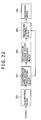
- FIG. 22 is a block diagram illustrating a third exemplary configuration of a receiving system applicable to receiving apparatuses.
- FIG. 23 is a block diagram illustrating an exemplary configuration of a computer.
- FIG. 5 there is shown a block diagram illustrating an exemplary configuration of a receiving apparatus practiced as the first embodiment of the present invention.
- the configuration of a receiving apparatus 30 shown in FIG. 5 differs from that shown in FIG. 1 mainly in that a repetition count control block 31 is arranged in place of the repetition count control block 12 and a BER computation block 32 is newly arranged.
- the receiving apparatus 30 controls the frequency of LDPC decoding by using, as an index, BER that is conditional information providing an index indicative of communication conditions affecting the power consumption at the time of decoding.
- the repetition count control block 31 is composed of a control block 41 and a frame start counter 42 .
- a frame start signal is entered.
- the control block 41 enters a decode enable signal into an LDPC decode block 11 on the basis of a BER supplied from the BER computation block 32 and a count value supplied from the frame start counter 42 , there by controlling the frequency of LDPC decoding.
- the control block 41 instructs the LDPC decode block 11 to output a decoding result.
- the control block 41 instructs the LDPC decode block 11 to execute decoding again before a log-likelihood ratio of a next frame is received; after a log-likelihood ratio of a next frame is received, the control block 41 instructs the LDPC decode block 11 to output a decoding result.
- the control block 41 controls the frame start counter 42 .
- the frame start counter 42 counts the number of times the frame start signal has been entered under the control of the control block 41 .
- the BER computation block 32 computes a BER on the basis of a decoding result supplied from the LDPC decode block 11 and a log-likelihood ratio entered from the outside, supplying a computed BER to the control block 41 of the repetition count control block 31 .
- This decode processing starts when a decode enable signal of H level is entered in the LDPC decode block 11 in response to a frame start signal of a start frame, for example.
- step S 31 the LDPC decode block 11 receives a log-likelihood ratio for each frame from the outside. Upon reception of the log-likelihood ratio, the decode enable signal goes L level.
- step S 32 the LDPC decode block 11 executes LDPC decoding by use of the received log-likelihood ratio.
- step S 33 the LDPC decode block 11 determines on the basis of a decoding result whether the LDPC decoding is successful or not.
- step S 33 If the LDPC decoding is found successful in step S 33 , then the LDPC decode block 11 supplies a decode successful flag to the control block 41 . Consequently, the control block 41 instructs the LDPC decode block 11 to output the decoding result. Next, in step S 34 , the LDPC decode block 11 outputs the decoding result.
- step S 35 the BER computation block 32 computes a BER on the basis of the log-likelihood ratio of the frame subject to the previous decoding and the decoding result supplied from the LDPC decode block 11 and supplies the obtained BER to the control block 41 .
- step S 36 the control block 41 determines whether the BER supplied from the BER computation block 32 is higher than a predetermined setting value that is preset. If the BER is found to be higher than the predetermined setting value in step S 36 , then the control block 41 determines whether a new frame start signal has been entered or not in step S 37 .
- step S 37 If no new frame start signal is found entered in step S 37 , then the control block 41 waits until a new frame start signal is entered.
- step S 37 if a new frame start signal is found entered in step S 37 , then the frame start counter 42 increments the count value by 1 under the control of the control block 41 in step S 38 . It should be noted that the initial value of the count value is 1.
- step S 39 the control block 41 determines whether the count value is equal to the predetermined setting value or not. If the count value is found to be not equal to the predetermined setting value, the processing procedure is returned to step S 37 . Then, until the count value becomes the predetermined setting value, the processing operations of step S 37 through step S 39 are repeated.
- step S 39 if the count value is found to be equal to the predetermined setting value in step S 39 , then the frame start counter 42 initializes the count value to 1 under the control of the control block 41 in step S 40 .
- the control block 41 supplies a decode enable signal of H level to the LDPC decode block 11 , returning the processing procedure to step S 31 . Consequently, the LDPC decoding for the log-likelihood ratio of a frame that is the (setting value ⁇ 1)th frame from the frame subject to the previous decoding is executed.
- step S 41 determines in step S 41 whether a new frame start signal has been entered or not. If no new frame start signal is found entered in step S 41 , then the control block 41 waits until a new frame start signal is entered.
- step S 41 if a new frame start signal is found entered in step S 41 , then the control block 41 supplies a decode enable signal of H level to the LDPC decode block 11 .
- the processing procedure is returned to step S 31 .
- the LDPC decoding for the log-likelihood ratio of a frame next to the frame subject to the previous decoding is executed.
- step S 33 If the LDPC decoding is found unsuccessful in step S 33 , then the LDPC decode block 11 supplies a decode unsuccessful signal to the control block 41 .
- step S 42 the control block 41 determines whether a new frame start signal has been entered or not.
- step S 42 If no new frame start signal is found entered in step S 42 , then the control block 41 instructs the LDPC decode block 11 to execute decoding and returns the processing procedure to step S 32 . Next, the processing operations of steps S 32 , S 33 , and S 42 are repeated until the LDPC decoding is successful or a new frame start signal is entered.
- step S 42 if a new frame start signal is found entered in step S 42 , then the control block 41 instructs the LDPC decode block 11 to output a decoding result.
- step S 43 the LDPC decode block 11 outputs a decoding result in response to the instruction supplied from the control block 41 .
- the receiving apparatus 30 is able to repeat the LDPC decoding until the LDPC decoding is successful during a period of time where a frame start signal of a frame next to the frame subject to the current decoding.
- step S 44 the BER computation block 32 computes a BER on the basis of the log-likelihood ratio of the frame subject to the previous decoding and the decoding result supplied from the LDPC decode block 11 and supplies the obtained BER to the control block 41 .
- step S 45 the control block 41 determines whether the BER supplied from the BER computation block 32 is higher than a preset predetermined setting value. If the BER is found to be higher than the preset determined setting value in step S 45 , then the processing procedure goes to step S 38 to execute the subsequent processing.
- step S 45 the control block 41 enters a decode enable signal of H level into the LDPC decode block 11 , returning the processing procedure to step S 31 .
- the LDPC decoding for the log-likelihood ratio of a frame next to the frame subject to the previous decoding is executed.
- FIG. 7 there is shown a timing chart indicative of operations timings of the receiving apparatus 30 in the case where the BER is higher than a predetermined setting value.
- the control block 41 enters a decode enable signal of H level into the LDPC decode block 11 .
- This causes the LDPC decode block 11 to receive the log-likelihood ratio of the first frame and executes the LDPC decoding on this log-likelihood ratio.
- the count value of the frame start counter 42 is 1 as initial value. It should be noted that, when the reception of the log-likelihood ratio of the first frame has been completed, the decode enable signal goes L level.
- the LDPC decoding of the first frame is unsuccessfully repeated until the reception of the log-likelihood ratio of a second frame next to the first frame and a decoding result is outputted. Also, in the example shown in FIG. 7 , the BER is higher than the setting value, so that, when the frame start signal of the second frame is entered, the count value is incremented to 2.
- the log-likelihood ratio of the second frame is received as shown in FIG. 7 but no LDPC decoding is executed because the count value is 2. Then, when the log-likelihood ratio of a third frame is entered, the log-likelihood ratio of the third frame is received and the count value is incremented by 1 to 3. In this case, too, the count value is not 4, so that the LDPC decoding of the third frame is not executed.
- the log-likelihood ratio of the fourth frame is received and the count value is incremented by 1 to 4.
- the decode enable signal goes H level and, at the same time, the count value is initialized to 1, thereby executing the LDPC decoding of the fourth frame.
- the LDPC decoding is executed on every three frames until the BER goes below a predetermined setting value as described above. That is, the LDPC decoding of the first frame, the fourth frame, . . . , (3n+1)th frame (n being an integer greater than or equal to 0) is executed.
- the power consumption of the receiving apparatus is dominant at the time of LDPC decoding, so that the receiving apparatus 30 executes the LDPC decoding on every three frames, thereby reducing the power consumption to 1/3 of a situation in which the LDPC decoding is executed on every frame.
- the receiving apparatus 30 executes the LDPC decoding at predetermined intervals, so that the receiving apparatus 30 is able to compute the BER at predetermined intervals.
- the LDPC decoding can be restarted. Therefore, the receiving apparatus 30 is able to hold down the power consumption in bad conditions when the BER is in a low condition, namely, while LDPC codes in good conditions are LDPC-decoded.
- the frequency of LDPC codes in the case where the BER is higher than a predetermined setting value is not obviously limited to the frequency of every three frames. For example, if the frequency of LDPC decoding is every 10 frames, the power consumption is reduced to 1/10 of the case shown in FIG. 4 .
- FIG. 8 there is shown a relation between power consumption and BER.
- the horizontal axis is representative of C/N (Carrier to Noise ratio) (dB) of transmission path and the vertical axis is representative of the power consumption and BER at the time of LDPC decoding of the log-likelihood ratio.
- the receiving apparatus 30 receives an LDPC code, decodes the received LDPC code, and, on the basis of the BER that is conditional information, controls the frequency of the LDPC decoding, so that the receiving apparatus 30 is able to hold down the power consumption in bad conditions while decoding LDPC codes in good conditions.
- noise information such as signal-to-noise ratio (SNR), C/N, noise power, and noise amount, that can be computed by a demodulator (not shown) arranged on the preceding stage of the receiving apparatus 30 can be used.
- SNR signal-to-noise ratio
- C/N C/N
- noise power noise amount
- the correlation between noise information and BER may not be constant depending on modulation scheme, code rate, and type of external disturbance, for example.
- C/N code rate
- BER type of external disturbance
- FIG. 9 there is shown a block diagram illustrating an exemplary configuration of a receiving apparatus practiced as the second embodiment of the invention.
- the configuration of a receiving apparatus 50 shown in FIG. 9 differs from that shown in FIG. 1 mainly in that a repetition count control block 51 is arranged in place of the repetition count control block 12 .
- the receiving apparatus 50 uses the count of unsuccessful LDPC decoding until a new log-likelihood ratio is received (this count is hereafter referred to as a decode unsuccessful count) as conditional information that provides an index of frequency control.
- the decode unsuccessful count increases as the error in decoding results increases, so that there is a correlation between the decode unsuccessful count and BER.
- the repetition count control block 51 shown in FIG. 9 is composed of a control block 61 , frame start counters 62 and 63 , and a decode unsuccessful counter 64 .
- a frame start signal is entered.
- the control block 61 controls the frequency of decoding by entering a decode enable signal into an LDPC decode block 11 on the basis of the count values of the frame start counters 62 and 63 , and the decode unsuccessful counter 64 .
- the control block 61 instructs the LDPC decode block 11 to output a decoding result.
- the control block 61 instructs the LDPC decode block 11 to execute decoding again before the log-likelihood ratio of a next frame is received; when the log-likelihood ratio of the next frame is received, the control block 61 instructs the LDPC decode block 11 to output a decoding result.
- control block 61 controls the frame start counter 63 on the basis of a count value of the frame start counter 62 and a decode suppression enable signal indicative of the suppression or non-suppression of decode frequency supplied from the decode unsuccessful counter 64 .
- control block 61 controls the decode unsuccessful counter 64 on the basis of a count value of the frame start counter 62 .
- the frame start counter 62 counts the input count of frame start signals.
- the frame start counter 63 counts the input count of a frame start signal under the control of the control block 61 .
- the decode unsuccessful counter 64 counts a count of decode unsuccessful flags supplied from the LDPC decode block 11 under the control of the control block 61 .
- the decode unsuccessful counter 64 supplies a decode suppression enable signal to the control block 61 on the basis of the count value.
- This decode processing starts when a decode enable signal of H level is entered in the LDPC decode block 11 in response to a frame start signal of the start frame, for example.
- step S 61 the LDPC decode block 11 receives the log-likelihood ratio for each frame from the outside. After the reception, a decode enable signal goes L level.
- step S 62 the LDPC decode block 11 executes the LDPC decoding by use of the received log-likelihood ratio.
- step S 63 the LDPC decode block 11 determines on the basis of a decoding result whether the LDPC decoding is successful or not.
- step 63 the LDPC decode block 11 supplies a decode successful flag to the control block 61 .
- the control block 61 instructs the LDPC decode block 11 to output a decoding result.
- step S 64 the LDPC decode block 11 outputs the decoding result.
- step S 65 the control block 61 determines whether a new frame start signal has been entered or not. If no new frame start signal is found entered in step S 65 , then the control block 61 waits until a new frame start signal is entered.
- step S 65 if a new frame start signal is found entered in step S 65 , then the frame start counter 62 increments count value A by 1 in step S 66 , upon which the processing procedure goes to step S 71 . It should be noted that the initial value of count value A is 1.
- step S 63 If the LDPC decoding is found unsuccessful in step S 63 , then the LDPC decode block 11 supplies a decode unsuccessful flag to the control block 61 .
- step S 67 the control block 61 determines whether a new frame start signal has been entered or not. If no new frame start signal is found entered in step S 67 , the processing procedure returns to step S 62 , in which the processing operations of steps S 62 , S 63 , and S 67 are repeated until the LDPC decoding is successful or a new frame start signal is entered.
- step S 67 If a new frame start signal is found entered in step S 67 , then the LDPC decode block 11 outputs a decoding result in step S 68 .
- step S 69 the decode unsuccessful counter 64 increments count value B by 1. It should be noted that the initial value of count value B is 0.
- step S 70 the frame start counter 62 increments count value A by 1, upon which the processing procedure goes to step S 71 .
- step S 71 the frame start counter 62 determines whether count value A is preset predetermined setting value or not. If count value A is found to be a predetermined setting value in step S 71 , then the frame start counter 62 initializes count value A to 1 in step S 72 .
- step S 73 the decode unsuccessful counter 64 determines count value B is higher than a preset predetermined setting value or not. If count value B is found to be higher than the predetermined setting value in step S 73 , then the decode unsuccessful counter 64 sets the level of a decode suppression enable signal to H level indicative of the suppression of signal frequency in step S 74 . This decode suppression enable signal is entered in the control block 61 .
- step S 75 the decode unsuccessful counter 64 initializes count value B to 0.
- step S 76 the control block 61 determines whether a new frame start signal has been entered or not. If no new frame start signal is found entered in step S 76 , the control block 61 waits until a new frame start signal is entered.
- step S 76 if a new frame start signal is found entered in step S 76 , then the frame start counter 63 increments count value C by 1 in step S 77 . It should be noted that the initial value of count value C is 1.
- step S 78 the frame start counter 63 determines whether count value C is a preset predetermined setting value. If count value C is found not to be the predetermined setting value in step 78 , the processing procedure returns to step S 76 , in which the processing operations of steps S 76 through S 78 are repeated until count value C becomes the predetermined setting value.
- step S 78 if count value C is found to be the predetermined setting value in step S 78 , then the frame start counter 63 initializes count value C to 1 in step S 79 , upon which the processing procedure returns to step S 61 . Consequently, the LDPC decoding for the log-likelihood ratio of a frame that is the (setting value ⁇ 1)th frame from the frame subject to the previous decoding is executed.
- the frequency of LDPC decoding is controlled such that the LDPC decoding is executed on every (setting value ⁇ 1) frames.
- the decode unsuccessful counter 64 sets the level of a decode suppression enable signal to be entered into the control block 61 to L level indicative of non-suppression of decode frequency.
- step S 81 the decode unsuccessful counter 64 initializes count value B to 0, upon which the processing procedure returns to step S 61 . Consequently, the LDPC decoding for the log-likelihood ratio of a frame next to the frame subject to the previous decoding. That is, in the receiving apparatus 50 , if a ratio of decode unsuccessful frames to a predetermined number of frames is lower than a predetermined ratio, the LDPC decoding is executed on every frame.
- step S 82 determines in step S 82 whether the level of a decode suppression enable signal entered from the decode unsuccessful counter 64 is H level or not. If the level of a decode suppression enable signal is found to be H level in step S 82 , the procedure goes to step S 76 , in which the subsequent processing operations are executed therefrom. That is, the frequency of the LDPC decoding is controlled such that the LDPC decoding is executed on every (setting value ⁇ 1) frames.
- step S 82 if the level of a decode suppression enable signal is found to be L level in step S 82 , then the processing procedure returns to step S 61 , in which the subsequent processing operations are executed therefrom. That is, the LDPC decoding is executed on every frame.
- the frequency of LDPC decoding is controlled for each of the predetermined number of frames in the receiving apparatus 50 .
- FIG. 11 there is shown a timing chart indicative of operation timings of the frame start counters 62 and 63 and the decode unsuccessful counter 64 in the receiving apparatus 50 .
- the receiving apparatus 50 failed executing the LDPC decoding of the first through third frames. It is assumed that the setting value for use in the determination of a count value of the frame start counter 62 be 4 and the setting value for use in the determination of a count value of the decode unsuccessful counter 64 be 2.
- the frame start counter 62 increments count value A by 1 from initial value 1 to setting value 4 and initializes count value A to 1 when count value A has reached setting value 4.
- the decode unsuccessful counter 64 increments count value B by 1 from initial value 0. In the example shown in FIG. 11 , the decoding of the first through third frames was unsuccessful, so that the count value B is incremented up to 3 and initialized to 0 when count value A has reached 4.
- count value A When count value A has reached 4, count value B is 3, higher than setting value 2, so that the level of the decode suppression enable signal goes H level. It should be noted that, in the example shown in FIG. 11 , the initial level of the decode suppression enable signal is L level.
- the frame start counter 63 increments count value C by 1 from initial value 1 every time a frame start signal is entered. At this moment, count value A of the frame start counter 62 and count value B of the decode unsuccessful counter 64 remain unchanged at the initial values.
- FIG. 12 and FIG. 13 are timing charts indicative of operation timings of the control block 61 of the receiving apparatus 50 .
- FIG. 12 shows operation timings at the time when the level of a decode suppression enable signal goes from L level to H level.
- FIG. 13 shows operation timings at the time when the level of the decode suppression enable signal goes from H level to L level.
- the frequency of decoding changes from (1/1) to 1/(setting value ⁇ 1) (1/10 in the example shown in FIG. 12 ) for each frame.
- the frequency of decoding is changed from 1/(setting value ⁇ 1) (1/10 in the example shown in FIG. 13 ) to (1/1) for each frame.
- a predetermined setting value for use in the determination of count value C may be changed from time to time and the frequency of decoding may be changed stepwise.
- the frequency of decoding is gradually changed to 1/1 to 1/2 to 1/4 to 1/10 in this order as shown in FIG. 14 , for example.
- the level of the decode suppression enable signal is changed from H level to L level, the frequency of decoding is gradually changed to 1/10 to 1/4 to 1/2 to 1/1 in this order as shown in FIG. 15 , for example. Therefore, in this case, an abrupt power supply variation can be suppressed.
- This technique of gradually changing the frequency of decoding is applicable to the first embodiment of the invention.
- the receiving apparatus 50 described above uses the unsuccessful count of LDPC decoding as conditional information; it is also practicable to use, as the conditional information, such statistical values as decoding count and integrated value of decoding counts that are correlated with BER.
- FIG. 16 there is shown a block diagram illustrating an exemplary configuration of a receiving apparatus practiced as the third embodiment of the invention.
- the configuration of a receiving apparatus 70 shown in FIG. 16 differs from that shown in FIG. 5 mainly in that a repetition count control block 71 is arranged in place of the repetition count control block 31 .
- the receiving apparatus 70 controls the speed of LDPC decoding on the basis of a free time in which LDPC decoding is not executed, from the output of a decoding result of a predetermined frame to the reception of a log-likelihood ratio of a next frame.
- the repetition count control block 71 is composed of a control block 81 and a frame start counter 42 .
- a frame start signal is entered.
- control block 81 On the basis of a BER supplied from a BER computation block 32 and a count value of the frame start counter 42 , the control block 81 enters a decode enable signal into an LDPC decode block 11 to control the frequency of decoding.
- the control block 81 instructs the LDPC decode block 11 to output a decoding result.
- the control block 81 instructs the LDPC decode block 11 to execute decoding again before the log-likelihood ratio of a next frame is received and further instructs the LDPC decode block 11 to output a decoding result when the log-likelihood ratio of the next frame is received.
- control block 81 computes a free time on the basis of a reception interval of the log-likelihood ratio, namely, an input interval of a frame start signal, and the output timing of a decoding result. On the basis of the obtained free time, the control block 81 controls the frequency of an operation clock of an LDPC decode, thereby controlling decoding speed.
- FIG. 17 there is shown a flowchart indicative of decoding speed control processing to be executed by the receiving apparatus 70 .
- This decoding speed control processing starts when the frame start signal of a start frame is entered in the receiving apparatus 70 .
- step S 101 the control block 81 determines whether the LDPC decode block 11 has been instructed to output a decoding result. If the LDPC decode block 11 is found not instructed to output a decoding result in step S 101 , then the control block 81 waits until the LDPC decode block 11 is instructed to output a decoding result.
- step S 101 determines whether the reception by the LDPC decode block 11 of the log-likelihood ratio of a frame next to the frame subject to the previous decoding has ended or not. If the reception is found not ended in step S 102 , then the control block 81 waits until the reception ends.
- step S 103 the control block 81 computes, as a free time, a period of time from instructing the LDPC decode block 11 to output a decoding result to the end of reception of the log-likelihood ratio of a frame next to the frame subject to the previous decoding.
- step S 104 the control block 81 determines whether the computed free time is within a predetermined range set in advance. If the free time is found within a predetermined range in step S 104 , the control block 81 determines that the decoding speed is optimum, upon which the processing procedure returns to step S 101 .
- step S 104 determines in step S 105 whether the free time is smaller than the predetermined range or not. If the free time is found smaller than the predetermined range in step S 105 , then the control block 81 determines that the decoding speed is slow and, in step S 106 , raises the frequency of the operation clock of the LDPC decoding to be executed by the LDPC decode block 11 . Next, the processing procedure returns to step S 101 to repeat the above-mentioned processing operations therefrom.
- step S 105 If the free time is found greater than the predetermined range in step S 105 , then the control block 81 determines that the decoding speed is fast and, in step S 107 , lowers the frequency of the operation clock of the LDPC decode block 11 . Next, the processing procedure returns to step S 101 to repeat the processing operations therefrom.
- the decoding processing by the receiving apparatus 70 is substantially the same as that by the receiving apparatus 30 shown in FIG. 6 , so that the description of the decoding processing by the receiving apparatus 70 is skipped.
- FIG. 18 and FIG. 19 illustrate the effects to be achieved by the receiving apparatus 70 .
- FIG. 18 there is shown a timing chart indicative of operation timings of the receiving apparatus that does not control the speed of LDPC decoding.
- FIG. 19 there is shown a timing chart indicative of operation timings of the receiving apparatus 70 that controls the speed of LDPC decoding.
- LDPC decoding is executed immediately after the end of reception of the log-likelihood ratio, thereby increasing the power consumption; however, LDPC decoding is not executed during a period from a successful decoding to the capture of the log-likelihood ratio of a next frame, thereby causing the power consumption to be low.
- a difference of the power consumption is P between the power consumption during time t from the reception of the log-likelihood ratio of the first frame and the power consumption during a period from a successful decoding to the reception of the log-likelihood ratio of a next frame.
- the receiving apparatus 70 that controls the speed of LDPC decoding changes the frequency of the operation clock of the LDPC decode block 11 such that the free time of the frame subject to the current decoding gets within a predetermined range. That is, the receiving apparatus 70 averages the operations of LDPC decoding by use of a time obtained by subtracting the time in a predetermined range from the free time.
- the frequency of the operation clock is made 1/4 times the frequency of the operation clock in the case shown in FIG. 18 . Consequently, a time from the reception of the log-likelihood ratio of the first frame to the output of a decoding result is 4t, thereby averaging the power consumption within 4t time to P/4. As a result, the peak value of the power consumption can be lowered while a total amount of the power consumption remains unchanged and, at the same time, the variation in power supply can be held down.
- the receiving apparatus 70 is able to receive a log-likelihood ratio to LDPC-decode the received log-likelihood ratio and, on the basis of the reception interval of this log-likelihood ratio, control the speed of LDPC decoding, thereby suppressing the drastic change in power consumption.
- the speed of LDPC decoding is controlled on the basis of the free time of the frame subject to the previous decoding; however, it is also practicable to control the speed of LDPC decoding on the basis of a log-likelihood ratio receiving interval of each frame.
- This receiving interval can be computed trough a demodulator, not shown, arranged in the preceding stage of the receiving apparatus 70 from the number of symbols per frame and a symbol rate.
- the receiving apparatus 70 suppresses power supply variation by controlling the decoding speed by controlling the frequency of the operation clock of the LDPC decode block 11 ; however, the method of suppressing power supply variation is not limited thereto.
- power supply variations may be suppressed by controlling the power supply voltage of the LDPC decode block 11 or controlling the voltage to be applied to a substrate terminal of a transistor making up the LDPC decode block 11 .
- the method of controlling the decoding speed described with respect to the third embodiment of the invention is also applicable to a receiving apparatus that does not control the frequency of decoding.
- the speed of decoding may be changed stepwise like the frequency of decoding described above.
- the frequency of the operation clock is changed from the normal frequency to 1/4 times thereof, the frequency of the operation clock is changed stepwise to 1, 1/2, and 1/4 times the normal frequency in this order.
- the frequency of the operation clock is changed from 1/4 times the normal frequency to the normal frequency, the frequency of the operation clock is changed stepwise to 1/4, 1/2, and 1 times the normal frequency in this order.
- FIG. 20 there is shown a block diagram illustrating an exemplary first configuration of a receiving system applicable to the receiving apparatuses 30 , 50 , and 70 described above.
- the receiving system is composed of an acquisition block 201 , a transmission path decode processing block 202 , and an information source decode processing block 203 .
- the acquisition block 201 acquires a signal that at least includes an LDPC code obtained by LDPC-decoding subject data, such as program's image data and audio data.
- the acquisition block 201 acquires the signal via a transmission path, not shown, such as terrestrial digital broadcasting, satellite broadcasting, CATV (Cable Television) network, the Internet, or other networks and supplies the acquired signal to the transmission path decode processing block 202 .
- a transmission path not shown, such as terrestrial digital broadcasting, satellite broadcasting, CATV (Cable Television) network, the Internet, or other networks and supplies the acquired signal to the transmission path decode processing block 202 .
- the acquisition block 201 is configured by a tuner or STB (Set Top Box), for example. If the signal to be acquired by the acquisition block 201 is transmitted in a multicast manner as with IPTV (Internet Protocol Television) from a Web server, for example, the acquisition block 201 is configured by a network interface, such as NIC (Network Interface Card), for example.
- NIC Network Interface Card
- the transmission path decode processing block 202 executes transmission path decode processing at least including the processing of correcting an error caused on the transmission path on the signal acquired by the acquisition block 201 via transmission path and supplies a resultant signal to the information source decode processing block 203 .
- the signal acquired by the acquisition block 201 via transmission path is a signal obtained by at least executing error correction coding for correcting an error caused on the transmission path. So, the transmission path decode processing block 202 executes transmission path decode processing, such as error correction processing for example, on this signal.
- the error correction coding includes LDPC coding and Reed-Solomon coding, for example.
- LDPC coding for the error correction code, at least LDPC coding is executed.
- the transmission path decode processing may include the demodulation of modulated signals, for example.
- the information source decode processing block 203 executes information source decode processing including at least the processing of decompressing compressed information to the original information onto the signal with the transmission path decode signal executed.
- the signal acquired by the acquisition block 201 via transmission path may have been executed with compression coding for compression information to reduce the amount of data i.e. image and audio data.
- the information source decode processing block 203 executes information source decoding processing, such as decompression processing for decompressing the compressed information to the original information, onto the signal executed with transmission path decode processing.
- the information source decode processing block 203 does not execute the decompression processing for decompressing the compressed information to the original information.
- the decompression processing includes MPEG (Moving Picture Experts Group phase) decoding for example.
- the information source decode processing includes descrambling, for example, in addition to the decompression processing.
- the acquisition block 201 acquires, via transmission path, a signal compressed by MPEG coding for example in image and audio data for example, this signal further being executed with error correction processing such as LDPC coding for example, and supplies the compressed and error-corrected signal to the transmission path decode processing block 202 .
- error correction processing such as LDPC coding
- the transmission path decode processing block 202 executes, as transmission decode processing, the processing similar to that of the receiving apparatuses 30 , 50 , and 70 onto the LDPC code supplied from the acquisition block 201 , for example.
- the signal obtained as a result of the transmission path decode processing is supplied to the information source decode processing block 203 .
- the information source decode processing block 203 executes information source decode processing, such as MPEG decoding, on the signal supplied from the transmission path decode processing block 202 and outputs a resultant image or audio.
- information source decode processing such as MPEG decoding
- the receiving system configured as described above is applicable to a television tuner for receiving television broadcasting as digital broadcasting, for example.
- the acquisition block 201 , the transmission path decode processing block 202 , and the information source decode processing block 203 may be each configured as a discrete device (a hardware device such as an IC (Integrated Circuit) for example or a software module).
- Such a set may include one composed of the acquisition block 201 and the transmission path decode processing block 202 , another composed of the transmission path decode processing block 202 and the information source decode processing block 203 , and still another composed of acquisition block 201 and the transmission path decode processing block 202 , and the information source decode processing block 203 , for example.
- FIG. 21 there is shown a block diagram illustrating a second exemplary configuration of a receiving system applicable to the receiving apparatuses 30 , 50 , and 70 described above.
- the receiving system shown in FIG. 21 is substantially common to the receiving system shown in FIG. 20 in having the acquisition block 201 , the transmission path decode processing block 202 , and information source decode processing block 203 and is different from the receiving system shown in FIG. 20 in an output block 204 .
- the output block 204 is a display apparatus for displaying images or a loudspeaker for sounding audio data, outputting image and audio data as a signal outputted from the information source decode processing block 203 . That is, the output block 204 displays images or outputs audio data.
- the receiving system shown in FIG. 21 configured as described above is applicable to television receivers for receiving television broadcasting as digital broadcasting and radio receivers for receiving radio broadcasting.
- the signal outputted from the transmission path decode processing block 202 is supplied to the output block 204 .
- FIG. 22 there is shown a block diagram illustrating a third exemplary configuration of a receiving system applicable to the receiving apparatuses 30 , 50 , and 70 described above.
- the receiving system shown in FIG. 22 is substantially common to the receiving system shown in FIG. 21 in having the acquisition block 201 and the transmission path decode processing block 202 .
- the receiving system shown in FIG. 22 does not have the information source decode processing block 203 but has a recording control block 205 and a recording media 206 , which is a difference from the receiving system shown in FIG. 21 .
- the recording control block 205 controls the recording of a signal (a TS packet of MPEG TS (Transport Stream) for example) outputted from the transmission path decode processing block 202 onto the recording media 206 , such as an optical disk, a hard disk (or a magnetic disk), or a flash memory.
- a signal a TS packet of MPEG TS (Transport Stream) for example
- the recording media 206 such as an optical disk, a hard disk (or a magnetic disk), or a flash memory.
- the receiving system configured as described above is applicable to recorders and the like for recording television broadcasting.
- the receiving system can be configured by the information source decode processing block 203 , which can make the recording control block 205 record a signal with the information source decode processing executed, namely, image and audio data obtained by decoding, onto the recording media 206 .
- a computer shown in FIG. 23 can be used for at least a part of the receiving system that includes the receiving apparatuses 30 , 50 , and 70 described above.
- a CPU (Central Processing Unit) 301 executes various processing operations as instructed by programs recorded to a ROM (Read Only Memory) 302 .
- the CPU 301 also executes various processing operations as instructed by programs stored in a storage block 308 and loaded into a RAM (Random Access Memory) 303 .
- the RAM 303 also stores data and so on necessary for the CPU 301 to execute various processing operations.
- the CPU 301 , the ROM 302 , and the RAM 303 are interconnected through a bus 304 .
- This bus 304 is also connected with an input/output interface 305 .
- the input/output interface 305 is connected with an input block 306 composed of a keyboard and a mouse for example, and an output block 307 composed of a display monitor for example.
- the input/output interface 305 is also connected with a storage block 308 composed of a hard disk drive for example and a communication block 309 composed of a modem and a terminal adaptor for example.
- the communication block 309 controls communication that is executed between other apparatuses, not shown, via a network including the Internet.
- the input/output interface 305 is also connected with a drive 310 as required, on which a removable media 311 , such as a magnetic disk, an optical disk, a magneto-optical disk or a semiconductor device, is appropriately loaded. Then, computer programs read from the removal media 311 are installed in the storage block 308 as required.
- a removable media 311 such as a magnetic disk, an optical disk, a magneto-optical disk or a semiconductor device
- the programs constituting the software are installed in a computer which is built in dedicated hardware equipment or installed, from a network or recording media, into a general-purpose personal computer for example in which various programs may be installed for the execution of various functions.
- the above-mentioned recording media is configured not only by the removable media 311 such as a magnetic disk (including a floppy disk), an optical disk (including CD-ROM (Compact Disk Read Only Memory), DVD (Digital Versatile Disk), a magneto-optical disk (including MD (Mini Disk) (trademark)), or a semiconductor memory recorded with programs for distribution of programs to users separately from the apparatus main, but also by the ROM 302 recorded with programs and a hard disk drive recorded with programs and included in the storage block 308 that are provided to users as incorporated in the apparatus main as shown in FIG. 23 .
- the removable media 311 such as a magnetic disk (including a floppy disk), an optical disk (including CD-ROM (Compact Disk Read Only Memory), DVD (Digital Versatile Disk), a magneto-optical disk (including MD (Mini Disk) (trademark)), or a semiconductor memory recorded with programs for distribution of programs to users separately from the apparatus main, but also by the ROM 302 recorded with programs and
- steps for describing each program recorded in recording media include not only the processing operations which are sequentially executed in a time-dependent manner but also the processing operations which are executed concurrently or discretely.
- system denotes an entire apparatus configured by a plurality of component units.
Abstract
Description
Claims (11)
Applications Claiming Priority (2)
| Application Number | Priority Date | Filing Date | Title |
|---|---|---|---|
| JPP2009-131260 | 2009-05-29 | ||
| JP2009131260A JP5445829B2 (en) | 2009-05-29 | 2009-05-29 | Receiving apparatus, receiving method, program, and receiving system |
Publications (2)
| Publication Number | Publication Date |
|---|---|
| US20100306616A1 US20100306616A1 (en) | 2010-12-02 |
| US8464124B2 true US8464124B2 (en) | 2013-06-11 |
Family
ID=42470829
Family Applications (1)
| Application Number | Title | Priority Date | Filing Date |
|---|---|---|---|
| US12/783,291 Expired - Fee Related US8464124B2 (en) | 2009-05-29 | 2010-05-19 | Receiving apparatus, receiving method and program, and receiving system |
Country Status (4)
| Country | Link |
|---|---|
| US (1) | US8464124B2 (en) |
| EP (1) | EP2256974B1 (en) |
| JP (1) | JP5445829B2 (en) |
| CN (1) | CN101902229B (en) |
Families Citing this family (9)
| Publication number | Priority date | Publication date | Assignee | Title |
|---|---|---|---|---|
| US8433970B2 (en) | 2010-03-31 | 2013-04-30 | Silicon Laboratories Inc. | Techniques to control power consumption in an iterative decoder by control of node configurations |
| US8555131B2 (en) | 2010-03-31 | 2013-10-08 | Silicon Laboratories Inc. | Techniques to control power consumption in an iterative decoder by control of node configurations |
| US8341486B2 (en) * | 2010-03-31 | 2012-12-25 | Silicon Laboratories Inc. | Reducing power consumption in an iterative decoder |
| US8237869B2 (en) | 2010-03-31 | 2012-08-07 | Silicon Laboratories Inc. | Multi-standard digital demodulator for TV signals broadcast over cable, satellite and terrestrial networks |
| US8543891B2 (en) | 2011-09-21 | 2013-09-24 | Apple Inc. | Power-optimized decoding of linear codes |
| SG10201707007QA (en) | 2015-10-13 | 2017-09-28 | Huawei Tech Co Ltd | Decoding device and method and signal transmission system |
| US10411833B2 (en) * | 2016-07-29 | 2019-09-10 | Qualcomm Incorporated | Early termination techniques for successive decoding processes |
| CN106656417B (en) * | 2016-10-27 | 2019-11-19 | 晶晨半导体(上海)股份有限公司 | A kind of searcher solving the positive and negative frequency spectrum of dtmb single carrier |
| CN110895911A (en) * | 2018-09-12 | 2020-03-20 | 晨星半导体股份有限公司 | Circuit applied to display device and control method of decoding circuit |
Citations (9)
| Publication number | Priority date | Publication date | Assignee | Title |
|---|---|---|---|---|
| JP2007081640A (en) | 2005-09-13 | 2007-03-29 | Matsushita Electric Ind Co Ltd | Turbo decoder and turbo decoding method |
| US20070113149A1 (en) | 2005-10-26 | 2007-05-17 | Broadcom Corporation | Power savings technique for iterative decoding |
| JP2008544692A (en) | 2005-06-27 | 2008-12-04 | トムソン ライセンシング | Method and apparatus for reducing power in an iterative decoder |
| JP2009038707A (en) | 2007-08-03 | 2009-02-19 | Sumitomo Electric Ind Ltd | Decoder, receiver, decoding method of encoded data, and communication system |
| US20090049362A1 (en) | 2007-08-15 | 2009-02-19 | Beceem Communications, Inc. | Method and system for decoding a data burst in a communication system |
| US7783950B2 (en) * | 2005-09-22 | 2010-08-24 | Rohm Co., Ltd. | Data writing apparatus and a storage system |
| US7876670B2 (en) * | 2005-02-03 | 2011-01-25 | Agency For Science, Technology And Research | Method for transmitting data, method for receiving data, transmitter, receiver, and computer program products |
| US7882415B2 (en) * | 2004-12-29 | 2011-02-01 | Intel Corporation | 3-Stripes gilbert low density parity-check codes |
| US8074142B2 (en) * | 2005-09-26 | 2011-12-06 | Nec Corporation | Decoding device and receiving device |
Family Cites Families (4)
| Publication number | Priority date | Publication date | Assignee | Title |
|---|---|---|---|---|
| JP3196835B2 (en) * | 1998-07-17 | 2001-08-06 | 日本電気株式会社 | Viterbi decoding method and Viterbi decoder |
| CA2563642C (en) * | 2004-08-10 | 2013-10-01 | Samsung Electronics Co., Ltd. | Apparatus and method for encoding and decoding a block low density parity check code |
| JP4487213B2 (en) * | 2007-10-19 | 2010-06-23 | ソニー株式会社 | Decoding apparatus and method, and program |
| JP4355018B2 (en) * | 2008-08-25 | 2009-10-28 | 富士通マイクロエレクトロニクス株式会社 | Method for controlling error correction processing apparatus |
-
2009
- 2009-05-29 JP JP2009131260A patent/JP5445829B2/en not_active Expired - Fee Related
-
2010
- 2010-05-06 EP EP10004802.4A patent/EP2256974B1/en not_active Not-in-force
- 2010-05-19 US US12/783,291 patent/US8464124B2/en not_active Expired - Fee Related
- 2010-05-21 CN CN201010184937.0A patent/CN101902229B/en not_active Expired - Fee Related
Patent Citations (10)
| Publication number | Priority date | Publication date | Assignee | Title |
|---|---|---|---|---|
| US7882415B2 (en) * | 2004-12-29 | 2011-02-01 | Intel Corporation | 3-Stripes gilbert low density parity-check codes |
| US7876670B2 (en) * | 2005-02-03 | 2011-01-25 | Agency For Science, Technology And Research | Method for transmitting data, method for receiving data, transmitter, receiver, and computer program products |
| JP2008544692A (en) | 2005-06-27 | 2008-12-04 | トムソン ライセンシング | Method and apparatus for reducing power in an iterative decoder |
| US20090094470A1 (en) | 2005-06-27 | 2009-04-09 | Wen Gao | Method and apparatus for power reduction in iterative decoders |
| JP2007081640A (en) | 2005-09-13 | 2007-03-29 | Matsushita Electric Ind Co Ltd | Turbo decoder and turbo decoding method |
| US7783950B2 (en) * | 2005-09-22 | 2010-08-24 | Rohm Co., Ltd. | Data writing apparatus and a storage system |
| US8074142B2 (en) * | 2005-09-26 | 2011-12-06 | Nec Corporation | Decoding device and receiving device |
| US20070113149A1 (en) | 2005-10-26 | 2007-05-17 | Broadcom Corporation | Power savings technique for iterative decoding |
| JP2009038707A (en) | 2007-08-03 | 2009-02-19 | Sumitomo Electric Ind Ltd | Decoder, receiver, decoding method of encoded data, and communication system |
| US20090049362A1 (en) | 2007-08-15 | 2009-02-19 | Beceem Communications, Inc. | Method and system for decoding a data burst in a communication system |
Non-Patent Citations (7)
| Title |
|---|
| Darabiha, A. "Power Reduction Techniques for LDCP Decoders", IEEE Journal of Solid-State Circuits, IEEE Service Center, Piscataway, NJ. vol. 43, No. 8, Aug. 1, 2008, pp. 1835-1845. |
| European Search Report issued Sep. 28, 2011 in Munich for corresponding European patent application No. EP 10 00 4802. |
| Gilbert, F. "Lower Power Inplementation of a Turbo-Decoder on Programmable Architectures" Proc. Design Automation Conference 2001, Piscataway, NJ. Jan. 20, 100', pp. 400-403. |
| Levin, D. "Lazy Scheduling for LDPC Decoding", IEEE Communications Letters, IEEE Service Center, Piscataway, NJ, vol. 11, No. 1, Jan. 1, 2007, pp. 70-72. |
| Mar. 4, 2013, EPO communication issued in related application No. EP10 004 802.4. |
| Tzu-Chieh, K. "A Flexible Decoder IC for WiMax QC-LDPC Codes", Proc. 2008 IEEE Custom Integrated Circuits Conference (CICC 2008), IEEE, Piscataway, NJ. Sep. 21, 2008, pp. 527-530. |
| Wang et al., Minimum-Energy LDPC Decoder for Real-Time Mobile Application, Proc. IEEE Design, Automation & Test in Europe Conference & Exhibition 2007, Apr. 1, 2007, pp. 1-6. |
Also Published As
| Publication number | Publication date |
|---|---|
| EP2256974B1 (en) | 2014-01-01 |
| EP2256974A2 (en) | 2010-12-01 |
| CN101902229B (en) | 2014-06-18 |
| EP2256974A3 (en) | 2011-10-26 |
| JP5445829B2 (en) | 2014-03-19 |
| CN101902229A (en) | 2010-12-01 |
| US20100306616A1 (en) | 2010-12-02 |
| JP2010278912A (en) | 2010-12-09 |
Similar Documents
| Publication | Publication Date | Title |
|---|---|---|
| US8464124B2 (en) | Receiving apparatus, receiving method and program, and receiving system | |
| US8484528B2 (en) | Receiving apparatus, receiving method and program, and receiving system | |
| US8301958B2 (en) | Methods and apparatus to select tornado error correction parameter | |
| US8009767B2 (en) | Digital demodulating apparatus, digital receiver, controlling method of the apparatus, computer program product for the apparatus, and recording medium recording thereon the product | |
| US11889146B2 (en) | Method and apparatus for switching from a first to a second transport stream of same content | |
| KR0170690B1 (en) | Hdtv using by carrier and symbol timing recovery completion detection circuit and method thereof | |
| TWI419479B (en) | Receiving apparatus, receiving method, program, and receiving system | |
| US8774286B2 (en) | Receiving apparatus and method, program, and receiving system | |
| US8503583B2 (en) | Receiver, receiving method, program and receiving system | |
| WO2007007338A2 (en) | A method for efficient energy consumption in battery powered handheld and mobile devices | |
| TWI419480B (en) | Receiving apparatus, receiving method, program, and receiving system | |
| US8837645B2 (en) | Reception apparatus, reception method, program, and reception system | |
| US9596439B2 (en) | Circuit, device, method and system for transmitting video data between a video source and a video sink | |
| JP4780048B2 (en) | Receiving apparatus and method | |
| JP2012095109A (en) | Reception apparatus and method, demodulation apparatus and method, and program | |
| CN106856569B (en) | Decoder, receiving device and decoding method thereof | |
| JP4849871B2 (en) | Terrestrial digital broadcast receiver | |
| JP2011114712A (en) | Stream converting device and stream conversion method | |
| KR20110030866A (en) | Display device and method for noise detecting thereof | |
| KR20110025514A (en) | Display device and method of displaying the same |
Legal Events
| Date | Code | Title | Description |
|---|---|---|---|
| AS | Assignment |
Owner name: SONY CORPORATION, JAPAN Free format text: ASSIGNMENT OF ASSIGNORS INTEREST;ASSIGNORS:KISHIMOTO, NAOMICHI;MATSUMOTO, HIDEYUKI;MIYAUCHI, TOSHIYUKI;AND OTHERS;SIGNING DATES FROM 20100416 TO 20100420;REEL/FRAME:024410/0334 |
|
| FEPP | Fee payment procedure |
Free format text: PAYOR NUMBER ASSIGNED (ORIGINAL EVENT CODE: ASPN); ENTITY STATUS OF PATENT OWNER: LARGE ENTITY |
|
| STCF | Information on status: patent grant |
Free format text: PATENTED CASE |
|
| FPAY | Fee payment |
Year of fee payment: 4 |
|
| AS | Assignment |
Owner name: SATURN LICENSING LLC, NEW YORK Free format text: ASSIGNMENT OF ASSIGNORS INTEREST;ASSIGNOR:SONY CORPORATION;REEL/FRAME:043177/0794 Effective date: 20170613 |
|
| FEPP | Fee payment procedure |
Free format text: MAINTENANCE FEE REMINDER MAILED (ORIGINAL EVENT CODE: REM.); ENTITY STATUS OF PATENT OWNER: LARGE ENTITY |
|
| LAPS | Lapse for failure to pay maintenance fees |
Free format text: PATENT EXPIRED FOR FAILURE TO PAY MAINTENANCE FEES (ORIGINAL EVENT CODE: EXP.); ENTITY STATUS OF PATENT OWNER: LARGE ENTITY |
|
| STCH | Information on status: patent discontinuation |
Free format text: PATENT EXPIRED DUE TO NONPAYMENT OF MAINTENANCE FEES UNDER 37 CFR 1.362 |
|
| FP | Lapsed due to failure to pay maintenance fee |
Effective date: 20210611 |