US8450867B2 - Wind turbine generator and its control method - Google Patents
Wind turbine generator and its control method Download PDFInfo
- Publication number
- US8450867B2 US8450867B2 US12/674,211 US67421109A US8450867B2 US 8450867 B2 US8450867 B2 US 8450867B2 US 67421109 A US67421109 A US 67421109A US 8450867 B2 US8450867 B2 US 8450867B2
- Authority
- US
- United States
- Prior art keywords
- wind direction
- wind
- yaw rotation
- direction deviation
- threshold
- Prior art date
- Legal status (The legal status is an assumption and is not a legal conclusion. Google has not performed a legal analysis and makes no representation as to the accuracy of the status listed.)
- Active, expires
Links
Images


Classifications
-
- F—MECHANICAL ENGINEERING; LIGHTING; HEATING; WEAPONS; BLASTING
- F03—MACHINES OR ENGINES FOR LIQUIDS; WIND, SPRING, OR WEIGHT MOTORS; PRODUCING MECHANICAL POWER OR A REACTIVE PROPULSIVE THRUST, NOT OTHERWISE PROVIDED FOR
- F03D—WIND MOTORS
- F03D7/00—Controlling wind motors
- F03D7/02—Controlling wind motors the wind motors having rotation axis substantially parallel to the air flow entering the rotor
- F03D7/04—Automatic control; Regulation
- F03D7/042—Automatic control; Regulation by means of an electrical or electronic controller
-
- F—MECHANICAL ENGINEERING; LIGHTING; HEATING; WEAPONS; BLASTING
- F03—MACHINES OR ENGINES FOR LIQUIDS; WIND, SPRING, OR WEIGHT MOTORS; PRODUCING MECHANICAL POWER OR A REACTIVE PROPULSIVE THRUST, NOT OTHERWISE PROVIDED FOR
- F03D—WIND MOTORS
- F03D7/00—Controlling wind motors
- F03D7/02—Controlling wind motors the wind motors having rotation axis substantially parallel to the air flow entering the rotor
- F03D7/0204—Controlling wind motors the wind motors having rotation axis substantially parallel to the air flow entering the rotor for orientation in relation to wind direction
-
- F—MECHANICAL ENGINEERING; LIGHTING; HEATING; WEAPONS; BLASTING
- F05—INDEXING SCHEMES RELATING TO ENGINES OR PUMPS IN VARIOUS SUBCLASSES OF CLASSES F01-F04
- F05B—INDEXING SCHEME RELATING TO WIND, SPRING, WEIGHT, INERTIA OR LIKE MOTORS, TO MACHINES OR ENGINES FOR LIQUIDS COVERED BY SUBCLASSES F03B, F03D AND F03G
- F05B2270/00—Control
- F05B2270/30—Control parameters, e.g. input parameters
- F05B2270/321—Wind directions
-
- F—MECHANICAL ENGINEERING; LIGHTING; HEATING; WEAPONS; BLASTING
- F05—INDEXING SCHEMES RELATING TO ENGINES OR PUMPS IN VARIOUS SUBCLASSES OF CLASSES F01-F04
- F05B—INDEXING SCHEME RELATING TO WIND, SPRING, WEIGHT, INERTIA OR LIKE MOTORS, TO MACHINES OR ENGINES FOR LIQUIDS COVERED BY SUBCLASSES F03B, F03D AND F03G
- F05B2270/00—Control
- F05B2270/30—Control parameters, e.g. input parameters
- F05B2270/329—Azimuth or yaw angle
-
- Y—GENERAL TAGGING OF NEW TECHNOLOGICAL DEVELOPMENTS; GENERAL TAGGING OF CROSS-SECTIONAL TECHNOLOGIES SPANNING OVER SEVERAL SECTIONS OF THE IPC; TECHNICAL SUBJECTS COVERED BY FORMER USPC CROSS-REFERENCE ART COLLECTIONS [XRACs] AND DIGESTS
- Y02—TECHNOLOGIES OR APPLICATIONS FOR MITIGATION OR ADAPTATION AGAINST CLIMATE CHANGE
- Y02E—REDUCTION OF GREENHOUSE GAS [GHG] EMISSIONS, RELATED TO ENERGY GENERATION, TRANSMISSION OR DISTRIBUTION
- Y02E10/00—Energy generation through renewable energy sources
- Y02E10/70—Wind energy
- Y02E10/72—Wind turbines with rotation axis in wind direction
Definitions
- the present invention relates to a wind turbine generator and a method of controlling the wind turbine generator, and more particularly, to the yaw control of a wind turbine generator.
- yaw control for controlling the direction of the wind turbine rotor so that the direction of the wind turbine rotor corresponds to the wind direction.
- the wind turbine generator achieves maximum efficiency. Accordingly, the direction of the wind turbine rotor needs to be controlled by performing yaw rotation of a nacelle, in which the wind turbine rotor is mounted, in accordance with a wind direction.
- a yaw rotating mechanism or a yaw control technique for example, Japanese Patent Application Laid-Open No.
- 2004-285858 discloses a technique that detects the wind direction and wind power by a laser-type wind vane/anemometer and performs yaw control on the basis of the detected wind direction and wind speed. Further, Japanese Patent Application Laid-Open No. 2005-113899 discloses the configuration of a drive mechanism for performing the yaw rotation of the nacelle.
- yaw control for a wind turbine generator is to reduce the number of yaw rotations of the nacelle.
- the nacelle is heavy and, for this reason, if the number of yaw rotations of the nacelle is large, the mechanical load applied to the rotating mechanism for rotating the nacelle or the braking mechanism for stopping nacelle rotation increases. As a result, mechanical wear on these mechanisms increases. It is preferable that the number of yaw rotations be minimized in order to reduce wear on the rotating mechanism or the braking mechanism.
- the control logic used to meet these demands for the most common yaw control is a control logic performing yaw rotation of the nacelle so that deviation from the wind direction becomes zero (that is, the orientation of the wind turbine corresponds to the newest wind direction) when a state where the absolute value of the deviation (the wind direction deviation) between the orientation of a wind turbine (that is, the direction of a wind turbine rotor) and the actual wind direction is larger than a predetermined threshold continues for a predetermined duration (for example, 20 seconds) as shown in FIG. 18 .
- a predetermined threshold for example, 20 seconds
- one problem with this control logic is that, in a situation where the wind direction changes gradually over a long time (typically, several hours), the magnitude of the wind direction deviation is not reduced on average.
- the wind at a certain location has high degree of turbulence during the day and the wind direction changes at random, but it is often the case that at night the wind direction does not randomly change. In other words, the wind situation often changes at night so that the wind direction changes over an extended period of time.
- the magnitude in the wind direction deviation approaches zero on average in situations where the degree of turbulence is high and the wind direction changes at random.
- the wind direction changes gradually over a long time typically, several hours
- an overall object of the invention is to improve an efficiency of a wind turbine generator, specifically, an object of the invention is to achieve at least one of the following two tasks.
- First task there is provided a yaw control technique for a wind turbine generator that can reduce the magnitude of the wind direction deviation even though the wind direction changes gradually over a long time while an increase in the number of yaw rotations is suppressed.
- Second task there is provided a yaw control technique for a wind turbine generator that can improve the efficiency of the wind turbine generator by performing yaw rotations at an appropriate timing through early detection of transitional changes in the wind direction.
- the invention includes means to be described below. Numbers and reference numerals used in [Best Mode for Carrying out the Invention] are given to the means in order to clarify a correspondence relationship between the description of [Claims] and the description of [Best Mode for Carrying out the Invention]. However, the given numbers and reference numerals are not used to limit the scope of the invention as described in [Claims].
- a wind turbine generator includes a nacelle 3 in which a wind turbine rotor 7 is mounted, a rotating mechanism 4 that performs yaw rotation of the nacelle 3 , a wind direction measuring means 10 that measures a wind direction, and a controller 21 that controls the rotating mechanism 4 .
- the controller 21 calculates the wind direction deviation of the direction of the wind turbine rotor 7 and the wind direction measured by the wind direction measuring means 10 , and performs yaw rotation of the nacelle by the rotating mechanism when any one of the following conditions (1) and (2) is satisfied.
- the conditions (1) and (2) include (1) a state where the absolute value of the wind direction deviation is not less than a first threshold (or a state where the absolute value of the wind direction deviation exceeds a first threshold) continues for a predetermined first duration, and (2) a state where the absolute value of the wind direction deviation is not less than a second threshold larger than the first threshold (or a state where the absolute value of the wind direction deviation exceeds a second threshold) continues for a second duration shorter than the first duration.
- yaw rotation of the nacelle 3 is stopped if an average of the wind direction between time t 0 ⁇ T and time t 0 corresponds to the direction of the wind turbine rotor 7 .
- the stop position of the yaw rotation is determined in this way by an average of the wind direction at a predetermined time T, so that it may be possible to stop yaw rotation of the nacelle 3 at an appropriate position, without stopping the yaw rotation by a momentary change in the wind direction. Accordingly, it may be possible to further reduce the wind direction deviation after stopping the yaw rotation than in the related art. Further, time elapsed until the next yaw rotation starts is lengthened by reducing the wind direction deviation after stopping the yaw rotation, so that it may be possible to decrease the number of yaw rotations. Furthermore, the number of the yaw rotations is suppressed and control performance is improved.
- a wind turbine generator includes a nacelle 3 in which a wind turbine rotor 7 is mounted, a rotating mechanism 4 that performs yaw rotation of the nacelle 3 , a wind direction measuring means 10 that measures a wind direction, and a controller 21 that controls the rotating mechanism 4 .
- the controller 21 calculates the wind direction deviation from the direction of the wind turbine rotor 7 and the wind direction measured by the wind direction measuring means 10 , and performs yaw rotation of the nacelle 3 by the rotating mechanism when any one of the following conditions (1) and (2) is satisfied.
- the conditions (1) and (2) includes (1) a state where the absolute value of the wind direction deviation is not less than a first threshold (or a state where the absolute value of the wind direction deviation exceeds a first threshold) continues for a predetermined first duration, and (2) a state where the absolute value of the wind direction deviation is not less than a second threshold larger than the first threshold (or a state where the absolute value of the wind direction deviation exceeds a second threshold) continues for a second duration shorter than the first duration.
- Yaw rotation of the nacelle 3 is performed by an angle which corresponds to the first or second threshold corresponding to at least one of conditions (1) and (2) satisfied at the time of the yaw rotation.
- yaw rotation of the nacelle 3 is performed by an angle, which corresponds to the first or second threshold corresponding to at least one of conditions (1) and (2) satisfied at the time of the yaw rotation. Accordingly, it may be possible to stop yaw rotation of the nacelle 3 at an appropriate position, without stopping the yaw rotation by a momentary change in the wind direction. Therefore, time elapsed until the next yaw rotation starts is lengthened by reducing the wind direction deviation after stopping the yaw rotation, so that it may be possible to suppress the number of yaw rotations. Furthermore, this control is effective when the degree of wind turbulence is particularly small.
- the controller 21 rotates the nacelle 3 by an angle corresponding to the first or second threshold, determines whether a sign of the wind direction deviation becomes opposite to a sign of the wind direction deviation before the yaw rotation, stops the yaw rotation if the sign of the wind direction deviation becomes opposite to the sign of the wind direction deviation before the yaw rotation, and continues the yaw rotation until the wind direction deviation becomes zero if the sign of the wind direction deviation does not become opposite to the sign of the wind direction deviation before the yaw rotation.
- the controller rotates the nacelle by an angle corresponding to the first or second threshold, determines whether a sign of the difference between the direction of the wind turbine rotor and an average of the wind direction between time t 0 ⁇ T and time t 0 becomes opposite to a sign of the difference before the yaw rotation assuming that the current time is denoted by t 0 and T denotes a predetermined value, stops the yaw rotation if the sign of the difference becomes opposite to the sign of the deviation before the yaw rotation, and continues the yaw rotation until a difference between the average of the wind direction and the direction of the wind turbine rotor becomes zero if the sign of the wind direction deviation does not become opposite to the sign of the wind direction deviation before the yaw rotation.
- a wind turbine generator includes a nacelle 3 in which a wind turbine rotor 7 is mounted, a rotating mechanism 4 that performs yaw rotation of the nacelle 3 , a wind direction measuring means 10 that measures a wind direction, and a controller 21 that controls the rotating mechanism 4 .
- the controller (a) calculates the wind direction deviation from the direction of the wind turbine rotor 7 and the wind direction measured by the wind direction measuring means 10 , (b) determines which situation of a first situation where the wind direction is changing randomly and a second situation where the wind direction changes gradually the current wind situation corresponds to, (c) determines that the current wind situation corresponds to the second situation, rotates the nacelle 3 by an angle corresponding to a first threshold when a state where the absolute value of the wind direction deviation is not less than a predetermined first threshold (or a state where the absolute value of the wind direction deviation exceeds the first threshold) continues for a predetermined first duration, determines whether a sign of the wind direction deviation becomes opposite to a sign of the wind direction deviation before the yaw rotation, stops the yaw rotation if the sign of the wind direction deviation becomes opposite to the sign of the wind direction deviation before the yaw rotation, and continues the yaw rotation until the wind direction deviation becomes zero if the sign of the wind direction deviation does not become opposite to the
- a wind turbine generator includes a nacelle 3 in which a wind turbine rotor 7 is mounted, a rotating mechanism 4 that performs yaw rotation of the nacelle 3 , a wind direction measuring means 10 that measures a wind direction, and a controller 21 that controls the rotating mechanism 4 .
- the controller 21 calculates the wind direction deviation from the direction of the wind turbine rotor 7 and the wind direction measured by the wind direction measuring means 10 , and performs yaw rotation of the nacelle 3 when the wind direction deviation satisfies a predetermined condition about all of time t satisfying “t s ⁇ t ⁇ t 0 ” assuming that the current time is denoted by t 0 , T 1 denotes a predetermined value, and time satisfying “t 0 ⁇ T 1 ⁇ t s ⁇ t 0 ” is denoted by t s .
- the predetermined condition is
- denotes the absolute value of the wind direction deviation at each time t
- ⁇ TH (t) denotes a function that broadly uniformly increases in the range of “t 0 ⁇ T 1 ⁇ t ⁇ t 0 ”
- a derived function d ⁇ TH (t)/dt of ⁇ TH (t) with respect to time broadly uniformly increases in the range of “t 0 ⁇ T 1 ⁇ t ⁇ t 0 ” except for time t where a derived function cannot be defined.
- the condition of the yaw rotation is flexibly set by performing yaw rotation of the nacelle 3 . Accordingly, it may be possible to detect a transitional change in the wind direction early, and control performance is improved.
- a wind turbine generator includes a nacelle 3 in which a wind turbine rotor 7 is mounted, a rotating mechanism 4 that performs yaw rotation of the nacelle 3 , a wind direction measuring means 10 that measures a wind direction, and a controller 21 that controls the rotating mechanism 4 .
- the controller (a) calculates the wind direction deviation from the direction of the wind turbine rotor 7 and the wind direction measured by the wind direction measuring means 10 , (b) determines which situation of a first situation where the wind direction changes at random and a second situation where the wind direction is gradually changed the current wind situation corresponds to, and (c) performs yaw rotation of the nacelle 3 when the wind direction deviation satisfies a predetermined condition about all of time t satisfying “t s ⁇ t ⁇ t 0 ” assuming that the current time is denoted by t 0 , T 1 denotes a predetermined value, and time satisfying “t 0 ⁇ T 1 ⁇ t s ⁇ t 0 ” is denoted by t s .
- the predetermined condition is
- the predetermined condition is
- ⁇ TH1 (t) denotes a function that broadly uniformly increases in the range of “t 0 ⁇ T 1 ⁇ t ⁇ t 0 ”, and a derived function d ⁇ TH1 (t)/dt of ⁇ TH1 (t) with respect to time broadly uniformly increases in the range of “t 0 ⁇ T 1 ⁇ t ⁇ t 0 ” except for time t where a derived function cannot be defined
- ⁇ TH2 (t) denotes a function that broadly uniformly decreases in the range of “t 0 ⁇ T 1 ⁇ t ⁇ t 0 ”, and a derived function d ⁇ TH2 (t)/dt of ⁇ TH2 (t) with respect to time broadly uniformly increases in the range of “t 0 ⁇ T 1 ⁇ t ⁇ t 0 ” except for time t where a derived function cannot be defined.
- the controller stops the yaw rotation of the nacelle if an average of the wind direction between time t 0 ⁇ T and time t 0 corresponds to the direction of the wind turbine rotor.
- the controller rotates the nacelle by an angle corresponding to ⁇ TH1 (t s ) or ⁇ TH2 (t s ), determines whether a sign of the wind direction deviation becomes opposite to a sign of the wind direction deviation before yaw rotation, stops the yaw rotation if the sign of the wind direction deviation becomes opposite to the sign of the wind direction deviation before the yaw rotation, and continues the yaw rotation until the wind direction deviation becomes zero if the sign of the wind direction deviation does not become opposite to the sign of the wind direction deviation before the yaw rotation.
- the controller measures the number of yaw rotations that is performed between the current time and a predetermined time, eases the rotation conditions if the number of yaw rotations is smaller than a predetermined number of rotations, and tightens the rotation conditions if the number of rotations is larger than a predetermined number of rotations.
- a yaw control technique for a wind turbine generator that can reduce the magnitude of the wind direction deviation even though the wind direction changes gradually over a long time and can suppress an increase in the number of yaw rotations.
- FIG. 1 is a flowchart illustrating a procedure of yaw rotation control that is performed by a controller of Example 1.
- FIG. 2 is a view comparing the yaw control, which is performed by control logics in the related art and of intermediate embodiments during the stopping of yaw rotation, with the yaw control that is performed by a control logic of Example 1.
- FIG. 3 is a flowchart illustrating a procedure of yaw rotation control that is performed by the controller of Example 2.
- FIG. 4 is a view comparing the yaw control, which is performed by a control logic during the stopping of yaw rotation in the related art and an intermediate embodiment, with the yaw control that is performed by a control logic of Example 2.
- FIG. 5 is a flowchart illustrating a procedure of yaw rotation control that is performed by a controller of Example 3.
- FIG. 6 is a view comparing the yaw control, which is performed by a control logic during the stopping of yaw rotation in the related art and an intermediate embodiment, with the yaw control that is performed by a control logic of Example 3.
- FIG. 7 shows graphs showing control logics of Examples 1 to 4
- FIG. 7( a ) shows graphs showing control logics used in Examples 1 to 3
- FIGS. 7( b ) and 7 ( c ) show graphs showing a control logic of Example 4.
- FIG. 8 is a flowchart illustrating the procedure of yaw rotation control of the invention.
- FIG. 9 is a view showing the configuration of a wind turbine generator according to an embodiment of the invention.
- FIG. 10 is a cross-sectional view showing the configuration of a nacelle rotating mechanism of the embodiment of the invention.
- FIG. 11 is a block diagram showing the configuration of a yaw control system of a first embodiment of the invention.
- FIG. 12 shows graphs showing the change of the wind direction deviation that is caused by a control logic in the related art, and the change of the wind direction deviation that is caused by a control logic of a first intermediate embodiment.
- FIG. 13 shows graphs showing an example of the determination of “a situation where the wind direction changes at random so that the degree of turbulence is large” and “a situation where the wind direction changes gradually over a long time”.
- FIG. 14 shows graphs showing the change of the orientation of the wind turbine that is caused by a control logic of a second intermediate embodiment, and a change in the orientation of the wind turbine that is caused by the control logic in the related art.
- FIG. 15 is a graph showing the efficiency of a wind turbine generator that is obtained by the control logic of the intermediate embodiment and the control logic in the related art in a case where the rate of change in the wind direction is constant and the width of change of the wind direction deviation is the same.
- FIG. 16 shows graphs showing the start timing of the yaw rotation in the control logic in the related art and the start timing of the yaw rotation in a control logic of a third intermediate embodiment.
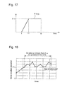
- FIG. 17 is a graph showing an example of a function ⁇ TH (t).
- FIG. 19 shows graphs illustrating problems of the control logic in the related art.
- FIG. 9 is a side view showing the configuration of a wind turbine generator 1 according to the invention.
- the wind turbine generator 1 includes a tower 2 and a nacelle 3 that is provided at the upper end of the tower 2 .
- the nacelle 3 is rotatable in a yaw direction, and is directed to a desired direction by a nacelle rotating mechanism 4 .
- the nacelle 3 is provided with a wound-rotor induction generator 5 and a gear 6 .
- a rotor of the wound-rotor induction generator 5 is coupled with a rotation shaft 7 a of a wind turbine rotor 7 through a gear 6 .
- the wind turbine rotor 7 includes a hub 8 that is connected to the rotation shaft 7 a , and blades 9 that are fixed to the hub 8 .
- the nacelle 3 is further provided with a wind vane/anemometer 10 that measures wind speed and a wind direction.
- FIG. 10 is a cross-sectional view showing an example of the configuration of the nacelle rotating mechanism 4 .
- the nacelle rotating mechanism 4 includes a yaw motor 11 , a decelerator 12 , a pinion 13 , an internal gear 14 , a yaw braking mechanism 15 , and a brake disc 16 .
- the yaw motor 11 , the decelerator 12 , the pinion 13 , and the yaw braking mechanism 15 are mounted on the nacelle 3 , and move together with the nacelle 3 . Meanwhile, the internal gear 14 and the brake disc 16 are fixed to the tower 2 .
- a rotor of the yaw motor 11 is mechanically connected to the pinion 13 through the decelerator 12 , and the pinion 13 and the internal gear 14 are engaged with each other.
- the pinion 13 rotates, so that yaw rotation of the nacelle 3 is performed.
- Yaw rotation of the nacelle 3 is braked by the braking mechanism 15 .
- brake shoes 17 of the yaw braking mechanism 15 clamp the brake disc 16 , yaw rotation of the nacelle 3 is braked or stopped.
- the controller 21 decides a desired direction of the wind turbine rotor 7 from the wind speed and the wind direction that are measured by the wind vane/anemometer 10 , and performs yaw rotation of the nacelle 3 by operating the yaw motor 11 so that the wind turbine rotor 7 is directed to a desired direction. Further, if the wind turbine rotor 7 is directed to a desired direction by the yaw rotation, the controller 21 brakes the yaw rotation by operating the braking mechanism 15 .
- the yaw control according to a first intermediate embodiment which is obtained by modifying the yaw control of the wind turbine generator in the related art having been described with reference to FIG. 18 , will be described below.
- the yaw control is performed in response to the wind direction that is measured by the wind vane/anemometer 10 . More specifically, the controller 21 performs the yaw control as follows:
- the wind vane/anemometer 10 measures a wind direction, which corresponds to each time, at predetermined sampling intervals, and supplies wind direction data, which represent the wind direction corresponding to each time, to the controller 21 .
- the wind direction is defined as an angle that is formed by a predetermined reference direction.
- the controller 21 generates wind direction data for control, which are actually used for yaw control, by performing a low-pass filtering of the measured wind direction data (most simply, by averaging several wind direction data that are temporally adjacent), and calculates the difference between the orientation of the wind turbine and the wind direction, which is represented in the wind direction data for control, as a wind direction deviation.
- the orientation of the wind turbine is represented as an angle that is formed between a predetermined reference direction and the direction of the rotation shaft 7 a of the wind turbine rotor 7 .
- the wind direction deviation is a datum that has one of a positive value, a negative value, or zero.
- the value, which is obtained by subtracting the angle of the orientation of the wind turbine from the wind direction represented in the wind direction data for control is defined as a wind direction deviation in the first intermediate embodiment and embodiments to be described below.
- the controller 21 performs yaw rotation of the nacelle 3 by controlling the motor drive unit 22 and the braking mechanism drive unit 23 in response to the calculated wind direction deviation. If satisfying at least one of the following two conditions in the first intermediate embodiment, the controller 21 performs yaw rotation so that the wind direction deviation becomes zero (that is, in a direction that is indicated by the newest wind direction data for control).
- Condition (1) mainly contributes to yaw control in a situation where the wind direction changes at random so that the degree of turbulence is large and Condition (2) mainly contributes to yaw control in a situation where the wind direction changes gradually over a long time. Since the magnitude of the average wind direction deviation is reduced without increasing the number of yaw rotations as described below, the control logic is effective.
- FIG. 12 is a view that comparing the yaw control, which is performed by a control logic in the related art shown in FIG. 18 , with the yaw control that is performed by a control logic of the first intermediate embodiment.
- FIG. 12( a ) is a graph showing the change of the wind direction deviation that corresponds to the control logic in the related art.
- FIG. 12( a ) shows the change of the wind direction deviation when there is employed a control logic, which performs yaw rotation of the nacelle 3 so that the wind direction deviation becomes zero if the absolute value of the wind direction deviation is not less than 20° for the last 20 seconds.
- FIG. 12( b ) is a graph showing the change in the wind direction deviation that corresponds to the control logic of this embodiment in a situation where the wind direction changes gradually over a long time
- FIG. 12 ( c ) is a graph showing the change in the wind direction deviation that corresponds to the control logic of this embodiment in a situation where the wind direction changes at random so that the degree of turbulence is large.
- the threshold ⁇ TH1 of Condition (1) is set to 20°
- the duration T 1 is set to 20 seconds
- the threshold ⁇ TH2 of Condition (2) is set to 5°
- the duration T 2 is set to 100 seconds.
- yaw rotation is not performed until the absolute value of the wind direction deviation exceeds a threshold of 20° even when the wind direction changes gradually over a long time. Accordingly, the average wind direction deviation is increased.
- the threshold starting the yaw rotation is set low (for example, set to 5°) even in the control logic in the related art, it may be possible to reduce the average wind direction deviation.
- the number of yaw rotations increases in this approach.
- Condition (2) it may be possible to reduce the average wind direction deviation and to suppress an increase of the number of the yaw rotation at the same time. If Condition (2) is satisfied in a situation where the wind direction changes gradually over a long time, the yaw rotation is performed. Since the threshold ⁇ TH2 is set relatively low in Condition (2) (set to 5° in the embodiment of FIG. 12( b )), it may be possible to make the average wind direction deviation small. In addition, since the duration T 2 of Condition (2) is set to be relatively long, an increase in the number of yaw rotations is suppressed.
- Condition (1) if Condition (1) is satisfied in the situation where the wind direction changes at random so that the degree of turbulence is large, yaw rotation is performed. Since the threshold ⁇ TH1 is set to be relatively large in Condition (1), yaw rotation is performed only when being needed actually. Accordingly, it may be possible to suppress an increase in the number of yaw rotations.
- a second intermediate embodiment it is determined which situation of “a situation where the wind direction changes at random so that the degree of turbulence is large” (first situation) and “a situation where the wind direction changes gradually over a long time” (second situation) the current wind situation corresponds to.
- first situation a situation where the wind direction changes at random so that the degree of turbulence is large
- second situation a situation where the wind direction changes gradually over a long time
- the configuration of the wind turbine generator 1 is the same as that of the first intermediate embodiment.
- the controller 21 determines which situation of the two situations the current wind situation corresponds to, by the following control logic from the wind direction data obtained by the wind vane/anemometer 10 .
- the controller 21 consecutively calculates an average wind direction during the latest predetermined time in the past (for example, for the latest one minute in the past). Further, if a period, where a difference between the average wind direction that has been calculated latest and the average wind direction that is calculated just before the calculation of the average wind direction is within a predetermined angle, continues for a predetermined time, the controller 21 determines that the current wind situation is the second situation where the wind direction changes gradually over a long time.
- the controller 21 determines that the current wind situation is the first situation where the wind direction changes at random so that the degree of turbulence is large. As shown in FIG. 13 , it may be possible to determine two situations with some accuracy by using the control logic.
- control logic determining that the wind situation is “a situation where the wind direction changes at random so that the degree of turbulence is large” in a specific period of one day (or of one year) and determining that the wind situation is “a situation where the wind direction changes gradually over a long time” in other specific periods. From data observed in the past, it may be possible to appropriately decide a period where the wind situation is considered as “a situation where the wind direction changes at random so that the degree of turbulence is large” and a period where the wind situation is considered as “a situation where the wind direction changes gradually over a long time”. According to this control logic, it may be possible to easily determine which situation of the above-mentioned situations the current wind situation corresponds to.
- the controller 21 performs yaw rotation so that the wind direction deviation becomes zero when a state where the absolute value of the wind direction deviation is not less than a predetermined threshold ⁇ TH1 (or exceeds a threshold ⁇ TH1 ) continues for a predetermined duration T 1 seconds (for example, for 20 seconds).
- the controller 21 performs yaw rotation so that the sign of the wind direction deviation becomes opposite before and after the yaw rotation when a state where the absolute value of the wind direction deviation is not less than a predetermined threshold ⁇ TH2 (or exceeds a threshold ⁇ TH2 ) continues for a predetermined duration T 2 seconds (for example, for 20 seconds), and the absolute value of the wind direction deviation after the yaw rotation becomes equal to the threshold ⁇ TH2 .
- the threshold ⁇ TH2 is set to 10°
- a state where the wind direction deviation exceeds to +10° continues for a predetermined duration T (for example, 20 seconds)
- yaw rotation is performed so that the wind direction deviation becomes ⁇ 10°.
- FIG. 14( a ) is a graph showing a relationship between a wind direction and the orientation of a wind turbine when yaw control is performed by the control logic of the second intermediate embodiment in a situation where the wind direction changes gradually over a long time. It is assumed that the change in the wind direction is constant in the graph of FIG. 14( a ). As understood from FIG. 14( a ), even when the change in the wind direction is constant, the wind direction deviation (that is, a difference between a wind direction and the orientation of a wind turbine) alternately has a positive value and a negative value in the control logic of this embodiment. Accordingly, an average of the wind direction deviation approaches zero.
- a threshold ⁇ TH2 used in a situation where the wind direction changes gradually over a long time is set to be small in the control logic of this embodiment, the number of yaw rotations is not increased so much.
- the reason for this is that the deviation ⁇ (t) of the wind direction is changed in a range including “ ⁇ TH2 ⁇ (t) ⁇ + ⁇ TH2 ” (not between zero and + ⁇ TH2 or between zero and ⁇ TH2 ) in a situation where the wind direction changes gradually over a long time in this embodiment. If the threshold ⁇ TH2 is set low, the average of the wind direction deviation approaches zero. Accordingly, the setting of the small threshold is effective.
- FIG. 14( b ) shows that the wind direction deviation is always negative.
- FIG. 15 is a graph showing the superiority of the control logic of the second intermediate embodiment to the control logic in the related art more clearly.
- FIG. 15 shows the efficiency of the wind turbine generator 1 when the rate of change in the wind direction is constant and the width of change of the wind direction deviation of the control logic of this intermediate embodiment is equal to that of the control logic in the related art. It should be noted that conditions that the rate of change in the wind direction is constant and the width of change of the wind direction deviation of the control logic of this intermediate embodiment is equal to that of the control logic in the related art are decided from the fact that the number of yaw rotations of the control logic of this intermediate embodiment is equal to that of the control logic in the related art. More specifically, FIG.
- a threshold ⁇ TH2 is set to 10° in the control logic of this intermediate embodiment and a threshold ⁇ TH starting the yaw rotation is set to 20° in the control logic in the related art. Since the width of change of the wind direction deviation is the same even in any case, the number of yaw rotations is also the same.
- the wind direction deviation is changed in the range of ⁇ 20° to zero in the control logic in the related art, but the wind direction deviation is changed in the range of ⁇ 10° to +10° in the control logic of this intermediate embodiment.
- the efficiency of the wind turbine generator 1 rapidly decreases. Accordingly, in the control logic in the related art, the efficiency of the wind turbine generator 1 decreases when the wind direction deviation is particularly in the range of ⁇ 20° to ⁇ 10°. Meanwhile, in the control logic of this intermediate embodiment, the decrease in the efficiency of the wind turbine generator 1 is small when the wind direction deviation is in the range of ⁇ 10° to +10°.
- a threshold ⁇ TH starting the yaw rotation is set to be small (for example, set to 10°) even in the control logic in the related art, an average of the magnitude of the wind direction deviation decreases.
- the threshold ⁇ TH is set to be small, the number of yaw rotations increases.
- the suppression of an increase in the number of yaw rotations may be incompatible with the reduction of the average of the absolute value of the wind direction deviation.
- the wind turbine generator 1 of the second intermediate embodiment is in a situation where the wind direction changes gradually over a long time as described above, yaw rotation is performed so that the sign of the wind direction deviation becomes opposite before and after the yaw rotation and the absolute value of the wind direction deviation after the yaw rotation becomes equal to the threshold ⁇ TH2 . Accordingly, it may be possible to reduce the average of the absolute value of the wind direction deviation while suppressing an increase in the number of yaw rotations.
- yaw rotation may be performed so that the absolute value of the wind direction deviation after the yaw rotation becomes a value between the threshold ⁇ TH2 and zero. For example, if a state where the wind direction deviation exceeds +7.5° continues for a predetermined duration (for example, 20 seconds) when the threshold ⁇ TH2 is 7.5°, yaw rotation may be performed so that the wind direction deviation becomes ⁇ 4°. However, in order to reduce the average of the absolute value of the wind direction deviation, it is preferable to perform yaw rotation so that the absolute value of the wind direction deviation after the yaw rotation becomes equal to the threshold ⁇ TH2 .
- the combination of the yaw control of the first intermediate embodiment and the yaw control of the second intermediate embodiment may be performed. More specifically, if Condition (2) of the yaw control of the first intermediate embodiment is satisfied, yaw rotation is performed so that the sign of the wind direction deviation becomes opposite before and after the yaw rotation and the absolute value of the wind direction deviation after the yaw rotation becomes equal to the threshold ⁇ TH2 (the absolute value of the wind direction deviation after the yaw rotation becomes a value between the threshold ⁇ TH2 and zero). If Condition (1) is satisfied, yaw rotation is performed so that the wind direction deviation becomes zero.
- Condition (2) of the first intermediate embodiment corresponds to a case where the wind situation is “a situation where the wind direction changes gradually over a long time”. For this reason, if Condition (2) is satisfied, it is preferable that yaw rotation is performed so that the sign of the wind direction deviation becomes opposite before and after the yaw rotation and the absolute value of the wind direction deviation after the yaw rotation becomes equal to the threshold ⁇ TH2 .
- the average wind direction deviation is further reduced by the second intermediate embodiment in this way, so that the efficiency of the wind turbine generator 1 is improved.
- FIG. 16( a ) is a graph showing the problem of the control logic in the related art shown in FIG. 18 .
- the change of the wind direction deviation is ignored unless the wind direction deviation exceeds a threshold. Accordingly, it may not be possible to detect the transitional change of the wind direction deviation. For this reason, time, which has passed until yaw rotation is actually performed after the wind direction starts to be changed, is lengthened in the control logic in the related art as shown in FIG. 16( a ).
- a state where the wind direction deviation is large, that is, a state where the efficiency of the wind turbine generator 1 deteriorates continues for a long time.
- a control logic that performs yaw rotation at an accurate timing by detecting transitional changes in the wind direction. More specifically, in the third intermediate embodiment, there is employed a control logic for performing yaw rotation so that the wind direction deviation becomes zero if the following conditions are satisfied about all of time t satisfying “t 0 ⁇ T ⁇ t ⁇ t 0 ” assuming that the current time is denoted by t 0 .
- denotes the absolute value of the wind direction deviation at a time t
- T denotes a predetermined value
- ⁇ TH (t) denotes a threshold that is used for the determination of the start of the yaw rotation and is a function that broadly uniformly increases in the range of “t 0 ⁇ T ⁇ t ⁇ t 0 ”.
- the threshold is increased with time.
- T corresponds to the length of a period that is used for the determination of the yaw rotation.
- “broadly” means that a range having constant ⁇ TH (t) may exist in the range of “t 0 ⁇ T ⁇ t ⁇ t 0 ”. However, ⁇ TH (t) should not be set to be constant in the entire range of “t 0 ⁇ T ⁇ t ⁇ t 0 ”.
- this control logic it may be possible to perform yaw rotation at a timing as early as possible by detecting transitional changes in the wind direction.
- a threshold ⁇ TH starting the yaw rotation is increased with time in the control logic of the third intermediate embodiment, it may be possible to consider the change of the wind direction deviation in an initial period where the absolute value of the wind direction deviation is still small, in the determination of the start of the yaw rotation. Accordingly, according to the control logic of the intermediate embodiment, it may be possible to perform yaw rotation at an accurate timing by detecting transitional changes in the wind direction. This is effective in improving the efficiency of the wind turbine generator 1 .
- the function ⁇ TH (t) is set as follows:
- ⁇ TH ⁇ ( t ) ⁇ TH ⁇ 1 - ( t - t 0 ) 2 T 2
- ⁇ TH denotes a predetermined constant.
- the shape of a graph of a function ⁇ TH (t) is similar to a part of a circle or an ellipse as shown in FIG. 16( b ).
- the function ⁇ TH (t) defined by Formula (2) is a function (narrowly) uniformly increasing in the entire range of “t 0 ⁇ T ⁇ t ⁇ t 0 ” and a derived function d ⁇ TH (t)/dt thereof is also a function (narrowly) uniformly decreasing in the entire range of “t 0 ⁇ T ⁇ t ⁇ t 0 ”.
- ⁇ TH (t) defined by Formula (2) is a function broadly uniformly increasing in the entire range of “t 0 ⁇ T ⁇ t ⁇ t 0 ” and a derived function d ⁇ TH (t)/dt thereof is also a function broadly uniformly decreasing in the entire range of “t 0 ⁇ T ⁇ t ⁇ t 0 ”.
- the third intermediate embodiment it may be possible to cope with transitional changes in the wind direction by the third intermediate embodiment.
- the third intermediate embodiment needs to be improved so as to also cope with “a situation where the wind direction changes gradually over a long time”.
- Example 1 uses a technique obtained by improving the stop condition of the yaw rotation, which has been the task of the above-mentioned first to third intermediate embodiments.
- the configuration of the wind turbine generator 1 is the same as those of the first to third intermediate embodiments.
- FIG. 1 is a flowchart illustrating a procedure of yaw rotation control that is performed by a controller 21 of Example 1. The yaw rotation control of Example 1 will be described with reference to FIG. 1 .
- Step S 1 yaw rotation starts.
- Step S 1 The specific condition of Step S 1 will be described.
- a wind vane/anemometer 10 measures a wind direction, which corresponds to each time, at predetermined sampling intervals, and supplies wind direction data, which represent the wind direction corresponding to each time, to a controller 21 .
- the wind direction is defined as an angle that is formed by a predetermined reference direction.
- the controller 21 performs the yaw rotation of a nacelle 3 by controlling a motor drive unit 22 and a braking mechanism drive unit 23 in response to the calculated wind direction deviation. If satisfying at least one of the following two conditions in Example 1, the controller 21 performs yaw rotation so that the wind direction deviation becomes zero (that is, in a direction that is indicated by the newest wind direction data for control).
- a threshold ⁇ TH1 for example, 5°
- ⁇ TH1 for example, 5°
- Step S 1 The start condition of yaw rotation in Step S 1 is the same as that of the yaw rotation in the above-mentioned first intermediate embodiment.
- Step S 1 stopping the yaw rotation is determined by a stop logic shown in FIG. 1 by a broken line.
- Step S 2 the stop logic, first, the yaw rotation continues for a predetermined time ⁇ t in Step S 2 .
- Step S 3 an average of the wind direction is calculated in Step S 3 .
- the average of the wind direction is an average of the wind direction in the range of the time t 0 ⁇ T to the time t 0 .
- the wind vane/anemometer 10 measures a wind direction, which corresponds to each time, at predetermined sampling intervals, and the controller 21 calculates an average of the wind direction by using wind direction data that are supplied to the controller 21 and represent the wind direction corresponding to each time.
- Step S 4 If the average of the wind direction is calculated in Step S 3 , it is determined in Step S 4 whether the orientation of the wind turbine (the direction of the wind turbine rotor 7 ) reaches the average of the wind direction.
- Step S 4 If it is determined in Step S 4 that the orientation of the wind turbine does not reach the average of the wind direction, Steps S 2 to S 4 are repeated until the orientation of the wind turbine reaches the average of the wind direction.
- Step S 4 If it is determined in Step S 4 that the orientation of the wind turbine reaches the average of the wind direction, the yaw rotation is stopped in Step S 5 .
- FIG. 2 is a view comparing the yaw control, which is performed by control logics in the related art and of the first and third intermediate embodiments during the stopping of yaw rotation, with the yaw control that is performed by a control logic of Example 1.
- FIG. 2( a ) is a graph showing the changes in the wind direction and the orientation of the wind turbine that are caused by the control logics in the related art and of intermediate embodiments.
- FIG. 2( a ) shows an average of the wind direction and the change of the orientation of the wind turbine when there is employed a control logic, which performs yaw rotation of the nacelle 3 so that the wind direction deviation becomes zero if the absolute value of the wind direction deviation is not less than 20° for the last 20 seconds.
- FIG. 2( b ) is a graph showing the changes in the wind direction and the orientation of the wind turbine that are caused by a control logic of Example 1. Specifically, FIG. 2( b ) shows an average of the wind direction and the change of the orientation of the wind turbine when there is employed a control logic, which performs yaw rotation of the nacelle 3 so that the difference between the average of the wind direction and the orientation of the wind turbine becomes zero if the absolute value of the wind direction deviation is not less than 20° for the last 20 seconds.
- control is performed so that the yaw rotation is stopped when the difference between the average of the wind direction and the orientation of the wind turbine becomes zero. Accordingly, even though the wind direction and the orientation of the wind turbine momentarily correspond to each other due to a momentary change in the wind direction, it may be possible to stop the yaw rotation at an appropriate position without the stop of the yaw rotation.
- FIG. 2 has shown an example where yaw rotation starts in Condition (2), that is, if the absolute value of the wind direction deviation is not less than 20° for the last 20 seconds. However, even though yaw rotation starts in Condition (1), the control of stopping the yaw rotation is the same.
- Example 2 uses a technique obtained by improving the stop condition of the yaw rotation, which has been the task of the above-mentioned first to third intermediate embodiments.
- the configuration of the wind turbine generator 1 is the same as that of Example 1.
- FIG. 3 is a flowchart illustrating a procedure of yaw rotation control that is performed by a controller 21 of Example 2. The yaw rotation control of Example 2 will be described with reference to FIG. 3 .
- Step S 11 yaw rotation starts.
- Step S 11 Since the specific condition of Step S 11 is the same as that of Step S 1 of Example 1, the description of the specific condition of Step S 11 will be omitted.
- Step S 11 stopping the yaw rotation is determined by a stop logic shown in FIG. 3 by a broken line.
- Step S 12 the yaw rotation continues for a predetermined time ⁇ t in Step S 12 .
- Step S 13 it is determined in Step S 13 whether the orientation of the wind turbine (the direction of the wind turbine rotor 7 ) reaches the wind direction.
- Step S 13 If it is determined in Step S 13 that the orientation of the wind turbine reaches the wind direction, it is determined in Step S 14 whether an angle of yaw rotation reaches the rotation threshold.
- the rotation threshold means ⁇ TH1 and ⁇ TH2 of Conditions (1) and (2).
- the rotation threshold in Step S 4 is determined using ⁇ TH1 when Condition (1) is satisfied and the yaw rotation thus starts, and the rotation threshold in Step S 4 is determined using ⁇ TH2 when Condition (2) is satisfied and the yaw rotation thus starts.
- Step S 14 If it is determined in Step S 14 that an angle of yaw rotation does not reach the rotation threshold, Steps S 12 to S 14 are repeated until it is determined in Step S 14 that the angle of yaw rotation reaches the rotation threshold.
- Step S 14 If it is determined in Step S 14 that an angle of yaw rotation reaches the rotation threshold, the yaw rotation is stopped in Step S 15 .
- FIG. 4 is a view comparing the yaw control, which is performed by control logics in the related art and of the first and third intermediate embodiments during the stopping of yaw rotation, with the yaw control that is performed by a control logic of Example 2.
- FIG. 4( a ) is a graph showing the changes in the wind direction and the orientation of the wind turbine that are caused by the control logics in the related art and of intermediate embodiments.
- FIG. 4( a ) shows the changes in the wind direction and the orientation of the wind turbine when there is employed a control logic, which performs yaw rotation of the nacelle 3 so that the wind direction deviation becomes zero if the absolute value of the wind direction deviation is not less than 20° for the last 20 seconds.
- FIGS. 4( b ) and 4 ( c ) are graphs showing the changes in the wind direction and the orientation of the wind turbine that are caused by a control logic of Example 2. Specifically, FIG. 4( b ) shows the changes in the wind direction and the orientation of the wind turbine when yaw rotation starts if the absolute value of the wind direction deviation is not less than 20° for the last 20 seconds, the orientation of the wind turbine reverses the wind direction at the time of the yaw rotation of 20°, and the yaw rotation is stopped at the time of the yaw rotation of 20°.
- FIG. 4( b ) shows the changes in the wind direction and the orientation of the wind turbine when yaw rotation starts if the absolute value of the wind direction deviation is not less than 20° for the last 20 seconds, the orientation of the wind turbine reverses the wind direction at the time of the yaw rotation of 20°, and the yaw rotation is stopped at the time of the yaw rotation of 20°.
- 4( c ) shows the changes in the wind direction and the orientation of the wind turbine when yaw rotation starts if the absolute value of the wind direction deviation is not less than 20° for the last 20 seconds, the yaw rotation continues as it is since the orientation of the wind turbine does not reverse the wind direction at the time of the yaw rotation of 20°, and the yaw rotation is performed if the difference between the wind direction and the orientation of the wind turbine becomes zero.
- Example 2 in the control logic of Example 2 that is shown in FIGS. 4( b ) and 4 ( c ), in order to perform the yaw rotation by an angle corresponding to at least the rotation threshold, even though the wind direction changes momentarily before the yaw rotation reaches the rotation threshold and the wind direction and the orientation of the wind turbine momentarily correspond to each other, it may be possible to stop the yaw rotation at an appropriate position without the stop of the yaw rotation.
- Example 2 if being applied to “a situation where the wind direction changes gradually over a long time”, and the control of Example 2 is effective.
- Example 3 yaw rotation is stopped at a further appropriate position by the combination of techniques described in Examples 1 and 2.
- the configuration of the wind turbine generator 1 is the same as those of Examples 1 and 2.
- FIG. 5 is a flowchart illustrating a procedure of yaw rotation control that is performed by a controller 21 of Example 3. The yaw rotation control of Example 3 will be described with reference to FIG. 5 .
- Step S 21 yaw rotation starts.
- Step S 21 Since the specific condition of Step S 21 is the same as that of Step S 1 of Example 1, the description of the specific condition of Step S 11 will be omitted.
- Step S 21 stopping the yaw rotation is determined by a stop logic shown in FIG. 3 by a broken line.
- Step S 22 the yaw rotation continues for a predetermined time ⁇ t in Step S 22 .
- Step S 23 an average of the wind direction is calculated in Step S 23 . Since an average of the wind direction has been described in Example 1, the description of an average of the wind direction will be omitted here.
- Step S 24 If an average of the wind direction is calculated in Step S 23 , it is determined in Step S 24 whether the orientation of the wind turbine (the direction of the wind turbine rotor 7 ) reaches the average of the wind direction.
- Step S 24 If it is determined in Step S 24 that the orientation of the wind turbine does not reach the average of the wind direction, Steps S 22 to S 24 are repeated until the orientation of the wind turbine reaches the average of the wind direction.
- Step S 24 If it is determined in Step S 24 that the orientation of the wind turbine reaches the average of the wind direction, it is determined in Step S 25 whether an angle of yaw rotation reaches the rotation threshold.
- Step 25 If it is determined in Step 25 that an angle of yaw rotation reaches the rotation threshold, the yaw rotation is stopped in Step S 26 .
- FIG. 6 is a view comparing the yaw control, which is performed by control logics in the related art and of the first and third intermediate embodiments during the stopping of yaw rotation, with the yaw control that is performed by a control logic of Example 3.
- FIG. 6( a ) is a graph showing the changes in the wind direction and the orientation of the wind turbine that are caused by the control logics in the related art and of intermediate embodiments.
- FIG. 6( a ) shows the changes in the wind direction and the orientation of the wind turbine when there is employed a control logic, which performs yaw rotation of the nacelle 3 so that the wind direction deviation becomes zero if the absolute value of the wind direction deviation is not less than 20° for the last 20 seconds.
- FIGS. 6( b ) and 6 ( c ) are graphs showing the changes in the wind direction and the orientation of the wind turbine that are caused by a control logic of Example 3. Specifically, FIG. 6( b ) shows the changes of an average of the wind direction and the orientation of the wind turbine when yaw rotation starts if the absolute value of the wind direction deviation is not less than 20° for the last 20 seconds, the orientation of the wind turbine reverses an average of the wind direction at the time of the yaw rotation of 20°, and the yaw rotation is stopped at the time of the yaw rotation of 20°.
- FIG. 6( b ) shows the changes of an average of the wind direction and the orientation of the wind turbine when yaw rotation starts if the absolute value of the wind direction deviation is not less than 20° for the last 20 seconds, the orientation of the wind turbine reverses an average of the wind direction at the time of the yaw rotation of 20°, and the yaw rotation is stopped at the time of the yaw
- 6( c ) shows the changes of an average of the wind direction and the orientation of the wind turbine when yaw rotation starts if the absolute value of the wind direction deviation is not less than 20° for the last 20 seconds, the yaw rotation continues as it is since the orientation of the wind turbine does not reverse an average of the wind direction at the time of the yaw rotation of 20°, and the yaw rotation is performed if the difference between the average of the wind direction and the orientation of the wind turbine becomes zero.
- Example 2 in order to perform the yaw rotation by an angle corresponding to at least the rotation threshold, the wind direction is momentarily changed before the yaw rotation reaches the rotation threshold. Accordingly, even though the wind direction and the orientation of the wind turbine momentarily correspond to each other, the yaw rotation is not stopped. Further, the average of the wind direction is used. Accordingly, even though the wind direction is momentarily changed and the wind direction and the orientation of the wind turbine momentarily correspond to each other when the yaw rotation continues so as to exceed the rotation threshold if the yaw rotation continues above the rotation threshold as shown in FIG. 6( c ), it may be possible to stop the yaw rotation at an appropriate position without the stop of the yaw rotation.
- Example 3 if being applied to “a situation where the wind direction changes gradually over a long time”, and the control of Example 3 is effective.
- Example 1 is always effective in improving performance and reducing the frequency of the yaw rotation
- the control of Examples 2 and 3 is particularly effective in “a situation where the wind direction changes gradually over a long time”.
- control logic which has been described in the second intermediate embodiment, for determining which situation of “a situation where the wind direction changes at random so that the degree of turbulence is large” (first situation) and “a situation where the wind direction changes gradually over a long time” (second situation) the current wind situation corresponds to.
- the yaw rotation is stopped by the control disclosed in Example 1 when the current wind situation is the first situation and the yaw rotation is stopped by the control disclosed in Example 2 or 3 when the current wind situation is the second situation, it is further effective in improving performance and reducing the frequency of the yaw rotation.
- Example 4 uses a technique obtained by improving the start condition of the yaw rotation, which has been the tasks of the above-mentioned first to third intermediate embodiments, in order to cope with transitional changes in the wind direction.
- the configuration of the wind turbine generator 1 is the same as those of the first to third intermediate embodiments.
- FIG. 7( a ) is a graph showing control logics used in Examples 1 to 3
- FIGS. 7( b ) and 7 ( c ) are graphs showing a control logic of Example 4.
- a control logic which performs yaw rotation at an accurate timing by detecting transitional changes in the wind direction, is employed in Example 4.
- the current wind situation is determined by the control logic, which has been described in the second intermediate embodiment, for determining which situation of “a situation where the wind direction changes at random so that the degree of turbulence is large” (first situation) and “a situation where the wind direction changes gradually over a long time” (second situation) the current wind situation corresponds to.
- the yaw rotation of the nacelle is performed when the wind direction deviation satisfies a predetermined condition about all of time t satisfying “t s ⁇ t ⁇ t 0 ”.
- the predetermined condition is
- denotes the absolute value of the wind direction deviation at each time t
- ⁇ TH1 (t) denotes a function that broadly uniformly increases in the range of “t 0 ⁇ T 1 ⁇ t ⁇ t 0 ”
- a derived function d ⁇ TH1 (t)/dt of ⁇ TH1 (t) with respect to time broadly uniformly decreases in the range of “t 0 ⁇ T 1 ⁇ t ⁇ t 0 ” except for time t where a derived function cannot be defined.
- ⁇ TH2 (t) denotes a function that broadly uniformly increases in the range of “t 0 ⁇ T 1 ⁇ t ⁇ t 0 ”, and a derived function d ⁇ TH2 (t)/dt of ⁇ TH2 (t) with respect to time broadly uniformly increases in the range of “t 0 ⁇ T 1 ⁇ t ⁇ t 0 ” except for time t where a derived function cannot be defined.
- t b in FIG. 7 corresponds to t 0 ⁇ T 1 .
- a curve connecting a point A with a point B and a straight line where the wind direction deviation is constant between the point A and time t 0 correspond to ⁇ TH1 (t s ).
- a curve connecting a point A with a point B and a straight line where the wind direction deviation is constant between the point A and time t 0 correspond to ⁇ TH2 (t s ).
- Example 5 the number of yaw rotation, which is performed between the current time and a predetermined time, is measured and the rotation condition is changed in accordance with the measured number of the yaw rotation. Specifically, if the number of rotations for a predetermined time (for example, one hour) in the past is smaller than a predetermined number of rotations (for example, three times) at the time of the start of the yaw rotation or if time elapsed from the previous yaw rotation is longer than a predetermined time (for example, 20 minutes) at the time of the start of the yaw rotation, the rotation condition is eased.
- a predetermined time for example, one hour
- a predetermined number of rotations for example, three times
- the rotation condition is tightened.
- the easing of the rotation condition means the decrease of a time threshold or the decrease of an angle threshold in the condition of the rotation start
- the tightening of the rotation condition means the increase of the time threshold or the increase of the angle threshold
- FIG. 8 is a flowchart illustrating a procedure of yaw rotation control of Examples 1 to 5 of the invention.
- yaw rotation starts in Step S 51 by a rotation condition X.
- the rotation condition X is a condition for the start of the yaw rotation, and the conditions described in the first to third intermediate embodiments or the conditions described in Example 4 may be used as the rotation condition.
- Step S 51 stopping the yaw rotation is determined in Step S 52 by a rotation stop logic and the yaw rotation is stopped in Step S 53 .
- Any one of the rotation stop logics of Examples 1, 2, and 3 described with reference to FIGS. 1 , 3 , and 5 may be used as the rotation stop logic in Step S 52 .
- Step S 55 it is determined in Step S 55 whether time elapsed from the stop time of the previous yaw rotation to the start of the current yaw rotation is not less than a predetermined time M. Meanwhile, the predetermined time M is set for each rotation condition.
- Step S 55 If it is determined in Step S 55 that the elapsed time is not less than a predetermined time, the procedure proceeds to Step S 56 and the angle threshold or the time threshold of the rotation condition X is decreased, that is, the rotation condition is eased.
- Step S 55 If it is determined in Step S 55 that the elapsed time is less than a predetermined time, the procedure proceeds to Step S 57 and the angle threshold or the time threshold of the rotation condition X is increased, that is, the rotation condition is tightened.
- Step S 53 If the yaw rotation is stopped in Step S 53 and the rotation condition is eased or made tight in Step S 56 or S 57 , the start of the rotation is determined in Step S 54 while the eased or tightened rotation condition X′ is used as a new rotation condition X. If the condition of the rotation start is satisfied, the procedure returns to Step S 51 and the yaw rotation starts again.
- the invention may be used as a yaw control technique for a wind turbine generator that can suppress an increase in the number of yaw rotations and decrease magnitude of the wind direction deviation even though the wind direction changes gradually over a long time, and a yaw control technique that improves the efficiency of the wind turbine generator by performing yaw rotation at an appropriate timing through the early detection of transitional changes in the wind direction.
Landscapes
- Engineering & Computer Science (AREA)
- Life Sciences & Earth Sciences (AREA)
- Sustainable Development (AREA)
- Sustainable Energy (AREA)
- Chemical & Material Sciences (AREA)
- Combustion & Propulsion (AREA)
- Mechanical Engineering (AREA)
- General Engineering & Computer Science (AREA)
- Wind Motors (AREA)
Abstract
Description
|Δθ(t)|≧θTH(t) (1a)
or
|Δθ(t)|>θTH(t) (1b)
θTH(t)=θTH(T 1 ≦t≦t 0) (3a)
θTH(t)=a(t−T 1)+θTH(T≦t≦T 1) (3b)
Claims (13)
Applications Claiming Priority (3)
| Application Number | Priority Date | Filing Date | Title |
|---|---|---|---|
| JP2008-278643 | 2008-10-29 | ||
| JP2008278643A JP5199828B2 (en) | 2008-10-29 | 2008-10-29 | Wind power generator and control method thereof |
| PCT/JP2009/058790 WO2010050260A1 (en) | 2008-10-29 | 2009-04-30 | Wind power generator, and control method therefor |
Publications (2)
| Publication Number | Publication Date |
|---|---|
| US20110127772A1 US20110127772A1 (en) | 2011-06-02 |
| US8450867B2 true US8450867B2 (en) | 2013-05-28 |
Family
ID=42128630
Family Applications (1)
| Application Number | Title | Priority Date | Filing Date |
|---|---|---|---|
| US12/674,211 Active 2030-11-29 US8450867B2 (en) | 2008-10-29 | 2009-04-30 | Wind turbine generator and its control method |
Country Status (10)
| Country | Link |
|---|---|
| US (1) | US8450867B2 (en) |
| EP (1) | EP2314869B1 (en) |
| JP (1) | JP5199828B2 (en) |
| KR (1) | KR101204216B1 (en) |
| CN (1) | CN101978161B (en) |
| AU (1) | AU2009308570B2 (en) |
| BR (1) | BRPI0909020A2 (en) |
| CA (1) | CA2716155A1 (en) |
| TW (1) | TWI394891B (en) |
| WO (1) | WO2010050260A1 (en) |
Cited By (7)
| Publication number | Priority date | Publication date | Assignee | Title |
|---|---|---|---|---|
| US9587629B2 (en) | 2014-06-30 | 2017-03-07 | General Electric Company | Methods and systems to operate a wind turbine system using a non-linear damping model |
| US10100812B2 (en) | 2014-06-30 | 2018-10-16 | General Electric Company | Methods and systems to operate a wind turbine system |
| US10539116B2 (en) | 2016-07-13 | 2020-01-21 | General Electric Company | Systems and methods to correct induction for LIDAR-assisted wind turbine control |
| US11365716B2 (en) * | 2018-03-01 | 2022-06-21 | Beijing Goldwind Science & Creation Windpower Equipment Co., Ltd. | Control method and device for avoiding run-away and wind turbine |
| US11378057B2 (en) * | 2018-02-22 | 2022-07-05 | Siemens Gamesa Renewable Energy A/S | Method for controlling yawing of a wind turbine |
| US20220213872A1 (en) * | 2019-04-01 | 2022-07-07 | Ntn Corporation | Condition monitoring system and wind power generation system including the same |
| US11674498B1 (en) | 2022-04-21 | 2023-06-13 | General Electric Renovables Espana, S.L. | Systems and methods for controlling a wind turbine |
Families Citing this family (20)
| Publication number | Priority date | Publication date | Assignee | Title |
|---|---|---|---|---|
| CN101886611B (en) * | 2010-06-13 | 2011-12-07 | 曹峻岭 | Automatic directing controller of wind driven generator |
| CA2821572C (en) | 2010-12-30 | 2014-12-02 | General Electric Company | System, device, and method for adjusting wind turbine component workload |
| TWI482041B (en) * | 2011-04-08 | 2015-04-21 | Ind Tech Res Inst | Method and apparatus for evaluating efficiency of wind generator |
| CN103857904B (en) * | 2011-05-06 | 2017-06-13 | 康道尔风能有限公司 | System for making to be minimized by the torque needed for control power of going off course in the wind turbine that two vane type bands wave hinge |
| DK177292B1 (en) * | 2011-06-30 | 2012-10-08 | Envision Energy Denmark Aps | A wind turbine and an associated yaw control method |
| WO2013075720A2 (en) * | 2011-11-21 | 2013-05-30 | Vestas Wind Systems A/S | A shutdown controller for a wind turbine and a method of shutting down a wind turbine |
| KR101368754B1 (en) * | 2013-01-11 | 2014-03-05 | 삼성중공업 주식회사 | Output controlling method and device of wind power generating system using angle of attack |
| EP3201465B1 (en) | 2014-09-29 | 2018-11-07 | Vestas Wind Systems A/S | Verification of wind turbine nacelle yaw position sensor and yaw control system |
| JP6363123B2 (en) | 2016-02-29 | 2018-07-25 | 三菱重工業株式会社 | Windmill, yaw control device and operation control method thereof |
| WO2018219416A1 (en) | 2017-05-31 | 2018-12-06 | Vestas Wind Systems A/S | Wind turbine yaw control system with improved wind direction tracking |
| JP6475292B2 (en) * | 2017-07-28 | 2019-02-27 | 株式会社日立製作所 | Wind power generator, control method thereof and repair method |
| JP2019143583A (en) | 2018-02-23 | 2019-08-29 | 株式会社日立製作所 | Wind power generator and control method thereof |
| CN108798997B (en) * | 2018-06-28 | 2020-02-07 | 北京金风科创风电设备有限公司 | Control method, device, controller and system of wind generating set |
| EP3620649A1 (en) * | 2018-09-10 | 2020-03-11 | Siemens Gamesa Renewable Energy A/S | Controlling wind turbines in presence of wake implications |
| JP7236374B2 (en) * | 2019-12-05 | 2023-03-09 | 株式会社日立製作所 | wind turbine |
| CN113027680B (en) * | 2019-12-25 | 2024-02-06 | 金风科技股份有限公司 | Yaw opposite wind control method and device of wind generating set |
| JP7455722B2 (en) | 2020-10-15 | 2024-03-26 | 株式会社日立製作所 | Wind power generator and its control method |
| CN114000975B (en) * | 2021-11-03 | 2023-08-18 | 华能通辽风力发电有限公司 | Yaw system of wind turbine generator |
| CN114718811B (en) * | 2022-06-09 | 2022-09-16 | 东方电气风电股份有限公司 | Self-adaptive control method for monitoring fan blade state based on GPS |
| CN116971917B (en) * | 2023-06-28 | 2024-01-30 | 北京金风科创风电设备有限公司 | Yaw control method, device, controller and wind turbine generator |
Citations (11)
| Publication number | Priority date | Publication date | Assignee | Title |
|---|---|---|---|---|
| JP2002530590A (en) | 1998-11-26 | 2002-09-17 | アロイス・ヴォベン | Wind direction tracking drive for wind power generation equipment |
| KR20030071855A (en) | 2001-02-10 | 2003-09-06 | 우벤 알로이즈 | Azimuth guidance for a wind energy plant |
| KR20040011528A (en) | 2001-06-07 | 2004-02-05 | 우벤 알로이즈 | Method for maximizing the energy output of a wind turbine |
| JP2004285858A (en) | 2003-03-19 | 2004-10-14 | Mitsubishi Electric Corp | Wind power generation system and control method for wind power generator |
| JP2005113899A (en) | 2003-09-19 | 2005-04-28 | Nabtesco Corp | Yaw drive method and device for wind power generator |
| US6946751B2 (en) * | 2003-03-19 | 2005-09-20 | Mitsubishi Denki Kabushiki Kaisha | Wind power generation system |
| WO2005090781A1 (en) | 2004-03-22 | 2005-09-29 | Sway As | A method for reduction of axial power variations of a wind power plant |
| WO2005108784A1 (en) | 2004-05-07 | 2005-11-17 | Mitsubishi Denki Kabushiki Kaisha | Wind power generation evaluation system and prediction control service system for wind power generator |
| CN101117945A (en) | 2007-09-11 | 2008-02-06 | 天津大学 | Wind turbine yaw device |
| CN101122279A (en) | 2006-08-10 | 2008-02-13 | 郭峰 | Wind-driven generator synchronous belt transmission automatic wind-aiming drift device |
| WO2008126659A1 (en) | 2007-04-10 | 2008-10-23 | Mitsubishi Heavy Industries, Ltd. | Wind turbine generator and its control method |
Family Cites Families (2)
| Publication number | Priority date | Publication date | Assignee | Title |
|---|---|---|---|---|
| US4565929A (en) * | 1983-09-29 | 1986-01-21 | The Boeing Company | Wind powered system for generating electricity |
| CA2522280A1 (en) * | 2003-04-17 | 2004-10-28 | New World Generation Inc. | Wind turbine with friction drive power take off on outer rim |
-
2008
- 2008-10-29 JP JP2008278643A patent/JP5199828B2/en active Active
-
2009
- 2009-04-30 BR BRPI0909020A patent/BRPI0909020A2/en not_active IP Right Cessation
- 2009-04-30 KR KR1020107020741A patent/KR101204216B1/en not_active Expired - Fee Related
- 2009-04-30 CN CN2009801095839A patent/CN101978161B/en active Active
- 2009-04-30 EP EP09823373.7A patent/EP2314869B1/en active Active
- 2009-04-30 US US12/674,211 patent/US8450867B2/en active Active
- 2009-04-30 WO PCT/JP2009/058790 patent/WO2010050260A1/en not_active Ceased
- 2009-04-30 CA CA2716155A patent/CA2716155A1/en not_active Abandoned
- 2009-04-30 AU AU2009308570A patent/AU2009308570B2/en not_active Ceased
- 2009-05-13 TW TW098115876A patent/TWI394891B/en not_active IP Right Cessation
Patent Citations (19)
| Publication number | Priority date | Publication date | Assignee | Title |
|---|---|---|---|---|
| US6945752B1 (en) | 1998-11-26 | 2005-09-20 | Aloys Wobben | Azimuthal driving system for wind turbines |
| JP2002530590A (en) | 1998-11-26 | 2002-09-17 | アロイス・ヴォベン | Wind direction tracking drive for wind power generation equipment |
| KR20030071855A (en) | 2001-02-10 | 2003-09-06 | 우벤 알로이즈 | Azimuth guidance for a wind energy plant |
| KR100608079B1 (en) | 2001-02-10 | 2006-08-02 | 알로이즈 우벤 | Azimuth induction technology for wind farms |
| KR20040011528A (en) | 2001-06-07 | 2004-02-05 | 우벤 알로이즈 | Method for maximizing the energy output of a wind turbine |
| JP2004285858A (en) | 2003-03-19 | 2004-10-14 | Mitsubishi Electric Corp | Wind power generation system and control method for wind power generator |
| US6946751B2 (en) * | 2003-03-19 | 2005-09-20 | Mitsubishi Denki Kabushiki Kaisha | Wind power generation system |
| JP2005113899A (en) | 2003-09-19 | 2005-04-28 | Nabtesco Corp | Yaw drive method and device for wind power generator |
| US20070212209A1 (en) | 2004-03-22 | 2007-09-13 | Sway As | Method For Reduction Of Axial Power Variations Of A Wind Power Plant |
| WO2005090781A1 (en) | 2004-03-22 | 2005-09-29 | Sway As | A method for reduction of axial power variations of a wind power plant |
| WO2005108784A1 (en) | 2004-05-07 | 2005-11-17 | Mitsubishi Denki Kabushiki Kaisha | Wind power generation evaluation system and prediction control service system for wind power generator |
| US20070035135A1 (en) | 2004-05-07 | 2007-02-15 | Mitsubishi Denki Kabushiki Kaisha | Wind power generation evaluation system and predictive control service system for use with wind power generator |
| CN101122279A (en) | 2006-08-10 | 2008-02-13 | 郭峰 | Wind-driven generator synchronous belt transmission automatic wind-aiming drift device |
| WO2008126659A1 (en) | 2007-04-10 | 2008-10-23 | Mitsubishi Heavy Industries, Ltd. | Wind turbine generator and its control method |
| JP2008261245A (en) | 2007-04-10 | 2008-10-30 | Mitsubishi Heavy Ind Ltd | Wind power generator and its control method |
| EP2143939A1 (en) | 2007-04-10 | 2010-01-13 | Mitsubishi Heavy Industries, Ltd. | Wind turbine generator and its control method |
| US20100080702A1 (en) | 2007-04-10 | 2010-04-01 | Atsushi Matsuo | Wind turbine generator and its control method |
| US8043055B2 (en) * | 2007-04-10 | 2011-10-25 | Mitsubishi Heavy Industries, Ltd. | Wind turbine generator system |
| CN101117945A (en) | 2007-09-11 | 2008-02-06 | 天津大学 | Wind turbine yaw device |
Non-Patent Citations (7)
| Title |
|---|
| Australian Office Action for Australian Patent Application 2009308570, dated Mar. 21, 2012. |
| International Preliminary Report on Patentability issued Jun. 7, 2011, w/English Translation. |
| International Search Report of Application No. PCT/JP2009/058790 mailed Aug. 11, 2009. |
| Notice of Allowance (Decision to Grant) issued in corresponding Korean Patent Application No. 2010-7020741, issued on Aug. 27, 2012 (English Language Version). |
| Notice of Allowance (Decision to Grant) issued in corresponding Korean Patent Application No. 2010-7020741, issued on Aug. 27, 2012 (Korean Language Version). |
| Office Action issued to corresponding Chinese Application No. 200980109583.9 (Chinese Language Version). |
| Office Action issued to corresponding Chinese Application No. 200980109583.9 (English Language Version). |
Cited By (8)
| Publication number | Priority date | Publication date | Assignee | Title |
|---|---|---|---|---|
| US9587629B2 (en) | 2014-06-30 | 2017-03-07 | General Electric Company | Methods and systems to operate a wind turbine system using a non-linear damping model |
| US10100812B2 (en) | 2014-06-30 | 2018-10-16 | General Electric Company | Methods and systems to operate a wind turbine system |
| US10539116B2 (en) | 2016-07-13 | 2020-01-21 | General Electric Company | Systems and methods to correct induction for LIDAR-assisted wind turbine control |
| US11378057B2 (en) * | 2018-02-22 | 2022-07-05 | Siemens Gamesa Renewable Energy A/S | Method for controlling yawing of a wind turbine |
| US11365716B2 (en) * | 2018-03-01 | 2022-06-21 | Beijing Goldwind Science & Creation Windpower Equipment Co., Ltd. | Control method and device for avoiding run-away and wind turbine |
| US20220213872A1 (en) * | 2019-04-01 | 2022-07-07 | Ntn Corporation | Condition monitoring system and wind power generation system including the same |
| US12071928B2 (en) * | 2019-04-01 | 2024-08-27 | Ntn Corporation | Condition monitoring system and wind power generation system including the same |
| US11674498B1 (en) | 2022-04-21 | 2023-06-13 | General Electric Renovables Espana, S.L. | Systems and methods for controlling a wind turbine |
Also Published As
| Publication number | Publication date |
|---|---|
| AU2009308570A1 (en) | 2010-05-06 |
| JP2010106727A (en) | 2010-05-13 |
| CN101978161A (en) | 2011-02-16 |
| CN101978161B (en) | 2013-12-18 |
| US20110127772A1 (en) | 2011-06-02 |
| JP5199828B2 (en) | 2013-05-15 |
| KR101204216B1 (en) | 2012-11-26 |
| AU2009308570B2 (en) | 2012-09-27 |
| EP2314869B1 (en) | 2017-05-31 |
| BRPI0909020A2 (en) | 2015-09-22 |
| KR20100117119A (en) | 2010-11-02 |
| WO2010050260A1 (en) | 2010-05-06 |
| EP2314869A4 (en) | 2013-11-13 |
| TWI394891B (en) | 2013-05-01 |
| EP2314869A1 (en) | 2011-04-27 |
| TW201016962A (en) | 2010-05-01 |
| CA2716155A1 (en) | 2010-05-06 |
Similar Documents
| Publication | Publication Date | Title |
|---|---|---|
| US8450867B2 (en) | Wind turbine generator and its control method | |
| JP4939286B2 (en) | Wind power generator and control method thereof | |
| US8979492B2 (en) | Methods and systems for determining a pitch angle offset signal and for controlling a rotor frequency of a rotor of a wind turbine for speed avoidance control | |
| US8476779B2 (en) | Method of reducing torsional oscillations in the power train of a wind turbine | |
| CN107407258B (en) | Power ramp of turbine from low power mode | |
| CN112746929A (en) | Blade stall monitoring method, device, equipment and storage medium | |
| CN107835899B (en) | The method and its wind turbine loaded in prediction and control wind turbine | |
| WO2019238188A1 (en) | Adaptive dynamic control system for a hydraulic pitch system | |
| WO2020224738A1 (en) | Wind turbine control using predicted steady-state deflection | |
| US12398694B2 (en) | Method for starting up a wind turbine | |
| EP3109461B1 (en) | Operating a wind turbine | |
| EP2851559A1 (en) | Method and arrangement for controlling a rotor movement of a wind turbine rotor | |
| JP2024095221A (en) | DRIVE DEVICE AND METHOD FOR CONTROLLING DRIVE DEVICE | |
| EP3530934A1 (en) | Method for controlling yawing of a wind turbine |
Legal Events
| Date | Code | Title | Description |
|---|---|---|---|
| AS | Assignment |
Owner name: MITSUBISHI HEAVY INDUSTRIES, LTD., JAPAN Free format text: ASSIGNMENT OF ASSIGNORS INTEREST;ASSIGNORS:FUKAMI, KOJI;MATSUO, ATSUSHI;REEL/FRAME:024146/0533 Effective date: 20100324 |
|
| STCF | Information on status: patent grant |
Free format text: PATENTED CASE |
|
| FEPP | Fee payment procedure |
Free format text: PAYOR NUMBER ASSIGNED (ORIGINAL EVENT CODE: ASPN); ENTITY STATUS OF PATENT OWNER: LARGE ENTITY |
|
| FPAY | Fee payment |
Year of fee payment: 4 |
|
| MAFP | Maintenance fee payment |
Free format text: PAYMENT OF MAINTENANCE FEE, 8TH YEAR, LARGE ENTITY (ORIGINAL EVENT CODE: M1552); ENTITY STATUS OF PATENT OWNER: LARGE ENTITY Year of fee payment: 8 |
|
| MAFP | Maintenance fee payment |
Free format text: PAYMENT OF MAINTENANCE FEE, 12TH YEAR, LARGE ENTITY (ORIGINAL EVENT CODE: M1553); ENTITY STATUS OF PATENT OWNER: LARGE ENTITY Year of fee payment: 12 |