EP3109461B1 - Operating a wind turbine - Google Patents
Operating a wind turbine Download PDFInfo
- Publication number
- EP3109461B1 EP3109461B1 EP15173728.5A EP15173728A EP3109461B1 EP 3109461 B1 EP3109461 B1 EP 3109461B1 EP 15173728 A EP15173728 A EP 15173728A EP 3109461 B1 EP3109461 B1 EP 3109461B1
- Authority
- EP
- European Patent Office
- Prior art keywords
- power
- wind turbine
- inflow
- rotor
- pitch angle
- Prior art date
- Legal status (The legal status is an assumption and is not a legal conclusion. Google has not performed a legal analysis and makes no representation as to the accuracy of the status listed.)
- Active
Links
- 230000001133 acceleration Effects 0.000 claims description 19
- 238000000034 method Methods 0.000 claims description 16
- 230000006870 function Effects 0.000 claims description 13
- 238000012545 processing Methods 0.000 claims description 5
- 238000004590 computer program Methods 0.000 claims description 3
- 238000004519 manufacturing process Methods 0.000 description 6
- 238000011217 control strategy Methods 0.000 description 5
- 238000010586 diagram Methods 0.000 description 4
- 230000009467 reduction Effects 0.000 description 4
- 230000035945 sensitivity Effects 0.000 description 3
- 238000012546 transfer Methods 0.000 description 3
- 241001125929 Trisopterus luscus Species 0.000 description 2
- 238000006243 chemical reaction Methods 0.000 description 2
- 230000003111 delayed effect Effects 0.000 description 2
- 238000013461 design Methods 0.000 description 2
- 210000003746 feather Anatomy 0.000 description 2
- 238000012423 maintenance Methods 0.000 description 2
- 230000003068 static effect Effects 0.000 description 2
- 230000005534 acoustic noise Effects 0.000 description 1
- 230000003466 anti-cipated effect Effects 0.000 description 1
- 238000013459 approach Methods 0.000 description 1
- 230000009286 beneficial effect Effects 0.000 description 1
- 230000001276 controlling effect Effects 0.000 description 1
- 230000003247 decreasing effect Effects 0.000 description 1
- 230000001934 delay Effects 0.000 description 1
- 230000000694 effects Effects 0.000 description 1
- 230000003116 impacting effect Effects 0.000 description 1
- 238000005259 measurement Methods 0.000 description 1
- 230000001105 regulatory effect Effects 0.000 description 1
- 230000001360 synchronised effect Effects 0.000 description 1
- 230000007704 transition Effects 0.000 description 1
Images


Classifications
-
- F—MECHANICAL ENGINEERING; LIGHTING; HEATING; WEAPONS; BLASTING
- F03—MACHINES OR ENGINES FOR LIQUIDS; WIND, SPRING, OR WEIGHT MOTORS; PRODUCING MECHANICAL POWER OR A REACTIVE PROPULSIVE THRUST, NOT OTHERWISE PROVIDED FOR
- F03D—WIND MOTORS
- F03D7/00—Controlling wind motors
- F03D7/02—Controlling wind motors the wind motors having rotation axis substantially parallel to the air flow entering the rotor
- F03D7/022—Adjusting aerodynamic properties of the blades
- F03D7/0224—Adjusting blade pitch
-
- F—MECHANICAL ENGINEERING; LIGHTING; HEATING; WEAPONS; BLASTING
- F03—MACHINES OR ENGINES FOR LIQUIDS; WIND, SPRING, OR WEIGHT MOTORS; PRODUCING MECHANICAL POWER OR A REACTIVE PROPULSIVE THRUST, NOT OTHERWISE PROVIDED FOR
- F03D—WIND MOTORS
- F03D7/00—Controlling wind motors
- F03D7/02—Controlling wind motors the wind motors having rotation axis substantially parallel to the air flow entering the rotor
- F03D7/0276—Controlling wind motors the wind motors having rotation axis substantially parallel to the air flow entering the rotor controlling rotor speed, e.g. variable speed
-
- F—MECHANICAL ENGINEERING; LIGHTING; HEATING; WEAPONS; BLASTING
- F03—MACHINES OR ENGINES FOR LIQUIDS; WIND, SPRING, OR WEIGHT MOTORS; PRODUCING MECHANICAL POWER OR A REACTIVE PROPULSIVE THRUST, NOT OTHERWISE PROVIDED FOR
- F03D—WIND MOTORS
- F03D7/00—Controlling wind motors
- F03D7/02—Controlling wind motors the wind motors having rotation axis substantially parallel to the air flow entering the rotor
- F03D7/028—Controlling wind motors the wind motors having rotation axis substantially parallel to the air flow entering the rotor controlling wind motor output power
-
- Y—GENERAL TAGGING OF NEW TECHNOLOGICAL DEVELOPMENTS; GENERAL TAGGING OF CROSS-SECTIONAL TECHNOLOGIES SPANNING OVER SEVERAL SECTIONS OF THE IPC; TECHNICAL SUBJECTS COVERED BY FORMER USPC CROSS-REFERENCE ART COLLECTIONS [XRACs] AND DIGESTS
- Y02—TECHNOLOGIES OR APPLICATIONS FOR MITIGATION OR ADAPTATION AGAINST CLIMATE CHANGE
- Y02E—REDUCTION OF GREENHOUSE GAS [GHG] EMISSIONS, RELATED TO ENERGY GENERATION, TRANSMISSION OR DISTRIBUTION
- Y02E10/00—Energy generation through renewable energy sources
- Y02E10/70—Wind energy
- Y02E10/72—Wind turbines with rotation axis in wind direction
Definitions
- the invention relates to a method and to a control device for operating a wind turbine.
- a wind turbine, a computer program product and a computer readable medium are suggested.
- a wind turbine may comprise a wind turbine tower, a nacelle mounted on top of the wind turbine tower, a rotation shaft rotatable supported within the nacelle, wherein the rotation shaft has one or more rotor blade connected to it. Impacting wind may transfer kinetic energy to the rotor blades which cause the rotation shaft to rotate.
- the rotation shaft may be mechanically connected to a generator which produces electric energy upon rotation of the rotation shaft.
- the mechanical combination comprising the generator and the rotation shaft may be also referred to as drive train.
- the nacelle may be mounted at the wind turbine tower such that the nacelle may rotate around a vertical axis to direct the rotor shaft and thus the blades in the momentary wind direction which may be denoted as yawing.
- the rotor blades may be rotated along a longitudinal axis of the rotor blades.
- Rotation of the rotor blade around its longitudinal axis (which may lie within a rotation plane being a plane perpendicular to the rotation axis or the rotation shaft) may also be referred to as adjusting a rotor blade pitch angle ("pitching").
- pitching adjusting a rotor blade pitch angle
- Adjusting the rotor blade pitch angle may affect an efficiency or a degree of energy transfer from the wind to the rotor blade and thus to the wind turbine.
- a variable speed wind turbine may have three different control goals (also referred to as “control strategy” or “operating strategy”), depending, e.g., on the wind speed.
- control strategy also referred to as "control strategy” or “operating strategy”
- the control goal is maintaining a constant optimum rotor tip speed ratio (i.e. the ratio of rotor shaft speed (“rotor speed”) to effective wind speed) for maximum aerodynamic efficiency. This is achieved by varying a rotor speed as the wind speed changes.
- rotor speed if the rotor reaches a rated speed before a rated power is reached, the rotor speed must be limited while the power fluctuates.
- the control goal is then the maintenance of approximately constant rotor speed.
- the control goal is the maintenance of constant rated power. This is required as the available power in the wind increases over the power conversion capabilities of the wind turbine. Additionally, transitions between these operating strategies must be managed smoothly by any successful control system design.
- pitch regulated wind turbines have is access to two control inputs, in particular "pitch angle” and “generator torque”, to achieve the aforementioned control goals.
- An optimal power production of the wind turbine at below rated power, i.e. below nominal power output may depend on the ability to apply an optimal pitch angle and track the optimal rotor tip speed ratio which depends on the effective wind speed.
- a corresponding control strategy is exemplarily shown by a graph 100 in Fig.1 representing a desired power production (also referred to as "output power") of a wind turbine as a function (represented by a plot 105) of a generator speed.
- a desired power production also referred to as "output power”
- an abscissa 110 represents a rotational speed or the rotor or generator [rpm, revolutions per minute]
- an ordinate 120 represents a power reference [kW] .
- the speed of a wind turbine i.e. the rotor speed or generator speed
- a speed power controller using the output power or power reference (also referred to as “desired output power") as a control parameter provided to a converter connected to the grid.
- the speed power controller compares a speed reference and an actual generator speed. In case the actual generator speed is too low, the controller reduces the power reference. Accordingly, if the speed is too high, the controller increases the power reference.
- the speed of a wind turbine may be also controlled by a speed pitch controller using a pitch reference as a control parameter to adjust a pitch angle or pitch position of the blades. By doing this it is possible to control an amount of energy being captured from the wind. If the generator or rotor speed is too high, at least one blade will be pitched out of the wind by increasing the blade pitch angle. Accordingly, at least one blade will be pitched in the wind by decreasing the blade pitch angle in case the speed is too low.
- the adjustment of an optimum pitch angle is usually based on a lookup table with a fixed configuration enabling a compromise between reducing loads on the wind turbine as well as reducing acoustic noise and maximizing power production.
- the lookup table might be stored in a memory located, e.g., in the speed pitch controller.
- the pitch angle being derived (“looked up") from the lookup table is a function of power corresponding to the actual output power of the wind turbine.
- an instantaneous or low-pass filtered output power of the wind turbine or generator might be used to derive or "look up" a corresponding pitch angel in the lookup table.
- Fig.2 exemplarily shows a graph 200 representing an optimum pitch angle ([deg], represented by an ordinate 220) as a function (represented by a plot 205) of an output power ([kW], represented by an abscissa 210).
- a desired output power 140 is determined by the speed power controller based on an actual rotor speed 130. Assuming that the determined output power 140 is provided as the power reference to the converter a corresponding optimum pitch angle 240 will be derived according to the plot 205 of the graph 200 wherein the derived output power 140 of graph 100 is used as an input parameter 230 in the graph 200.
- At least one rotor blade of the wind turbine is adjusted according to the derived pitch angle, i.e. the operation of the wind turbine is controlled based on the determined inflow power.
- the adjustment of the pitch angle may react faster to rotor accelerations. Reacting faster to rotor accelerations reduces the maximum power input, e.g., to the drive train of the wind turbine which consequently reduces the structural loading on the wind turbine. Reducing the structural loading and thus reducing the rotor acceleration will also minimize the risk of over speed events which results in an improved turbine availability.
- the determined inflow power is used as an input parameter for deriving the pitch angle as a function of output power of the wind turbine.
- the lookup table comprises power values exceeding the rated power of the wind turbine.
- the lookup table may be an optimum pitch angle lookup table.
- An optimum pitch angle is usually a function of output power which is limited by the rated power of the wind turbine.
- Using the proposed inflow power for deriving or determining the pitch angle by a lookup in the lookup table might require an extension of power values that exceed the rated power. Defining as an example conservative pitch angle values correlating to power values exceeding the rated power may result to pitch angles enabling load reductions when the inflow power exceed the output power.
- the further pitch angle may be determined according to known solutions already explained above in relation to Fig.1 and Fig.2 thereby using the power output of the wind turbine as input parameter to the function 205 of the graph 200.
- pitch offset is determined based on the inflow power wherein the further pitch angle is adjusted or corrected based on the pitch offset.
- the adjustment may be a simple adding of the pitch offset to the further pitch angle.
- alternative mathematical operations may be applied like, e.g., multiplication.
- the inflow power is determined based on a rotor acceleration of the wind turbine.
- the pitch angle is derived during power production of the wind turbine at below rated power.
- a wind turbine comprising a processing unit that is arranged for
- control device comprising and/or being associated with a processor unit and/or hard-wired circuit and/or a logic device that is arranged such that the method as described herein is executable thereon.
- processing unit can comprise at least one, in particular several means that are arranged to execute the steps of the method described herein.
- the means may be logically or physically separated; in particular several logically separate means could be combined in at least one physical unit.
- Said processing unit may comprise at least one of the following: a processor, a microcontroller, a hard-wired circuit, an ASIC, an FPGA, a logic device.
- the solution provided herein further comprises a computer program product directly loadable into a memory of a digital computer, comprising software code portions for performing the steps of the method as described herein.
- a computer-readable medium e.g., storage of any kind, having computer-executable instructions adapted to cause a computer system to perform the method as described herein.
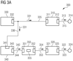
- Fig.3 shows in a block diagram an exemplary embodiment of a control system according to the proposed solution.
- a control system 300 comprises a speed power controller 310 and a speed pitch controller 320. Further, the control system 300 comprises a rotor speed sensor 330 for measuring a rotor speed like, e.g., a generator speed of the wind turbine. A signal 331 representing the measured rotor speed is generated by the rotor speed sensor 330, the signal 331 being provided via an output 332 and via a connection line 335 to an input 311 of the speed power controller 310. Based on the provided rotor speed a power reference is determined by the speed power controller 310 representing a desired output power of the wind turbine. A corresponding signal 313 representing the power reference is generated by the speed power controller 310 being forwarded via an output 312 and via a connection line 315 to a power reference terminal 314.
- a rotor speed sensor 330 for measuring a rotor speed like, e.g., a generator speed of the wind turbine.
- a signal 331 representing the measured rotor speed is generated by the rotor speed sensor 330, the
- the power reference might be derived based on further control parameters (e.g. maximum power and/or minimum power, not being part of the description here) provided to the speed power controller 310.
- the control system 300 further comprises an inflow power estimator 340 for determining a power available in an incoming wind, i.e. for determining an amount of power which can be extracted from the wind or which can be captured by the rotor.
- the signal 331 representing the measured rotor speed is further provided via a connection line 336 to an input 341 of the inflow power estimator 340.
- a signal 342 representing the estimated inflow power is generated by the inflow power estimator 340 being forwarded via an output 343 and via a connection 344 to an input 351 of an optimum pitch table 350.
- Based on the inflow power a corresponding optimum pitch angle is determined by using a lookup table as exemplarily shown in Fig.2 .
- the lookup table might be stored in a memory 355 being part of the optimum pitch table 350.
- a signal 354 representing the determined optimum pitch angle is generated by the optimum pitch table 350 being forwarded via an output 352 and via a connection line 353 to an input 321 of the speed pitch controller 320.
- a corresponding signal 322 representing a pitch reference is generated by the speed pitch controller 320, the signal 322 being forwarded via an output 325 and a connection line 323 to a pitch reference terminal 324.
- pitch reference might be derived based on further control parameters (e.g. actual rotor speed, not shown in Fig.3A ) which might be provided to the speed pitch controller 320.
- the proposed solution is based on the idea using the estimated inflow power provided by the inflow power estimator 340 as the input parameter for the optimum pitch table 350.
- the innovative aspect is the usage of the inflow power as the input parameter for deriving ("looking up") the corresponding optimum pitch angle instead of using the output power or power reference as input parameter as used in already existing solutions.
- FIG.1 A wind turbine is operated at the rotor speed 130 with the corresponding reference power 140 representing the desired output power.
- the rotor of the wind turbine is accelerating due to wind turbulences.
- the inflow power to the wind turbine is higher than the referenced power 140.
- the increased amount of the estimated inflow power (exemplarily caused by the wind turbulences) is indicated by reference 250, wherein the amount or value of the estimated inflow power 250 (which corresponds to the inflow power represented by signal 342 in Fig.3A ) is higher than the derived output power 230 without wind turbulences.
- using the inflow power 250 instead of using the reference power 230 as the input parameter to the lookup table results in a pitch angle 260 which is different from the pitch angle 240 used before the upcoming wind turbulences with increasing wind speeds.
- using the inflow power 250 as input parameter and the resulting pitch angle 260 has the potential of reducing the loading of the wind turbine.
- the lookup table as represented by the graph 200 in Fig.2 should be extended by including additional power values towards the abscissa 210 exceeding the nominal or rated power thereby allowing also the "lookup" of determined inflow power values being higher than the rated power.
- the estimated inflow power (represented by the signal 342 in Fig.3A ) denotes the power captured by the rotor which is the power input to the drive train.
- the inflow power may exceed the current output power of the wind turbine which results in a rotor acceleration.
- equation (1) doesn't consider any dynamics like, e.g., rotor accelerations.
- TSR tip-speed-ratio
- the wind speed is not a satisfactory control parameter, because of its erratic nature and the time delays in its measurements.
- the rotor acceleration ⁇ is inversely proportional to the inertia J of the rotating system and directly proportional to the difference between an aerodynamic torque applied by the wind (T inflow ) and an electric torque of the generator (T out ).
- the aerodynamic torque is affected by the operating C p .
- P out + powerlosse s represents a static inflow power representing the mechanical power going into the drive train excluding rotor acceleration.
- the determination of the inflow power as implemented in the inflow power estimator 340 may be applied according to equation (6).
- the static inflow power being part of (6) may be derived according to equation (2) or (4).
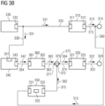
- Fig.3B shows in a block diagram an alternative exemplary embodiment of the proposed solution wherein only elements being different to Fig.3A are explained in more detail.
- the output 343 of the inflow estimator 340 is connected via a connection line 364 to an input 361 of a pitch offset logic 360.
- An output 362 of the pitch offset logic 360 is connected via a connection line 363 to an input 371 of an adding element 370 wherein an output 373 of the adding element 370 is connected via a connection line 374 to the input 321 of the speed pitch controller 320.
- the output 312 of the speed power controller 310 is additionally connected via a connection line 380 to the input 351 of the optimum pitch table 350 which output 352 is connected via a connection line 375 to an input 372 of the adding element 370.
- the signal 342 representing the estimated inflow power is forwarded to the pitch offset logic 360 instead to the optimum pitch table 350.
- the signal 313 representing the power reference is forwarded to the input 351 of the optimum pitch table 350. Consequently, a signal 382 representing an optimum pitch angle is generated according to the function as shown in Fig.2 wherein the current power reference (signal 313) is used as an input parameter for the lookup table stored in a memory 355 located in the optimum pitch table 350.
- a pitch offset is derived by the pitch offset logic 360, wherein a signal 383 is generated representing the pitch offset, the signal 383 being forwarded via the connection line 363 to the input 371 of the adding element 370.
- the provided optimum pitch angle (signal 382) and the provided pitch offset (signal 383) are added by the adding element 370 wherein a signal 384 representing the added values as an correct-ed/adapted optimum pitch angle is generated and forwarded to the input 321 of the speed pitch controller 320.
- the determination of the pitch offset being added to the optimum pitch angle is based on the following considerations: To ensure load reductions only in high load conditions (e.g. during rapid accelerations of the rotor) the optimum pitch angle is changed (further) towards feather, i.e. the pitch angle is increased, when the inflow power is sufficiently larger than the output power. Otherwise the optimum pitch angle is not affected or only marginally.
- a constant pitch offset is added to the optimum pitch angle if the inflow power is sufficiently larger that the output power.
- the lookup table 355 of the optimum pitch table 350 is modified based on the determined inflow power if the inflow power is sufficiently larger than the output power (not shown in Fig.3B ).
- a pitch offset is derived as a function of the determined inflow power being added to the optimum pitch angle.
- the lookup table 355 of the optimum pitch table 350 is modified based on the determined inflow power (not shown in Fig.3B ).
- Fig.4 shows several corresponding graphs illustrating the effectiveness of the proposed solution.
- a plot 405 visualizes a developing wind speed over time.
- an abscissa 411 represents the time [s, seconds] and an ordinate 412 represents the wind speed [m/s, meter per second].
- a graph 420 shows the rotor speed or generator speed over time.
- An abscissa 421 represents the time [s] and an ordinate 422 represents the generator speed [rpm, revolutions per minute].
- a plot 423 visualizes the resulting rotor speed without using the proposed solution.
- a plot 424 illustrates the resulting rotor speed by using the proposed solution.
- a graph 430 illustrates a power over time, wherein an abscissa 431 represents the time [s] and an ordinate 432 represents the power [kW]. Thereby, a plot 433 shows an estimated inflow power according to the proposed solution.
- a plot 434 illustrates a corresponding output power or reference power of the wind turbine.
- a graph 440 illustrates the pitch angle as derived by the speed pitch controller of Fig.3 over time.
- An abscissa 441 represents the time [s] and an ordinate 442 represents the pitch angle [deg].
- a plot 443 shows the corresponding pitch angle without using the proposed solution.
- a plot 444 illustrates the resulting pitch angle by using the proposed solution.
- abscissas 411, 421, 431, 441 do have the same time basis, i.e. the plots 405, 423, 424, 433, 434, 443, 444 of the graphs 410, 420, 430 and 440 are synchronous.
- the estimated inflow power (plot 433) is significantly higher than the output power (plot 434). This might be caused by a significant amount of energy (e.g. due to wind turbulence) being used for the acceleration of the rotor thereby increasing the rotor speed.
- the proposed solution i.e. "looking up" the pitch angle from the lookup table according to the plot 205 as exemplarily shown in Fig.2 based on the inflow power (reference number 250) instead of using the desired output power (reference number 230), the resulting optimum pitch angle (reference number 260) is significantly higher than without using the inflow estimator (reference number 240). This advantageously reduces the maximum speed and thus the loading of the wind turbine.
- the rotor speed as represented by the plot 424 is much less than the rotor speed without using the proposed solution which is represented by the plot 423.
- the optimum pitch angle according to known solutions is based on the current power output, which is delayed compared to the power captured by the rotor.
- adjustments to the optimum pitch angle are primarily made when the turbine is operating in high loads (harsh) conditions, i.e. when severe rotor accelerations occur.
- AEP Annular Energy Production
- a further aspect is the improved ability to control the rotor or generator speed by additional increment of the pitch angle compared to the pitch angle providing the highest power capture for a given operating point.
- pitching towards feather i.e. increasing the pitch angle
Description
- The invention relates to a method and to a control device for operating a wind turbine. In addition, a wind turbine, a computer program product and a computer readable medium are suggested.
- A wind turbine may comprise a wind turbine tower, a nacelle mounted on top of the wind turbine tower, a rotation shaft rotatable supported within the nacelle, wherein the rotation shaft has one or more rotor blade connected to it. Impacting wind may transfer kinetic energy to the rotor blades which cause the rotation shaft to rotate. The rotation shaft may be mechanically connected to a generator which produces electric energy upon rotation of the rotation shaft. The mechanical combination comprising the generator and the rotation shaft may be also referred to as drive train. The nacelle may be mounted at the wind turbine tower such that the nacelle may rotate around a vertical axis to direct the rotor shaft and thus the blades in the momentary wind direction which may be denoted as yawing.
- For adjusting a transfer of kinetic energy comprised in the wind to the rotation shaft via the rotor blades the rotor blades may be rotated along a longitudinal axis of the rotor blades. Rotation of the rotor blade around its longitudinal axis (which may lie within a rotation plane being a plane perpendicular to the rotation axis or the rotation shaft) may also be referred to as adjusting a rotor blade pitch angle ("pitching"). Adjusting the rotor blade pitch angle may affect an efficiency or a degree of energy transfer from the wind to the rotor blade and thus to the wind turbine.
- A variable speed wind turbine may have three different control goals (also referred to as "control strategy" or "operating strategy"), depending, e.g., on the wind speed. In low to moderate wind speeds, the control goal is maintaining a constant optimum rotor tip speed ratio (i.e. the ratio of rotor shaft speed ("rotor speed") to effective wind speed) for maximum aerodynamic efficiency. This is achieved by varying a rotor speed as the wind speed changes. In moderate winds, if the rotor reaches a rated speed before a rated power is reached, the rotor speed must be limited while the power fluctuates. The control goal is then the maintenance of approximately constant rotor speed. In moderate to high winds the control goal is the maintenance of constant rated power. This is required as the available power in the wind increases over the power conversion capabilities of the wind turbine. Additionally, transitions between these operating strategies must be managed smoothly by any successful control system design.
- The advantage that pitch regulated wind turbines have is access to two control inputs, in particular "pitch angle" and "generator torque", to achieve the aforementioned control goals.
- An optimal power production of the wind turbine at below rated power, i.e. below nominal power output may depend on the ability to apply an optimal pitch angle and track the optimal rotor tip speed ratio which depends on the effective wind speed.
- Unfortunately, it appears that the wind speed cannot be reliably measured across the rotor. To avoid using the wind speed a generator or rotor speed is used as a feedback signal for the control strategy. A corresponding control strategy is exemplarily shown by a
graph 100 inFig.1 representing a desired power production (also referred to as "output power") of a wind turbine as a function (represented by a plot 105) of a generator speed. Thereby, anabscissa 110 represents a rotational speed or the rotor or generator [rpm, revolutions per minute], an ordinate 120 represents a power reference [kW] . - The speed of a wind turbine, i.e. the rotor speed or generator speed, may be controlled by a speed power controller using the output power or power reference (also referred to as "desired output power") as a control parameter provided to a converter connected to the grid. Thereby, the speed power controller compares a speed reference and an actual generator speed. In case the actual generator speed is too low, the controller reduces the power reference. Accordingly, if the speed is too high, the controller increases the power reference.
- The speed of a wind turbine may be also controlled by a speed pitch controller using a pitch reference as a control parameter to adjust a pitch angle or pitch position of the blades. By doing this it is possible to control an amount of energy being captured from the wind. If the generator or rotor speed is too high, at least one blade will be pitched out of the wind by increasing the blade pitch angle. Accordingly, at least one blade will be pitched in the wind by decreasing the blade pitch angle in case the speed is too low.
- The adjustment of an optimum pitch angle is usually based on a lookup table with a fixed configuration enabling a compromise between reducing loads on the wind turbine as well as reducing acoustic noise and maximizing power production. The lookup table might be stored in a memory located, e.g., in the speed pitch controller.
- The pitch angle being derived ("looked up") from the lookup table is a function of power corresponding to the actual output power of the wind turbine. As an example, an instantaneous or low-pass filtered output power of the wind turbine or generator might be used to derive or "look up" a corresponding pitch angel in the lookup table.
-
Fig.2 exemplarily shows agraph 200 representing an optimum pitch angle ([deg], represented by an ordinate 220) as a function (represented by a plot 205) of an output power ([kW], represented by an abscissa 210). As an example, according to known control strategies for variable speed wind turbines (seeFig.1 ), a desiredoutput power 140 is determined by the speed power controller based on anactual rotor speed 130. Assuming that thedetermined output power 140 is provided as the power reference to the converter a correspondingoptimum pitch angle 240 will be derived according to theplot 205 of thegraph 200 wherein thederived output power 140 ofgraph 100 is used as aninput parameter 230 in thegraph 200. - Due to the usage of the output power as a basis for deriving the optimum pitch angle, the control of the wind turbine might be delayed.
- The object is thus to overcome such disadvantage and in particular to provide an improved approach for operating a wind turbine. Documents
WO2009/153614 andEP2365215 are prior art examples in controlling wind turbines. - This problem is solved according to the features of the independent claims. Further embodiments result from the depending claims.
- In order to overcome this problem, a method is provided for operating a wind turbine, wherein
- an inflow power to the wind turbine is determined,
- a pitch angle of at least one rotor blade of the wind turbine is derived based on the inflow power.
- At least one rotor blade of the wind turbine is adjusted according to the derived pitch angle, i.e. the operation of the wind turbine is controlled based on the determined inflow power.
- By determining or estimating the input power to the wind turbine instead of using the derived output power of the wind turbine the adjustment of the pitch angle (which is also referred to as optimum pitch angle hereinafter) may react faster to rotor accelerations. Reacting faster to rotor accelerations reduces the maximum power input, e.g., to the drive train of the wind turbine which consequently reduces the structural loading on the wind turbine. Reducing the structural loading and thus reducing the rotor acceleration will also minimize the risk of over speed events which results in an improved turbine availability.
- In an embodiment, the determined inflow power is used as an input parameter for deriving the pitch angle as a function of output power of the wind turbine.
- In another embodiment,
- the function of power is represented by a lookup table,
- the pitch angle is derived by using the inflow power as input parameter to the lookup table.
- Pursuant to another embodiment, the lookup table comprises power values exceeding the rated power of the wind turbine.
- The lookup table may be an optimum pitch angle lookup table.
- An optimum pitch angle is usually a function of output power which is limited by the rated power of the wind turbine. Using the proposed inflow power for deriving or determining the pitch angle by a lookup in the lookup table might require an extension of power values that exceed the rated power. Defining as an example conservative pitch angle values correlating to power values exceeding the rated power may result to pitch angles enabling load reductions when the inflow power exceed the output power.
- According to a further possible embodiment,
- a pitch offset is determined based on the inflow power,
- the pitch angle of the at least one rotor blade is derived by adding the pitch offset to a further pitch angle determined based on a power output of the wind turbine.
- The further pitch angle may be determined according to known solutions already explained above in relation to
Fig.1 and Fig.2 thereby using the power output of the wind turbine as input parameter to thefunction 205 of thegraph 200. According to the proposed solution, pitch offset is determined based on the inflow power wherein the further pitch angle is adjusted or corrected based on the pitch offset. The adjustment may be a simple adding of the pitch offset to the further pitch angle. It should be noted that alternative mathematical operations may be applied like, e.g., multiplication. - According to the invention, the inflow power is determined based on a rotor acceleration of the wind turbine.
- In a next embodiment, the inflow power is determined based on an output power and a rotational inertia of the wind turbine. It is also an embodiment that the inflow power is determined based on the following equation

- Pinflow
- represents the inflow power corresponding to the mechanical power going into the drive train,
- Pout
- corresponds to the output power of the wind turbine which might be the electrical output power of the wind turbine,
- J
- corresponds to the rotational inertia of the wind turbine including rotor, drive train, etc.,
- ω̇
- corresponds to the acceleration of the rotor, and
- power losses
- correspond to friction and electrical losses.
- Pursuant to another embodiment, the pitch angle is derived during power production of the wind turbine at below rated power.
- The problem stated above is also solved by a wind turbine comprising a processing unit that is arranged for
- determining an inflow power to the wind turbine
- deriving a pitch angle of at least one rotor blade based on the inflow power.
- The problem stated supra is also solved by a control device comprising and/or being associated with a processor unit and/or hard-wired circuit and/or a logic device that is arranged such that the method as described herein is executable thereon.
- It is noted that said processing unit can comprise at least one, in particular several means that are arranged to execute the steps of the method described herein. The means may be logically or physically separated; in particular several logically separate means could be combined in at least one physical unit.
- Said processing unit may comprise at least one of the following: a processor, a microcontroller, a hard-wired circuit, an ASIC, an FPGA, a logic device.
- The solution provided herein further comprises a computer program product directly loadable into a memory of a digital computer, comprising software code portions for performing the steps of the method as described herein.
- In addition, the problem stated above is solved by a computer-readable medium, e.g., storage of any kind, having computer-executable instructions adapted to cause a computer system to perform the method as described herein.
- Furthermore, the problem stated above is solved by a system comprising at least one device as described herein.
- Embodiments of the invention are shown and illustrated in the following figures:
- Fig.1
- shows a graph representing a desired output power production of a wind turbine according to an exemplary control strategy;
- Fig.2
- exemplary shows a graph representing an optimum pitch angle as a function of output power;
- Fig.3A
- shows in a block diagram an exemplary embodiment of a control system according to the proposed solution;
- Fig.3B
- shows in a block diagram an alternative exemplary embodiment of the control system;
- Fig.4
- shows several corresponding graphs illustrating the effectiveness of the proposed solution.
-
Fig.3 shows in a block diagram an exemplary embodiment of a control system according to the proposed solution. - A
control system 300 comprises aspeed power controller 310 and aspeed pitch controller 320. Further, thecontrol system 300 comprises arotor speed sensor 330 for measuring a rotor speed like, e.g., a generator speed of the wind turbine. Asignal 331 representing the measured rotor speed is generated by therotor speed sensor 330, thesignal 331 being provided via anoutput 332 and via aconnection line 335 to aninput 311 of thespeed power controller 310. Based on the provided rotor speed a power reference is determined by thespeed power controller 310 representing a desired output power of the wind turbine. Acorresponding signal 313 representing the power reference is generated by thespeed power controller 310 being forwarded via anoutput 312 and via aconnection line 315 to apower reference terminal 314. - It should be noted that the power reference might be derived based on further control parameters (e.g. maximum power and/or minimum power, not being part of the description here) provided to the
speed power controller 310. - The
control system 300 further comprises aninflow power estimator 340 for determining a power available in an incoming wind, i.e. for determining an amount of power which can be extracted from the wind or which can be captured by the rotor. For that, thesignal 331 representing the measured rotor speed is further provided via aconnection line 336 to aninput 341 of theinflow power estimator 340. Based on the provided rotor speed asignal 342 representing the estimated inflow power is generated by theinflow power estimator 340 being forwarded via anoutput 343 and via aconnection 344 to aninput 351 of an optimum pitch table 350. Based on the inflow power a corresponding optimum pitch angle is determined by using a lookup table as exemplarily shown inFig.2 . The lookup table might be stored in amemory 355 being part of the optimum pitch table 350. - Further on, a
signal 354 representing the determined optimum pitch angle is generated by the optimum pitch table 350 being forwarded via anoutput 352 and via aconnection line 353 to aninput 321 of thespeed pitch controller 320. Based on the provided optimum pitch angle acorresponding signal 322 representing a pitch reference is generated by thespeed pitch controller 320, thesignal 322 being forwarded via anoutput 325 and aconnection line 323 to apitch reference terminal 324. - It should be noted that the pitch reference might be derived based on further control parameters (e.g. actual rotor speed, not shown in
Fig.3A ) which might be provided to thespeed pitch controller 320. - The proposed solution is based on the idea using the estimated inflow power provided by the
inflow power estimator 340 as the input parameter for the optimum pitch table 350. Thus, the innovative aspect is the usage of the inflow power as the input parameter for deriving ("looking up") the corresponding optimum pitch angle instead of using the output power or power reference as input parameter as used in already existing solutions. By avoiding the necessary processing time being mandatory for applying the referenced output power for operating the wind turbine a faster reaction to rotor accelerations is possible which beneficially results, e.g., in a faster adjustment of the pitch angle and therefore in a general reduction of loads. - For further explanation reference is made again to
Fig.1 and Fig.2 thereby assuming the following exemplary scenario:
A wind turbine is operated at therotor speed 130 with thecorresponding reference power 140 representing the desired output power. However, in the present scenario the rotor of the wind turbine is accelerating due to wind turbulences. As a consequence, the inflow power to the wind turbine is higher than the referencedpower 140. InFig.2 the increased amount of the estimated inflow power (exemplarily caused by the wind turbulences) is indicated byreference 250, wherein the amount or value of the estimated inflow power 250 (which corresponds to the inflow power represented bysignal 342 inFig.3A ) is higher than the derivedoutput power 230 without wind turbulences. Consequently, using theinflow power 250 instead of using thereference power 230 as the input parameter to the lookup table results in apitch angle 260 which is different from thepitch angle 240 used before the upcoming wind turbulences with increasing wind speeds. Advantageously, using theinflow power 250 as input parameter and the resultingpitch angle 260 has the potential of reducing the loading of the wind turbine. - According to an advantageous embodiment, the lookup table as represented by the
graph 200 inFig.2 should be extended by including additional power values towards theabscissa 210 exceeding the nominal or rated power thereby allowing also the "lookup" of determined inflow power values being higher than the rated power. - The estimated inflow power (represented by the
signal 342 inFig.3A ) denotes the power captured by the rotor which is the power input to the drive train. - Due to, e.g., upcoming wind turbulences and thus increasing wind speeds the inflow power may exceed the current output power of the wind turbine which results in a rotor acceleration.
- The larger the amount of inflow power is in relation to the output power the greater the rotor acceleration and thus the structural loading of the wind turbine.
- An output power Pout converted by a wind turbine is related to the wind speed as shown in the following equation:
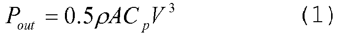
- ρ = mass density of air,
- A = area swept by the rotor blades,
- V = wind speed,
- Cp = no dimensional power coefficient
- It should be noted that aforementioned equation (1) doesn't consider any dynamics like, e.g., rotor accelerations.
- For a variable speed turbine, the objective is to operate near maximum efficiency, where the resulting target power and thus the output power Pout can be expressed as shown in the following equation:

- ρ = mass density of air,
- R = rotor radius measured at the blade tip,
- w = rotational speed of the blade,
- A = area swept by the rotor blades,
- Cp = no dimensional power coefficient
- The tip-speed-ratio (TSR), which is a no dimensional tip speed, is defined as the ratio between the rectilinear speed of the blade tip and the wind speed:

- According to equation (2) the power at any wind speed is maximized by operating near tip speed ratio that results in the maximum power coefficient. For a variable speed turbine, this means that as the wind speed changes, the rotor speed should be adjusted proportionally.
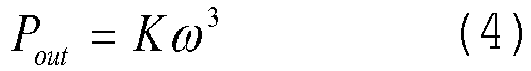
- In the practical matter of operating a wind turbine, the wind speed is not a satisfactory control parameter, because of its erratic nature and the time delays in its measurements. However, by simple manipulation of the aforementioned equations, the output power Pout of (2) can be expressed as a function of the rotor speed ω, a reliable and easily measured control parameter:
- It should be noted that rotor acceleration ω̇ might be minimized as long as the power extracted from the wind, less drive train losses, is equal to the output power and thus the electric power output of the generator. This relation is described by the following equation in terms of torque:

- The rotor acceleration ω̇ is inversely proportional to the inertia J of the rotating system and directly proportional to the difference between an aerodynamic torque applied by the wind (Tinflow) and an electric torque of the generator (Tout). The aerodynamic torque is affected by the operating Cp.
- In terms of power, equation (5) may be rewritten as follows:

- Pinflow
- represents the inflow power corresponding to the mechanical power going into the drive train,
- Pout
- corresponds to the output power of the wind turbine which might be the electrical output power of the wind turbine,
- J
- corresponds to the rotational inertia of the wind turbine including rotor, drive train, etc.,
- ω̇
- corresponds to the acceleration of the rotor, and
- power losses
- correspond to friction and electrical losses.
- The term (Pout + powerlosse s) represents a static inflow power representing the mechanical power going into the drive train excluding rotor acceleration.
- It should be noted that the determination of the inflow power as implemented in the
inflow power estimator 340 may be applied according to equation (6). Thereby, the static inflow power being part of (6) may be derived according to equation (2) or (4). -
Fig.3B shows in a block diagram an alternative exemplary embodiment of the proposed solution wherein only elements being different toFig.3A are explained in more detail. - Contrary to
Fig.3A theoutput 343 of theinflow estimator 340 is connected via aconnection line 364 to aninput 361 of a pitch offsetlogic 360. Anoutput 362 of the pitch offsetlogic 360 is connected via aconnection line 363 to aninput 371 of an adding element 370 wherein anoutput 373 of the adding element 370 is connected via aconnection line 374 to theinput 321 of thespeed pitch controller 320. - Further, the
output 312 of thespeed power controller 310 is additionally connected via aconnection line 380 to theinput 351 of the optimum pitch table 350 whichoutput 352 is connected via aconnection line 375 to aninput 372 of the adding element 370. - In contrast to the embodiment of
Fig.3A thesignal 342 representing the estimated inflow power is forwarded to the pitch offsetlogic 360 instead to the optimum pitch table 350. Further, thesignal 313 representing the power reference is forwarded to theinput 351 of the optimum pitch table 350. Consequently, asignal 382 representing an optimum pitch angle is generated according to the function as shown inFig.2 wherein the current power reference (signal 313) is used as an input parameter for the lookup table stored in amemory 355 located in the optimum pitch table 350. - In addition to the optimum pitch angle represented by signal 382 a pitch offset is derived by the pitch offset
logic 360, wherein asignal 383 is generated representing the pitch offset, thesignal 383 being forwarded via theconnection line 363 to theinput 371 of the adding element 370. The provided optimum pitch angle (signal 382) and the provided pitch offset (signal 383) are added by the adding element 370 wherein a signal 384 representing the added values as an correct-ed/adapted optimum pitch angle is generated and forwarded to theinput 321 of thespeed pitch controller 320. - The determination of the pitch offset being added to the optimum pitch angle is based on the following considerations:
To ensure load reductions only in high load conditions (e.g. during rapid accelerations of the rotor) the optimum pitch angle is changed (further) towards feather, i.e. the pitch angle is increased, when the inflow power is sufficiently larger than the output power. Otherwise the optimum pitch angle is not affected or only marginally. - As an example, two possible solutions can be applied based on the embodiment of
Fig.3B : - A constant pitch offset is added to the optimum pitch angle if the inflow power is sufficiently larger that the output power. Alternatively or in addition to that the lookup table 355 of the optimum pitch table 350 is modified based on the determined inflow power if the inflow power is sufficiently larger than the output power (not shown in
Fig.3B ). - A pitch offset is derived as a function of the determined inflow power being added to the optimum pitch angle. Alternatively or in addition to that the lookup table 355 of the optimum pitch table 350 is modified based on the determined inflow power (not shown in
Fig.3B ). -
Fig.4 shows several corresponding graphs illustrating the effectiveness of the proposed solution. - Within a graph 410 a
plot 405 visualizes a developing wind speed over time. Thereby, anabscissa 411 represents the time [s, seconds] and anordinate 412 represents the wind speed [m/s, meter per second]. - A
graph 420 shows the rotor speed or generator speed over time. Anabscissa 421 represents the time [s] and anordinate 422 represents the generator speed [rpm, revolutions per minute]. Thereby aplot 423 visualizes the resulting rotor speed without using the proposed solution. Additionally, aplot 424 illustrates the resulting rotor speed by using the proposed solution. - A
graph 430 illustrates a power over time, wherein anabscissa 431 represents the time [s] and anordinate 432 represents the power [kW]. Thereby, aplot 433 shows an estimated inflow power according to the proposed solution. Aplot 434 illustrates a corresponding output power or reference power of the wind turbine. - A
graph 440 illustrates the pitch angle as derived by the speed pitch controller ofFig.3 over time. Anabscissa 441 represents the time [s] and anordinate 442 represents the pitch angle [deg]. Aplot 443 shows the corresponding pitch angle without using the proposed solution. Aplot 444 illustrates the resulting pitch angle by using the proposed solution. - It should be noted that the
abscissas plots graphs - According to
graph 430 the estimated inflow power (plot 433) is significantly higher than the output power (plot 434). This might be caused by a significant amount of energy (e.g. due to wind turbulence) being used for the acceleration of the rotor thereby increasing the rotor speed. Applying the proposed solution, i.e. "looking up" the pitch angle from the lookup table according to theplot 205 as exemplarily shown inFig.2 based on the inflow power (reference number 250) instead of using the desired output power (reference number 230), the resulting optimum pitch angle (reference number 260) is significantly higher than without using the inflow estimator (reference number 240). This advantageously reduces the maximum speed and thus the loading of the wind turbine. - According to the
graph 420 ofFig.4 , the rotor speed as represented by theplot 424 is much less than the rotor speed without using the proposed solution which is represented by theplot 423. - The optimum pitch angle according to known solutions is based on the current power output, which is delayed compared to the power captured by the rotor. By estimating the inflow power, i.e. input power to the drive train and using the inflow power for lookup in the optimum pitch table/curve according to the proposed solution enables load reduction during increasing wind speeds ("gusts").
- According to a further aspect of the proposed solution, adjustments to the optimum pitch angle are primarily made when the turbine is operating in high loads (harsh) conditions, i.e. when severe rotor accelerations occur. As a consequence, the effect on "Annular Energy Production (AEP)" is minimized compared to a constant adjustment of the optimum pitch angle.
- For gentle conditions there will either be no or only a minor impact on the optimum pitch angle wherein the risk of over speed events is reduced and ultimate loads are lowered. Due to the proposed ongoing or online inflow power estimation it is possible to react to situations tougher than anticipated or forecasted for a specific site or design which results in increased safety against structural failure.
- A further aspect is the improved ability to control the rotor or generator speed by additional increment of the pitch angle compared to the pitch angle providing the highest power capture for a given operating point. This results in an improved sensitivity. Hence, pitching towards feather (i.e. increasing the pitch angle) relative to this optimum point will reduce the power capture of the rotor and further will increase the sensitivity of the pitch to control the power inflow, i.e. the sensitivity to control the speed of the wind turbine. Therefore it may be beneficial to increase the optimum pitch angle for a operating point close the rated wind speed to prevent severe loading and risk of over speed when the wind picks up close to rated wind speeds.
- Although the invention is described in detail by the embodiments above, it is noted that the invention is not at all limited to such embodiments. In particular, alternatives can be derived by a person skilled in the art from the exemplary embodiments and the illustrations without exceeding the scope of this invention as defined by the appended claims.
Claims (11)
- A method for operating a wind turbine, wherein- an inflow power (342) to the wind turbine is determined, wherein the inflow power is representing a power available in an incoming wind,- a pitch angle (354, 384) of at least one rotor blade of the wind turbine is derived based on the inflow power (342),- the inflow power (342) is determined based on a rotor acceleration of the wind turbine.
- The method according to claim 1, wherein
the determined inflow power (342) is used as an input parameter for deriving the pitch angle (354) as a function (205) of output power of the wind turbine. - The method according to claim 2, wherein- the function (205) of power is represented by a lookup table (200),- the pitch angle (354) is derived by using the inflow power (342) as input parameter to the lookup table.
- The method according to claim 3, wherein
the lookup table (200) comprises power values exceeding the rated power of the wind turbine. - The method according to claim 1, wherein- a pitch offset (383) is determined based on the inflow power (242),- the pitch angle (384) of the at least one rotor blade is derived by adding the pitch offset (383) to a further pitch angle (382) determined based on a power output (313) of the wind turbine.
- The method according to any of the proceeding claims, wherein
the inflow power (342) is determined based on an output power and a rotational inertia of the wind turbine. - The method according to claim 6, wherein the inflow power (342) is determined based on the following equation
 Pinflow represents the inflow power (342) corresponding to the mechanical power going into the drive train,Pout corresponds to the output power of the wind turbine which might be the electrical output power of the wind turbine,J corresponds to the rotational inertia of the wind turbine including rotor, drive train, etc.,ω̇ corresponds to the acceleration of the rotor, andpower losses correspond to friction and electrical losses.
 - A Wind turbine comprising
a processing unit that is arranged for- determining an inflow power (342) to the wind turbine, wherein the inflow power is representing a power available in an incoming wind,- deriving a pitch angle (354, 384) of at least one rotor blade of the wind turbine based on the inflow power (342),- the inflow power (342) is determined based on a rotor acceleration of the wind turbine. - A control device comprising and/or being associated with a processor unit and/or hard-wired circuit and/or a logic device that is arranged such that the method according to any of the preceding claims 1 to 7 is executable thereon.
- A computer program product directly loadable into a memory of a digital computer, comprising software code portions for performing the steps of the method according to any of the claims 1 to 7.
- A computer readable medium, having computer-executable instructions adapted to cause a computer system to perform the steps of the method according to any of the claims 1 to 7.
Priority Applications (2)
| Application Number | Priority Date | Filing Date | Title |
|---|---|---|---|
| EP15173728.5A EP3109461B1 (en) | 2015-06-25 | 2015-06-25 | Operating a wind turbine |
| DK15173728.5T DK3109461T3 (en) | 2015-06-25 | 2015-06-25 | OPERATION OF A WINDMILL |
Applications Claiming Priority (1)
| Application Number | Priority Date | Filing Date | Title |
|---|---|---|---|
| EP15173728.5A EP3109461B1 (en) | 2015-06-25 | 2015-06-25 | Operating a wind turbine |
Publications (2)
| Publication Number | Publication Date |
|---|---|
| EP3109461A1 EP3109461A1 (en) | 2016-12-28 |
| EP3109461B1 true EP3109461B1 (en) | 2023-08-16 |
Family
ID=53487288
Family Applications (1)
| Application Number | Title | Priority Date | Filing Date |
|---|---|---|---|
| EP15173728.5A Active EP3109461B1 (en) | 2015-06-25 | 2015-06-25 | Operating a wind turbine |
Country Status (2)
| Country | Link |
|---|---|
| EP (1) | EP3109461B1 (en) |
| DK (1) | DK3109461T3 (en) |
Families Citing this family (2)
| Publication number | Priority date | Publication date | Assignee | Title |
|---|---|---|---|---|
| EP3839249B1 (en) * | 2019-12-20 | 2023-10-11 | Wobben Properties GmbH | Method for adjusting a pitch angle of a rotor blade, control device for adjusting a pitch angle and wind turbine therefor |
| CN113565699B (en) * | 2021-08-13 | 2023-09-12 | 远景智能国际私人投资有限公司 | Method, device and system for detecting pitch angle of wind generating set |
Family Cites Families (5)
| Publication number | Priority date | Publication date | Assignee | Title |
|---|---|---|---|---|
| WO2009153614A2 (en) * | 2008-06-20 | 2009-12-23 | Clipper Windpower Technology, Inc. | Means and method of wind turbine control for maximum power acquisition |
| EP2339743B1 (en) * | 2008-10-16 | 2018-07-25 | Mitsubishi Heavy Industries, Ltd. | Wind power generation system, and its control method |
| EP2282053B1 (en) * | 2009-06-29 | 2016-01-13 | Vestas Wind Systems A/S | Wind turbine providing grid support |
| DK2365215T3 (en) * | 2010-03-10 | 2013-01-28 | Siemens Ag | Controlling the rotational speed of a wind turbine based on rotor acceleration |
| EP2872775B1 (en) * | 2012-09-28 | 2016-05-25 | Siemens Aktiengesellschaft | Method and arrangement for controlling a wind turbine |
-
2015
- 2015-06-25 DK DK15173728.5T patent/DK3109461T3/en active
- 2015-06-25 EP EP15173728.5A patent/EP3109461B1/en active Active
Also Published As
| Publication number | Publication date |
|---|---|
| DK3109461T3 (en) | 2023-10-16 |
| EP3109461A1 (en) | 2016-12-28 |
Similar Documents
| Publication | Publication Date | Title |
|---|---|---|
| EP2444659B1 (en) | Method and system for adjusting a power parameter of a wind turbine | |
| EP2520795B1 (en) | Method and computing module for determining pitch angle adjustment signals of a wind turbine based on the maximum rotational speed | |
| AU2013329754B2 (en) | Method for operating a wind turbine | |
| EP2154362B1 (en) | Wind power generator, wind power generation system, and generation control method of wind power generator | |
| EP2712403B1 (en) | Power management system for yaw controlled wind turbines | |
| US8128362B2 (en) | Method of operating a wind turbine, a wind turbine and a cluster of wind turbines | |
| EP2859225B1 (en) | A method of operating a wind turbine as well as a system suitable therefore | |
| EP3412909B1 (en) | System and method for reducing wind turbine noise during high wind speed conditions | |
| EP3199806B1 (en) | Wind turbine power generating apparatus and method of operating the same | |
| US20130193686A1 (en) | System and methods for determining pitch angles for a wind turbine during peak shaving | |
| CN107407258B (en) | Power ramp of turbine from low power mode | |
| US10024303B2 (en) | Method and device for controlling floating body wind turbine power generating apparatus, and floating body wind turbine power generating apparatus | |
| EP2636893A1 (en) | Method to control the operation of a wind turbine | |
| JP5107271B2 (en) | Wind power generator, blade pitch angle control method thereof, and program | |
| JP2006233912A (en) | Wind turbine generator, its control method, and method for controlling pitch-angle of blade | |
| EP3221581B1 (en) | A method for estimating a wind speed in a stable manner | |
| US20150050145A1 (en) | Method for operating a wind turbine, and a corresponding wind turbine | |
| JP6314104B2 (en) | Wind power generation facility and control method for wind power generation facility | |
| EP3109461B1 (en) | Operating a wind turbine | |
| JP5550501B2 (en) | Horizontal axis windmill | |
| EP3812579A1 (en) | System and method for improved extreme load control for wind turbine components | |
| US10704533B2 (en) | Wind turbine power generating apparatus and method of operating the same | |
| JP6462388B2 (en) | Wind power generator | |
| EP3728838B1 (en) | Applying wind turbine yaw moment via pitching | |
| JP2017180151A (en) | Wind power generator, wind farm, or wind power generator operating method |
Legal Events
| Date | Code | Title | Description |
|---|---|---|---|
| PUAI | Public reference made under article 153(3) epc to a published international application that has entered the european phase |
Free format text: ORIGINAL CODE: 0009012 |
|
| STAA | Information on the status of an ep patent application or granted ep patent |
Free format text: STATUS: THE APPLICATION HAS BEEN PUBLISHED |
|
| AK | Designated contracting states |
Kind code of ref document: A1 Designated state(s): AL AT BE BG CH CY CZ DE DK EE ES FI FR GB GR HR HU IE IS IT LI LT LU LV MC MK MT NL NO PL PT RO RS SE SI SK SM TR |
|
| AX | Request for extension of the european patent |
Extension state: BA ME |
|
| STAA | Information on the status of an ep patent application or granted ep patent |
Free format text: STATUS: REQUEST FOR EXAMINATION WAS MADE |
|
| 17P | Request for examination filed |
Effective date: 20170626 |
|
| RBV | Designated contracting states (corrected) |
Designated state(s): AL AT BE BG CH CY CZ DE DK EE ES FI FR GB GR HR HU IE IS IT LI LT LU LV MC MK MT NL NO PL PT RO RS SE SI SK SM TR |
|
| RAP1 | Party data changed (applicant data changed or rights of an application transferred) |
Owner name: SIEMENS AKTIENGESELLSCHAFT |
|
| RAP1 | Party data changed (applicant data changed or rights of an application transferred) |
Owner name: SIEMENS GAMESA RENEWABLE ENERGY A/S |
|
| STAA | Information on the status of an ep patent application or granted ep patent |
Free format text: STATUS: EXAMINATION IS IN PROGRESS |
|
| STAA | Information on the status of an ep patent application or granted ep patent |
Free format text: STATUS: EXAMINATION IS IN PROGRESS |
|
| 17Q | First examination report despatched |
Effective date: 20201027 |
|
| STAA | Information on the status of an ep patent application or granted ep patent |
Free format text: STATUS: EXAMINATION IS IN PROGRESS |
|
| GRAP | Despatch of communication of intention to grant a patent |
Free format text: ORIGINAL CODE: EPIDOSNIGR1 |
|
| STAA | Information on the status of an ep patent application or granted ep patent |
Free format text: STATUS: GRANT OF PATENT IS INTENDED |
|
| INTG | Intention to grant announced |
Effective date: 20230317 |
|
| GRAS | Grant fee paid |
Free format text: ORIGINAL CODE: EPIDOSNIGR3 |
|
| GRAA | (expected) grant |
Free format text: ORIGINAL CODE: 0009210 |
|
| STAA | Information on the status of an ep patent application or granted ep patent |
Free format text: STATUS: THE PATENT HAS BEEN GRANTED |
|
| AK | Designated contracting states |
Kind code of ref document: B1 Designated state(s): AL AT BE BG CH CY CZ DE DK EE ES FI FR GB GR HR HU IE IS IT LI LT LU LV MC MK MT NL NO PL PT RO RS SE SI SK SM TR |
|
| REG | Reference to a national code |
Ref country code: GB Ref legal event code: FG4D |
|
| REG | Reference to a national code |
Ref country code: CH Ref legal event code: EP |
|
| REG | Reference to a national code |
Ref country code: DE Ref legal event code: R096 Ref document number: 602015085129 Country of ref document: DE |
|
| REG | Reference to a national code |
Ref country code: IE Ref legal event code: FG4D |
|
| REG | Reference to a national code |
Ref country code: DK Ref legal event code: T3 Effective date: 20231009 |
|
| REG | Reference to a national code |
Ref country code: LT Ref legal event code: MG9D |
|
| REG | Reference to a national code |
Ref country code: NL Ref legal event code: MP Effective date: 20230816 |
|
| REG | Reference to a national code |
Ref country code: AT Ref legal event code: MK05 Ref document number: 1600286 Country of ref document: AT Kind code of ref document: T Effective date: 20230816 |
|
| PG25 | Lapsed in a contracting state [announced via postgrant information from national office to epo] |
Ref country code: GR Free format text: LAPSE BECAUSE OF FAILURE TO SUBMIT A TRANSLATION OF THE DESCRIPTION OR TO PAY THE FEE WITHIN THE PRESCRIBED TIME-LIMIT Effective date: 20231117 |
|
| PG25 | Lapsed in a contracting state [announced via postgrant information from national office to epo] |
Ref country code: IS Free format text: LAPSE BECAUSE OF FAILURE TO SUBMIT A TRANSLATION OF THE DESCRIPTION OR TO PAY THE FEE WITHIN THE PRESCRIBED TIME-LIMIT Effective date: 20231216 |
|
| PG25 | Lapsed in a contracting state [announced via postgrant information from national office to epo] |
Ref country code: SE Free format text: LAPSE BECAUSE OF FAILURE TO SUBMIT A TRANSLATION OF THE DESCRIPTION OR TO PAY THE FEE WITHIN THE PRESCRIBED TIME-LIMIT Effective date: 20230816 Ref country code: RS Free format text: LAPSE BECAUSE OF FAILURE TO SUBMIT A TRANSLATION OF THE DESCRIPTION OR TO PAY THE FEE WITHIN THE PRESCRIBED TIME-LIMIT Effective date: 20230816 Ref country code: PT Free format text: LAPSE BECAUSE OF FAILURE TO SUBMIT A TRANSLATION OF THE DESCRIPTION OR TO PAY THE FEE WITHIN THE PRESCRIBED TIME-LIMIT Effective date: 20231218 Ref country code: NO Free format text: LAPSE BECAUSE OF FAILURE TO SUBMIT A TRANSLATION OF THE DESCRIPTION OR TO PAY THE FEE WITHIN THE PRESCRIBED TIME-LIMIT Effective date: 20231116 Ref country code: NL Free format text: LAPSE BECAUSE OF FAILURE TO SUBMIT A TRANSLATION OF THE DESCRIPTION OR TO PAY THE FEE WITHIN THE PRESCRIBED TIME-LIMIT Effective date: 20230816 Ref country code: LV Free format text: LAPSE BECAUSE OF FAILURE TO SUBMIT A TRANSLATION OF THE DESCRIPTION OR TO PAY THE FEE WITHIN THE PRESCRIBED TIME-LIMIT Effective date: 20230816 Ref country code: LT Free format text: LAPSE BECAUSE OF FAILURE TO SUBMIT A TRANSLATION OF THE DESCRIPTION OR TO PAY THE FEE WITHIN THE PRESCRIBED TIME-LIMIT Effective date: 20230816 Ref country code: IS Free format text: LAPSE BECAUSE OF FAILURE TO SUBMIT A TRANSLATION OF THE DESCRIPTION OR TO PAY THE FEE WITHIN THE PRESCRIBED TIME-LIMIT Effective date: 20231216 Ref country code: HR Free format text: LAPSE BECAUSE OF FAILURE TO SUBMIT A TRANSLATION OF THE DESCRIPTION OR TO PAY THE FEE WITHIN THE PRESCRIBED TIME-LIMIT Effective date: 20230816 Ref country code: GR Free format text: LAPSE BECAUSE OF FAILURE TO SUBMIT A TRANSLATION OF THE DESCRIPTION OR TO PAY THE FEE WITHIN THE PRESCRIBED TIME-LIMIT Effective date: 20231117 Ref country code: FI Free format text: LAPSE BECAUSE OF FAILURE TO SUBMIT A TRANSLATION OF THE DESCRIPTION OR TO PAY THE FEE WITHIN THE PRESCRIBED TIME-LIMIT Effective date: 20230816 Ref country code: AT Free format text: LAPSE BECAUSE OF FAILURE TO SUBMIT A TRANSLATION OF THE DESCRIPTION OR TO PAY THE FEE WITHIN THE PRESCRIBED TIME-LIMIT Effective date: 20230816 |
|
| PG25 | Lapsed in a contracting state [announced via postgrant information from national office to epo] |
Ref country code: PL Free format text: LAPSE BECAUSE OF FAILURE TO SUBMIT A TRANSLATION OF THE DESCRIPTION OR TO PAY THE FEE WITHIN THE PRESCRIBED TIME-LIMIT Effective date: 20230816 |