US8446419B2 - Image processing system and method - Google Patents
Image processing system and method Download PDFInfo
- Publication number
- US8446419B2 US8446419B2 US12/637,577 US63757709A US8446419B2 US 8446419 B2 US8446419 B2 US 8446419B2 US 63757709 A US63757709 A US 63757709A US 8446419 B2 US8446419 B2 US 8446419B2
- Authority
- US
- United States
- Prior art keywords
- texture
- information
- vertex
- ultrasound
- textures
- Prior art date
- Legal status (The legal status is an assumption and is not a legal conclusion. Google has not performed a legal analysis and makes no representation as to the accuracy of the status listed.)
- Expired - Fee Related, expires
Links
Images


Classifications
-
- G—PHYSICS
- G06—COMPUTING; CALCULATING OR COUNTING
- G06T—IMAGE DATA PROCESSING OR GENERATION, IN GENERAL
- G06T1/00—General purpose image data processing
-
- G—PHYSICS
- G06—COMPUTING; CALCULATING OR COUNTING
- G06T—IMAGE DATA PROCESSING OR GENERATION, IN GENERAL
- G06T1/00—General purpose image data processing
- G06T1/20—Processor architectures; Processor configuration, e.g. pipelining
-
- A—HUMAN NECESSITIES
- A61—MEDICAL OR VETERINARY SCIENCE; HYGIENE
- A61B—DIAGNOSIS; SURGERY; IDENTIFICATION
- A61B8/00—Diagnosis using ultrasonic, sonic or infrasonic waves
- A61B8/13—Tomography
Definitions
- the present disclosure relates to image processing systems, and more particularly to a system and method of filtering data by using a graphic processing unit (GPU).
- GPU graphic processing unit
- An image processing system is a system that processes digital data to provide an image. It has been used in various fields.
- An image processing system for ultrasound diagnosis is described herein as an example of image processing system.
- an ultrasound system Due to its non-invasive and non-destructive nature, an ultrasound system has been extensively used in the medical field to acquire internal information of a target object.
- the ultrasound system is used in the medical field since it can provide doctors with a high resolution image of internal tissues of the target object without the need of surgical treatment.
- the ultrasound system includes an ultrasound probe, a beam former, a data processing unit, a scan converting unit and a display unit.
- the ultrasound probe transmits an ultrasound signal to the target object and receives the ultrasound signal reflected by the target object (i.e., an ultrasound echo signal), thereby forming a received signal.
- the ultrasound probe includes at least one transducer element, which operates to interconvert between the ultrasound signal and the electrical signal.
- the beam former analog/digital converts the received signal provided from the ultrasound probe. It then time-delays the digital signal considering the location and the focal point of each transducer element and adds up the time-delayed digital signal, thereby forming ultrasound data (i.e., RF data).
- the data processing unit performs various data processing operations on the ultrasound data needed to form an ultrasound image.
- the scan converting unit scan-converts the ultrasound data so that the data-processed ultrasound data can be displayed within the display area of the display unit.
- the display unit displays the scan-converted ultrasound data as an ultrasound image on the screen.
- the data processing and scan-converting of ultrasound data have been recently performed by using a graphic processing unit (GPU), which is a graphic chipset optimized for electronic gaming devices.
- GPU graphic processing unit
- the present invention offers an image processing system and method capable of performing a high speed filtering of data using a GPU.
- the method of processing data by using a graphic processing unit (GPU) including a video memory comprising multiple blocks comprises: acquiring an image frame including a plurality of pixels representative of a target object; receiving a user input for processing the image frame; grouping each predetermined number of the pixels of the image frame into a group; uploading each of the groups to a respective block of the video memory; and performing operations on the groups uploaded to the video memory based on the user input.
- a graphic processing unit including a video memory comprising multiple blocks
- the system of processing data by using a graphic processing unit (GPU) including a video memory comprising multiple blocks comprises: means for acquiring an image frame including a plurality of pixels representative of a target object; means for receiving a user input for processing the image frame; means for grouping each predetermined number of the pixels of the image frame into a group; means for uploading each of the groups to a respective block of the video memory; and means for performing operations on the groups uploaded to the video memory based on the user input.
- GPU graphic processing unit
- FIG. 1 is a block diagram representing an arrangement of the ultrasound system according to an embodiment of the present invention.
- FIG. 2 is a block diagram representing an arrangement of the data acquisition unit according to an embodiment of the present invention.
- FIG. 3 is a block diagram representing a processor and GPU according to an embodiment of the present invention.
- FIG. 4 is an illustrative diagram representing texture and vertexes according to an embodiment of the present invention.
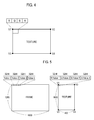
- FIG. 5 is an illustrative diagram representing an image frame and texture according to an embodiment of the present invention.
- FIGS. 6 a and 6 b are illustrative diagrams representing a location of the starting pixel of the vertex movement for each loop according to an embodiment of the present invention.
- FIGS. 7 a and 7 b are illustrative diagrams representing a direction of vertex movement according to an embodiment of the present invention.
- FIGS. 8 a , 8 b and 8 c are illustrative diagrams representing rearranged textures according to an embodiment of the present invention.
- FIGS. 9 a , 9 b , and 9 c are illustrative diagrams representing an example of multiplying the rearranged textures by filter coefficients according to an embodiment of the present invention.
- one-dimensional digital data can be represented by a one-dimensional matrix.
- FIR finite impulse response
- IIR infinite impulse response filters
- a Toeplitz matrix a matrix corresponding to FIR or IIR filter
- multiple one-dimensional digital data can be represented by a two-dimensional matrix.
- multiple one-dimensional digital data can be filtered by matrix operations between a two-dimensional matrix and a filter matrix corresponding to FIR or IIR filter.
- FIR filter (F fir ) can be represented by n ⁇ n matrix as follows:
- F fir [ h c ... h 1 0 ... 0 ⁇ ⁇ h m ⁇ ⁇ ⁇ 0 ⁇ ⁇ ⁇ ⁇ ⁇ ⁇ ⁇ 0 ⁇ ⁇ ⁇ h 1 ⁇ ⁇ ⁇ ⁇ 0 ... 0 h m ... h c ] ( 1 ) wherein n is the number of one-dimensional digital data, and h 1 to h m are FIR filter coefficients (i.e., the number of filter tabs is m).
- the present invention uses the concept of an upper shift matrix and a lower shift matrix to quickly process FIR or IIR filtering of data.
- the concept of an upper shift matrix and a lower shift matrix is explained by an exemplary 4 ⁇ 4 matrix.
- a first matrix (A), a second matrix (U) and a third matrix (D) are as follows:
- A [ 1 2 3 4 5 6 7 8 9 10 11 12 13 14 15 16 ]
- ⁇ U [ 0 1 0 0 0 0 1 0 0 0 0 1 0 0 0 0 ]
- ⁇ D [ 0 0 0 0 1 0 0 0 0 1 0 0 0 0 1 0 ] ( 2 ) wherein the first matrix (A) is a matrix of data to be filtered.
- the matrix operation between the first matrix and the second matrix, and the matrix operation between the first matrix and the third matrix are as follows:
- the elements of the first matrix are upper-shifted one step by performing the matrix operation between the first matrix and the second matrix. Further, the elements of the first matrix are lower-shifted one step by performing the matrix operation between the first matrix and the third matrix.
- the second matrix (U) and the third matrix (D) represent an upper shift matrix and a lower shift matrix, respectively.
- the elements of the first matrix are upper-shifted two steps by performing the matrix operation between the matrix UA in equation (3) and the second matrix. Further, the elements of the first matrix are lower-shifted two steps by performing the matrix operation between the matrix DA in equation (3) and the third matrix, as follows:
- n ⁇ n matrix representing FIR filter (F fir ) can be expanded as follows using the upper shift matrix and the lower shift matrix:
- IIR filter can be represented by the following equation and a Toeplitz matrix according to the degree. Thus, it can be represented by an expansion by the lower shift matrix according to the degree using the lower shift matrix (third matrix (D)).
- the matrix operation between the first matrix and the second matrix, and the matrix operation between the first matrix and the third matrix are performed as follows, then the elements of the first matrix are shifted right or left, respectively.
- the second matrix and the third matrix become a right shift matrix and a left shift matrix, respectively.
- the filter matrix of FIR or IIR filter can be effectively implemented in the GPU by expanding the matrix using the upper shift matrix and the lower shift matrix.
- An ultrasound system is described as an example image processing system according to the present invention.
- FIG. 1 is a block diagram representing an arrangement of the ultrasound system 100 according to an embodiment of the present invention.
- the ultrasound system 100 includes an input unit 110 , a data acquisition unit 120 , a processor 130 and a GPU (graphic processing unit) 140 .
- the ultrasound system 100 can further include a storage unit 150 , an image forming unit 160 , a display unit 170 and a control unit 180 .
- the input unit 110 is implemented with a control panel, a mouse, a keyboard and the like to receive setting information from a user.
- the setting information includes filter information, filter coefficient information and direction information of vertex movement.
- the filter includes FIR filter and IIR filter. A vertex and the direction of the vertex movement are described below.
- the input unit 110 can further receive the selection of the application representative of the diagnostic part of the target object, the selection of the diagnostic mode in which the ultrasound image are formed and the like.
- the data acquisition unit 120 transmits an ultrasound signal to a target object and receives the ultrasound signal reflected by the target object (i.e., an ultrasound echo signal), thereby obtaining ultrasound data.
- FIG. 2 is a block diagram representing an arrangement of the data acquisition unit 120 according to an embodiment of the present invention.
- the data acquisition unit 120 comprises a transmitting signal forming unit 121 , an ultrasound probe 122 including multiple transducer elements, a beam former 123 and an ultrasound data forming unit 124 .
- the transmitting signal forming unit 121 forms transmitting signals that will be applied to each of the multiple transducer elements of the ultrasound probe 122 considering the location and the focal points of the transducer elements of the ultrasound probe 122 .
- the transmitting signal is a signal transmitted to acquire an image frame of an ultrasound image.
- the ultrasound image includes a B-mode (brightness mode) image which shows the reflection coefficient of the ultrasound signal reflected by the target object as a two-dimensional image, a D-mode (Doppler mode) image which shows the speed of the moving target object as the Doppler spectrum using the Doppler effect, a C-mode (color mode) image which shows the speed of the moving target object and the diffusing object in color using the Doppler effect, an E-mode (elastic mode) image which shows the difference of the mechanical reactions of the medium between the case of applying stress to the target object and the case of not applying stress to the target object as an image, etc.
- B-mode blueness mode
- Doppler mode Doppler mode
- C-mode color mode
- E-mode elastic mode
- the ultrasound probe 122 is implemented as convex probe, linear probe, trapezoidal probe, IVUS (intravascular ultrasound) probe and the like, and converts the transmitting signal provided by the transmitting signal forming unit 121 into an ultrasound signal, transmits the signal to the target object, and receives the ultrasound echo signal reflected by the target object, thereby forming multiple received signals.
- the beam former 123 analog/digital converts the multiple received signals provided by the ultrasound probe 122 . Also, the beam former 123 receive-focuses the multiple digital-converted received signals considering the location and focal points of the transducer elements of the ultrasound probe 122 , thereby forming multiple receive-focused signals.
- the ultrasound data forming unit 124 forms ultrasound data corresponding to the image frame using multiple receive-focused signals provided by the beam former 123 .
- the ultrasound data includes RF (radio frequency) data and IQ (in-phase/quadrature) data.
- the processor 130 is implemented by central processing unit (CPU), field programmable gate array (FPGA), application specific integrated circuit (ASIC) and the like, thereby forming a texture in the GPU 140 according to the setting information provided by the input unit 110 , and uploading the ultrasound data to the GPU 140 .
- the GPU 140 performs the FIR or IIR filtering on the ultrasound data uploaded by the processor 130 .
- FIG. 3 is a block diagram representing the processor 130 and the GPU 140 according to an embodiment of the present invention.
- the processor 130 comprises a frame information forming unit 131 , a texture forming unit 132 , a data upload unit 133 and a texture information forming unit 134 .
- the GPU 140 comprises a video memory 141 , a vertex movement determining unit 142 , a vertex movement unit 143 and a filtering unit 144 .
- the frame information forming unit 131 forms frame information by analyzing the ultrasound data provided by the data acquisition unit 120 .
- the frame information includes first size information which comprises height and width of the image frame consisted of the ultrasound data and second size information which comprises the bit size of each pixel of the image frame.
- the texture forming unit 132 forms a texture in the video memory 141 of the GPU 140 using the frame information provided by the frame information forming unit 131 .
- the texture comprises four vertexes (V 1 to V 4 ) as described in FIG. 4 and includes multiple pixels, each of which comprises RGBA (Red, Green, Blue and Alpha) channels.
- the texture forming unit 132 can form a texture having width of 1 ⁇ 4 of the first size of the image frame as described in FIG. 5 . This is because each of the pixels of the texture comprises four channels as described in FIG. 4 . That is, the texture forming unit 132 forms a texture that has width of 1 ⁇ 4 of the width of the image frame.
- the texture forming unit 132 forms a texture that comprises four vertexes (V 1 to V 4 ) and has the size of 1600 (height) ⁇ 400 (width) and 128 bits per pixel in the video memory of the GPU 140 .
- the data upload unit 133 uploads the ultrasound data provided by the data acquisition unit 120 by 64 bits or 128 bits to the texture when the texture is formed in the video memory 141 .
- the data upload unit 133 uploads four elements of the frame data (value 1 to value 4 ) by 128 bits to each RGBA channels of one pixel of the texture as described in FIG. 5 .
- the texture information forming unit 134 forms information about the texture (referred to as texture information), to which ultrasound data are uploaded, by using the setting information provided by the input unit 110 .
- the texture information includes the size and vertex of the texture, the number of textures that can be processed in the GPU 140 at one time, the loop count, the number of pixels of the vertex movement for each loop and filter coefficients.
- the size of texture includes first size comprising the height and width of the texture and second size comprising the bit size of each pixel of the texture.
- the loop count represents the number of times to process texture according to the direction of vertex movement.
- the number of pixels of the vertex movement for each loop represents the number of times to move the vertex depending on the type of the filter (FIR or IIR filter) and the filter coefficients.
- the texture information forming unit 134 compares the number of textures that can be processed in the GPU 140 at one time (16) with the number of filter coefficients (15). If the number of textures that can be processed at one time is larger than the number of filter coefficients, then the texture information forming unit 134 sets the loop count as 1 and the number of pixels of the vertex movement as ⁇ 7 to +7.
- ⁇ 7 means moving the vertex upward or rightward by 7 pixels and +7 means moving the vertex downward or leftward by 7 pixels. That is, ⁇ 7 means multiplying the second matrix (U) 7 times, while +7 means multiplying the third matrix (D) 7 times.
- the texture information forming unit 134 forms first texture information which comprises the size (which includes the first size comprising the size of 1600 (height) ⁇ 400 (width) and the second size comprising the size of 128 bits per pixel) and the vertexes (V 1 to V 4 ) of the texture formed in the GPU 140 , the number of textures that can be processed in the GPU 140 at one time (15), loop count (1), the number of pixels of vertex movement ( ⁇ 7 to +7) and the filter coefficients (h 0 to h 14 ).
- the texture information forming unit 134 forms second texture information which comprises the size and the vertexes (V 1 to V 4 ) of the texture formed in the GPU 140 , the number of textures that can be processed in the GPU 140 at one time (16), loop count (2), the number of pixels of vertex movement for each loop (the number of pixels of vertex movement at the first loop ( ⁇ 15 to 0) and the number of pixels of vertex movement at the second loop (+1 to +16)) and the filter coefficients (h 0 to h 31 ).
- the texture information forming unit 134 forms third texture information which comprises the size and the vertexes (V 1 to V 4 ) of the texture formed in the GPU 140 , the number of textures that can be processed in the GPU 140 at one time (16), loop count (20), the number of pixels of the vertex movement for each loop (0 to +15) and the filter coefficients (k 0 to k 319 ).
- ⁇ 7 moves the vertex upward by 7 pixels and +7 moves the vertex downward by 7 pixels along the direction of the vertex movement (axial direction) in the foregoing examples
- ⁇ 7 moves the vertex downward by 7 pixels and +7 moves the vertex upward by 7 pixels in another example.
- ⁇ 7 moves the vertex leftward or rightward by 7 pixels and +7 moves the vertex rightward or leftward by 7 pixels along the direction of the vertex movement (lateral direction) in yet another example.
- the video memory 141 comprises multiple storage areas.
- a texture is formed in the video memory 141 .
- the ultrasound data uploaded by the data upload unit 133 are stored in the texture. Further, the setting information from the input unit 110 and the texture information from the texture information forming unit 134 can also be stored in the video memory 141 .
- the vertex movement determining unit 142 forms vertex movement information using the setting information provided from the input unit 110 and the texture information provided from the texture information forming unit 134 when the ultrasound data are uploaded to the texture in the video memory 141 by the data upload unit 133 .
- the vertex movement information includes the direction of the vertex movement and the location of the starting pixel of the vertex movement.
- the vertex movement determining unit 142 sets the location of the starting pixel of the vertex movement as the pixel (P 1, 1 ) with reference to the vertex (V 1 or V 2 ) as described in FIG. 6 a .
- the vertex movement determining unit 142 forms first vertex movement information comprising the direction of the vertex movement (axial direction) and the location of the starting pixel of the vertex movement (P 1, 1 ).
- the vertex movement determining unit 142 sets the location of the starting pixel of the vertex movement as the pixel (P 1, 1 ) with reference to the vertex (V 1 or V 2 ) as described in FIG. 6 a .
- the vertex movement determining unit 142 forms second vertex movement information comprising the direction of the vertex movement (axial direction) and the location of the starting pixel of the vertex movement (P 1, 1 ).
- the texture has the size of 1600 (height) ⁇ 400 (width) as described in FIG.
- the vertex movement determining unit 142 sets the location of the starting pixel of the vertex movement corresponding to the first loop as the pixel (P 1, 1 ), the location of the starting pixel of the vertex movement corresponding to the second loop as the pixel (P 17, 1 ), the location of the starting pixel of the vertex movement corresponding to the third loop as the pixel (P 33, 1 ), the location of the starting pixel of the vertex movement corresponding to the fourth loop as the pixel (P 49, 1 ), and the location of the starting pixel of the vertex movement corresponding to the fifth loop as the pixel (P 64, 1 ) with reference to the vertex (V 1 or V 2 ) as described in FIG.
- the vertex movement determining unit 142 forms third vertex movement information comprising the direction of the vertex movement (axial direction) and the location of the starting pixel of the vertex movement for each loop (P 1, 1 , P 17, 1 , P 33, 1 , P 49, 1 , P 64, 1 , . . . ).
- the vertex movement unit 143 forms the vertex location information of the texture by moving the vertex of the texture using texture information provided from the texture information forming unit 134 and the vertex movement information provided from the vertex movement determining unit 142 .
- the vertex movement unit 143 moves the vertex of the texture in the axial direction from the location of the starting pixel of the vertex movement (P 1, 1 ) as the number of pixels of the vertex movement. This forms first vertex location information as described in FIG. 8 a.
- the vertex movement unit 143 moves the vertex of the texture in the axial direction from the location of the starting pixel of the vertex movement (P 1, 1 ) as the number of pixels of the vertex movement. This forms second vertex location information as described in FIG. 8 b.
- the vertex movement unit 143 moves the vertex of the texture in the axial direction from the location of the starting pixel of the vertex movement for each loop (P 1, 1 , P 17, 1 , P 33, 1 , P 49, 1 , P 64, 1 , . . . ) as the number of pixels of the vertex movement. This forms third vertex location information as described in FIG. 8 c.
- the filtering unit 144 performs the filtering of the ultrasound data using the texture information provided from the texture information forming unit 134 and the vertex location information provided by the vertex movement unit 143 .
- the filtering unit 144 forms multiple rearranged textures by rearranging the textures using the vertex location information, multiplies each of the multiple rearranged textures by the respective filter coefficients using the texture information, and adds the rearranged textures multiplied by the filter coefficients. This performs the filtering on the ultrasound data.
- the filtering unit 144 forms 15 rearranged textures ( ⁇ 7 to +7) by rearranging the textures with reference to the location of the starting pixel of the vertex movement at the first loop (P 1, 1 ) according to the first vertex location information as described in FIG. 9 a . It then multiplies each of the 15 rearranged textures by FIR filter coefficients (h 0 to h 14 ) according to the first texture information. The filtering unit 144 performs FIR filtering on the ultrasound data by adding the 15 rearranged textures multiplied by the FIR filter coefficients.
- the filtering unit 144 forms 16 rearranged textures ( ⁇ 15 to 0) by rearranging the textures with reference to the location of the starting pixel of the vertex movement at the first loop (P 1, 1 ) according to the second vertex location information as described in FIG. 9 b . It then multiplies each of the 16 rearranged textures by the FIR filter coefficients (h 0 to h 15 ) according to the second texture information. The filtering unit 144 adds the rearranged textures multiplied by the FIR filter coefficients. In such a case, because the number of textures that can be processed in the GPU 140 at one time is 16, the filtering unit 144 temporarily stores the added texture.
- the filtering unit 144 forms 16 rearranged textures (+1 to +16) by rearranging the texture with reference to the location of the starting pixel of the vertex movement at the second loop (P 1, 1 ) according to a second vertex location information, and multiplies each of the 16 rearranged textures by the FIR filter coefficients (h 16 to h 31 ) according to the second texture information.
- the filtering unit 144 adds the added texture temporarily stored in the storage unit 150 and the rearranged textures multiplied by the FIR filter coefficients (h 16 to h 31 ), thereby performing FIR filtering on the ultrasound data.
- the filtering unit 144 forms 16 rearranged textures (0 to +15) by rearranging the textures with reference to the location of the starting pixel of the vertex movement at the first loop (P 1, 1 ) according to the third vertex location information as described in FIG. 9 c . It then multiplies each of the 16 rearranged textures by the IIR filter coefficients (k 0 to k 15 ) according to the third texture information. The filtering unit 144 adds the rearranged textures multiplied by the IIR filter coefficients. In such a case, because the number of textures that can be processed in the GPU 140 at one time is 16, the filtering unit 144 temporarily stores the added texture.
- the filtering unit 144 forms 16 rearranged textures (0 to +15) by rearranging the textures with reference to the location of the starting pixel of the vertex movement at the second loop (P 17, 1 ) according to the third vertex location information, and multiplies each of the 16 rearranged textures by the IIR filter coefficients (k 16 to k 31 ) according to the third texture information.
- the filtering unit 144 adds the added textured temporarily stored in the storage unit 150 and the rearranged textures multiplied by the IIR filter coefficients.
- the filtering unit 144 performs the above procedure as many times as the loop count, thereby performing IIR filtering on the ultrasound data.
- the storage unit 150 temporarily stores the texture added in the filtering unit 144 .
- the added texture can be stored in the storage area of the video memory 141 in another embodiment.
- the image forming unit 160 forms an ultrasound image using the ultrasound data filtered in the GPU 140 .
- the display unit 170 displays the ultrasound image formed in the image forming unit 160 .
- the controlling unit 180 controls the acquisition of the ultrasound data. Moreover, the controlling unit 180 controls the forming of the texture and the uploading of the ultrasound data. It further controls the processing of the texture and the filtering of the ultrasound data.
Abstract
Description
wherein n is the number of one-dimensional digital data, and h1 to hm are FIR filter coefficients (i.e., the number of filter tabs is m). Here, c=m/2 wherein m=even, and c=(m+1)/2 wherein m=odd.
wherein the first matrix (A) is a matrix of data to be filtered.
wherein the exponential parts of the second matrix and the third matrix represent the shift steps of the elements of the first matrix (i.e., the number of times the second matrix or the third matrix is multiplied).
Claims (10)
Applications Claiming Priority (2)
| Application Number | Priority Date | Filing Date | Title |
|---|---|---|---|
| KR10-2008-0127404 | 2008-12-15 | ||
| KR20080127404 | 2008-12-15 |
Publications (2)
| Publication Number | Publication Date |
|---|---|
| US20100149198A1 US20100149198A1 (en) | 2010-06-17 |
| US8446419B2 true US8446419B2 (en) | 2013-05-21 |
Family
ID=41829215
Family Applications (1)
| Application Number | Title | Priority Date | Filing Date |
|---|---|---|---|
| US12/637,577 Expired - Fee Related US8446419B2 (en) | 2008-12-15 | 2009-12-14 | Image processing system and method |
Country Status (4)
| Country | Link |
|---|---|
| US (1) | US8446419B2 (en) |
| EP (1) | EP2199971A1 (en) |
| JP (1) | JP2010140489A (en) |
| KR (1) | KR101083939B1 (en) |
Families Citing this family (4)
| Publication number | Priority date | Publication date | Assignee | Title |
|---|---|---|---|---|
| US8698659B2 (en) * | 2012-07-23 | 2014-04-15 | Tektronix, Inc. | Time interleaved analog to digital converter mismatch correction |
| WO2016159417A1 (en) * | 2015-04-02 | 2016-10-06 | 알피니언메디칼시스템 주식회사 | Image processing device and method removing afterimage of ultrasonic image |
| CN106805997B (en) * | 2016-12-26 | 2020-08-07 | 乐普(北京)医疗器械股份有限公司 | Elastic imaging method and device |
| CN110378203B (en) * | 2019-06-05 | 2023-06-23 | 平安科技(深圳)有限公司 | Image processing method, device, terminal and storage medium |
Citations (4)
| Publication number | Priority date | Publication date | Assignee | Title |
|---|---|---|---|---|
| US20030097068A1 (en) * | 1998-06-02 | 2003-05-22 | Acuson Corporation | Medical diagnostic ultrasound system and method for versatile processing |
| JP2004105638A (en) | 2002-09-20 | 2004-04-08 | Shimadzu Corp | Ultrasonic diagnostic apparatus |
| US20050251008A1 (en) | 2004-04-26 | 2005-11-10 | Lihong Pan | System and method for filtering in imaging systems |
| US20080161690A1 (en) | 2006-12-27 | 2008-07-03 | Kabushiki Kaisha Toshiba | Ultrasonic imaging apparatus and a method for displaying diagnostic images |
-
2009
- 2009-12-02 EP EP20090177800 patent/EP2199971A1/en not_active Withdrawn
- 2009-12-03 KR KR1020090118874A patent/KR101083939B1/en active IP Right Grant
- 2009-12-14 US US12/637,577 patent/US8446419B2/en not_active Expired - Fee Related
- 2009-12-14 JP JP2009283037A patent/JP2010140489A/en active Pending
Patent Citations (5)
| Publication number | Priority date | Publication date | Assignee | Title |
|---|---|---|---|---|
| US20030097068A1 (en) * | 1998-06-02 | 2003-05-22 | Acuson Corporation | Medical diagnostic ultrasound system and method for versatile processing |
| JP2004105638A (en) | 2002-09-20 | 2004-04-08 | Shimadzu Corp | Ultrasonic diagnostic apparatus |
| US20050251008A1 (en) | 2004-04-26 | 2005-11-10 | Lihong Pan | System and method for filtering in imaging systems |
| US20080161690A1 (en) | 2006-12-27 | 2008-07-03 | Kabushiki Kaisha Toshiba | Ultrasonic imaging apparatus and a method for displaying diagnostic images |
| JP2008161289A (en) | 2006-12-27 | 2008-07-17 | Toshiba Corp | Ultrasonic diagnostic apparatus |
Non-Patent Citations (12)
| Title |
|---|
| Devey, G. B., et al., "Ultrasound in Medical Diagnosis", Scientific American, vol. 238, May 1978, pp. 98-112. |
| European Office Action issued in European Patent Application No. 09 177 800.1 dated May 16, 2012. |
| European Office Action, issued in European Patent Application No. 09177800.1, dated Jul. 20, 2011. |
| European Search Report for Application No. 09177800.1-2218, mailed Mar. 31, 2010, 7 pages. |
| Fatahalian et al., Understanding the Efficiency of GPU Algorithms for Matrix-Matrix Multiplication, Graphics Hardware, The Eurographics Association, pp. 133-137 (2004). |
| Hopf et al., Accelerating 3D Convolution using Graphics Hardware, 0-7803-5897-X/99 IEEE, pp. 471-474 (1999). |
| Kass M., Lefohn A., Owens J.: Interactive Depth of Field. Tech. Rep. #06-01, Pixar. Available at http://graphics.pixar.com/DepthOfField/, 2006. * |
| Korean Office Action issued in Korean Patent Application No. KR 10-2009-0118874 dated Oct. 26, 2011. |
| Larsen et al., Fast Matrix Multiplies using Graphics Hardware, Proceedings of the ACM/IEEE SC2001 Conference (SC01) 1-58113-293-X/01, 6 pages (2001). |
| Owens et al., A Survey of General-Purpose Computation on Graphics Hardware, Computer Graphics forum, vol. 26, No. 1, 2007 The Authors, Journal compilation, pp. 80-113 (2007). |
| Smirnov et al., An Implementation of a FIR Filter on a GPU, Technical Report ECSI, pp. 1-8 (2005). |
| Tay, David B. H., et al., "Structures for Multidimensional FIR Perfect Reconstruction Filter Banks", Speech Processing 1. San Francisco, Mar. 23-26, 1991; Proceedings of the International Conference on Acoustics, Speech, and Signal Processing (ICASSP), vol. 4, Mar. 23, 1992, pp. IV-641-IV-644. |
Also Published As
| Publication number | Publication date |
|---|---|
| KR101083939B1 (en) | 2011-11-15 |
| EP2199971A1 (en) | 2010-06-23 |
| KR20100069577A (en) | 2010-06-24 |
| JP2010140489A (en) | 2010-06-24 |
| US20100149198A1 (en) | 2010-06-17 |
Similar Documents
| Publication | Publication Date | Title |
|---|---|---|
| US20090099451A1 (en) | Ultrasonic imaging apparatus and a method for generating an ultrasonic image | |
| US8684934B2 (en) | Adaptively performing clutter filtering in an ultrasound system | |
| EP1990009B1 (en) | Ultrasonic diagnostic equipment | |
| US20100010344A1 (en) | Enhanced Ultrasound Data Processing in an Ultrasound System | |
| US9354313B2 (en) | Ultrasound diagnostic apparatus and method for acquiring ultrasound data | |
| US8446419B2 (en) | Image processing system and method | |
| US20170188998A1 (en) | Providing user interface in ultrasound system | |
| US20200281570A1 (en) | Apparatus | |
| CN105122299A (en) | Ultrasound image displaying apparatus and method for displaying ultrasound image | |
| US20100130861A1 (en) | Ultrasonic diagnostic apparatus and program | |
| JP6997508B2 (en) | Ultrasonic diagnostic equipment and its control program | |
| US20100113931A1 (en) | Ultrasound System And Method For Providing Three-Dimensional Ultrasound Images | |
| US20190125310A1 (en) | Ultrasound diagnostic apparatus, ultrasound image generation method and storage medium | |
| US20120123266A1 (en) | Ultrasound system and method for providing preview image | |
| JP2012120840A (en) | Ultrasonic system for providing additional information to indicate temporal change in blood flow, and method | |
| JP2021159276A (en) | Ultrasonic diagnostic apparatus | |
| KR100971434B1 (en) | Ultrasound system and method for processing ultrasound data | |
| US20070197910A1 (en) | Apparatus and method for displaying an ultrasound image | |
| JP5656389B2 (en) | Ultrasound system for adaptive persistence processing of elastic images | |
| JP6488771B2 (en) | Ultrasonic diagnostic equipment | |
| JP6722322B1 (en) | Ultrasonic device and its control program | |
| US11690598B2 (en) | Ultrasound diagnostic apparatus and non-transitory storage medium | |
| JP4976231B2 (en) | Ultrasonic diagnostic equipment | |
| US8098913B2 (en) | Ultrasonic diagnostic apparatus and image filtering method of the same | |
| JP7159361B2 (en) | Ultrasound image display system and its control program |
Legal Events
| Date | Code | Title | Description |
|---|---|---|---|
| AS | Assignment |
Owner name: MEDISON CO., LTD.,KOREA, REPUBLIC OF Free format text: ASSIGNMENT OF ASSIGNORS INTEREST;ASSIGNORS:AHN, CHI YOUNG;LEE, SUK JIN;REEL/FRAME:023651/0811 Effective date: 20091130 Owner name: MEDISON CO., LTD., KOREA, REPUBLIC OF Free format text: ASSIGNMENT OF ASSIGNORS INTEREST;ASSIGNORS:AHN, CHI YOUNG;LEE, SUK JIN;REEL/FRAME:023651/0811 Effective date: 20091130 |
|
| FEPP | Fee payment procedure |
Free format text: PAYOR NUMBER ASSIGNED (ORIGINAL EVENT CODE: ASPN); ENTITY STATUS OF PATENT OWNER: LARGE ENTITY |
|
| STCF | Information on status: patent grant |
Free format text: PATENTED CASE |
|
| AS | Assignment |
Owner name: SAMSUNG MEDISON CO., LTD., KOREA, REPUBLIC OF Free format text: CHANGE OF NAME;ASSIGNOR:MEDISON CO., LTD.;REEL/FRAME:032874/0741 Effective date: 20110329 |
|
| FPAY | Fee payment |
Year of fee payment: 4 |
|
| FEPP | Fee payment procedure |
Free format text: MAINTENANCE FEE REMINDER MAILED (ORIGINAL EVENT CODE: REM.); ENTITY STATUS OF PATENT OWNER: LARGE ENTITY |
|
| LAPS | Lapse for failure to pay maintenance fees |
Free format text: PATENT EXPIRED FOR FAILURE TO PAY MAINTENANCE FEES (ORIGINAL EVENT CODE: EXP.); ENTITY STATUS OF PATENT OWNER: LARGE ENTITY |
|
| STCH | Information on status: patent discontinuation |
Free format text: PATENT EXPIRED DUE TO NONPAYMENT OF MAINTENANCE FEES UNDER 37 CFR 1.362 |
|
| FP | Lapsed due to failure to pay maintenance fee |
Effective date: 20210521 |