US8441220B2 - Control device for electric rotating machine - Google Patents
Control device for electric rotating machine Download PDFInfo
- Publication number
- US8441220B2 US8441220B2 US13/238,309 US201113238309A US8441220B2 US 8441220 B2 US8441220 B2 US 8441220B2 US 201113238309 A US201113238309 A US 201113238309A US 8441220 B2 US8441220 B2 US 8441220B2
- Authority
- US
- United States
- Prior art keywords
- operating state
- current
- value
- controlled variable
- control
- Prior art date
- Legal status (The legal status is an assumption and is not a legal conclusion. Google has not performed a legal analysis and makes no representation as to the accuracy of the status listed.)
- Expired - Fee Related, expires
Links
- 230000008859 change Effects 0.000 claims abstract description 48
- 241000153282 Theope Species 0.000 claims 1
- 239000013598 vector Substances 0.000 description 294
- 230000004907 flux Effects 0.000 description 35
- 238000000034 method Methods 0.000 description 26
- 230000007704 transition Effects 0.000 description 9
- 238000001514 detection method Methods 0.000 description 8
- 238000004804 winding Methods 0.000 description 7
- 230000008569 process Effects 0.000 description 6
- 230000004044 response Effects 0.000 description 6
- 230000000052 comparative effect Effects 0.000 description 5
- 230000001360 synchronised effect Effects 0.000 description 5
- 238000006243 chemical reaction Methods 0.000 description 4
- 230000006698 induction Effects 0.000 description 2
- 230000008901 benefit Effects 0.000 description 1
- 230000003111 delayed effect Effects 0.000 description 1
- 230000000694 effects Effects 0.000 description 1
- 238000001914 filtration Methods 0.000 description 1
- 239000000446 fuel Substances 0.000 description 1
- 238000004519 manufacturing process Methods 0.000 description 1
- 238000012986 modification Methods 0.000 description 1
- 230000004048 modification Effects 0.000 description 1
- 230000009467 reduction Effects 0.000 description 1
Images
Classifications
-
- H—ELECTRICITY
- H02—GENERATION; CONVERSION OR DISTRIBUTION OF ELECTRIC POWER
- H02P—CONTROL OR REGULATION OF ELECTRIC MOTORS, ELECTRIC GENERATORS OR DYNAMO-ELECTRIC CONVERTERS; CONTROLLING TRANSFORMERS, REACTORS OR CHOKE COILS
- H02P21/00—Arrangements or methods for the control of electric machines by vector control, e.g. by control of field orientation
- H02P21/13—Observer control, e.g. using Luenberger observers or Kalman filters
-
- H—ELECTRICITY
- H02—GENERATION; CONVERSION OR DISTRIBUTION OF ELECTRIC POWER
- H02P—CONTROL OR REGULATION OF ELECTRIC MOTORS, ELECTRIC GENERATORS OR DYNAMO-ELECTRIC CONVERTERS; CONTROLLING TRANSFORMERS, REACTORS OR CHOKE COILS
- H02P21/00—Arrangements or methods for the control of electric machines by vector control, e.g. by control of field orientation
- H02P21/0003—Control strategies in general, e.g. linear type, e.g. P, PI, PID, using robust control
- H02P21/0017—Model reference adaptation, e.g. MRAS or MRAC, useful for control or parameter estimation
Definitions
- the present invention relates generally to a control device which controls switching elements of an electric power inverter circuit having connecting points, being connected with respective terminals of an electric rotating machine and being set at respective electric potentials different from one another, by changing an on (i.e., conductive) or off (i.e., non-conductive) state of selected switching elements to the off or on state and which controls a controlled variable of the electric rotating machine connected with the connecting points of the electric power inverter circuit.
- the present invention relates more particularly to the control device which has a predicting unit that performs a prediction for the controlled variable of the electric rotating machine, on the assumption that the electric power inverter circuit is set in one of operating states to set the switching elements instates corresponding to the operating state, an operating state determining unit that determines one of the operating states of the electric power inverter circuit by using the predicted controlled variable and an instructed value of the controlled variable, and a control unit that controls the electric power inverter circuit to actually set the electric power inverter circuit in the determined operating state.
- a control method for a three-phase motor receiving driving power through an inverter has been used.
- an operating state of the inverter is repeatedly switched or changed to another state to adjust an alternating current supplied to the motor and to control the motor.
- a model predict ion control using a motor driving system has been proposed in Published Japanese Patent First Publication No. 2008-228419.
- an alternating current flowing through a three-phase motor is predicted each time an inverter is set in one of various operating states, and the inverter is controlled to be set in an appropriate operating state in which a difference between the predicted current and an instructed current can be minimized.
- the value of the predicted current is predicted by using a detected value of an alternating current actually flowing through the motor as an initial value.
- the inverter is controlled so as to optimize a change in the current predicted based on an output voltage of the inverter. Therefore, in a transition period of time until the value of the instructed current becomes constant, the current outputted from the inverter can preferably follow the instructed current. Accordingly, the model prediction control can be useful for a control device of a motor generator requiring a high follow-up performance in a transition period as an on-board primary component.
- a predicting period is required to perform the calculation for predicting the alternating current of the motor, and the precision in the control performed for the motor can be heightened when the changing period of the operating state is shortened. Therefore, when the detection of an alternating current flowing through the motor is stopped until ringing generated in the current disappears, it is difficult to perform the model prediction control at a high controllability for a three-phase motor.
- An object of the present invention is to provide, with due consideration to the drawbacks of the conventional control method using a motor driving device or system, a control device which controls an electric rotating machine, receiving electric power through an electric power inverter circuit, at a high controllability for the rotating machine according to the model prediction control while suppressing the lowering of the controllability caused by a change of an operating state of the inverter circuit.
- the object is achieved by the provision of a control device for controlling a plurality of switching elements of an electric power inverter circuit having a plurality of connecting points, which are connected with respective terminals of an electric rotating machine and are set at respective electric potentials different from one another, by selecting one switching element or more from the switching elements and by changing states of the selected switching elements and for controlling a control led variable of the electric rotating machine.
- the control device comprises a predicting unit that performs a prediction for the controlled variable of the electric rotating machine when the electric power inverter circuit is set in one of a plurality of operating states to set the switching elements in states corresponding to the operating state, an operating state determining unit that determines one of the operating states of the electric power inverter circuit as a determined operating state by using the predicted controlled variable and an instructed value of the controlled variable, and a control unit that controls the electric power inverter circuit to actually set the electric power inverter circuit in the determined operating state.
- the predicting unit sets a value of the controlled variable, actually detected from the electric rotating machine, or a value of a physical quantity, from which the value of the control variable can be obtained and which is actually detected from the electric rotating machine, as an initial value to predict a first value of the controlled variable or the physical quantity on the basis of the initial value as an input parameter in the operating state determination of the operating state determining unit.
- the predicting unit predicts the first value of the controlled variable or the physical quantity as the input parameter in a predetermined period of time, starting at a time when one operating state set in the electric power inverter circuit is changed to another operating state, by using a second value of the control led variable or the physical quantity, which has been predicted based on a value of the controlled variable or the physical quantity detected before the change of the operating state set in the electric power inverter circuit, as the initial value.
- the controlled variable or the physical quantity can be predicted without being influenced by the ringing, the precision in the prediction can be heightened, and the controllability of the control device for the electric rotating machine can be heightened.
- FIG. 1 is a view showing the structure of a control system having a control device according to the first embodiment of the present invention
- FIG. 2A shows eight voltage vectors corresponding to eight operating states of an inverter shown in FIG. 1 ;
- FIG. 2B shows directions and magnitudes of the voltage vectors
- FIG. 3 shows a transition of the operating state preferentially selected in a model prediction control according to the first embodiment
- FIG. 4 is a flow chart showing the processing in the model prediction control according to the first embodiment
- FIG. 5 is a flow chart showing the processing for predicting a current vector in the model prediction control shown in FIG. 4 :
- FIG. 6 is a flow chart showing the processing for examining the replacement of a voltage vector in the model prediction control shown in FIG. 4 :
- FIG. 7 is a flow chart showing the processing for obtaining a current to be used as an initial value for the current prediction
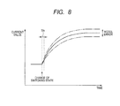
- FIG. 8 is a time chart exemplarily showing the relation between a response time of current and a prohibiting period
- FIG. 9A is a time chart showing a transition of a voltage vector with a change of a phase current and an SW change flag according to a comparative prior art
- FIG. 9B is a time chart showing a transition of a voltage vector with a change of a phase current and an SW change flag according to the first embodiment.
- FIG. 10 is a view showing the structure of a control system having a control device according to the second embodiment of the present invention.
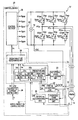
- FIG. 1 is a view showing the structure of a control system having a control device for an electric rotating machine according to the first embodiment.
- a control system has a high voltage battery 12 outputting electric power of a high direct current (dc) voltage as a direct current power source, an inverter IV set in one of various operating states to convert the power of the battery 12 into electric power of a three-phase alternating current (ac) voltage corresponding to the operating state, a motor generator 10 receiving the power through the inverter IV as an electric rotating machine to generate a torque (or a rotational force), and a control device 20 for receiving a target torque Tr, receiving detection values from various sensors detecting specific controlled variables of the motor generator 10 or physical values by which values of the specific controlled variables can be calculated, and adjusting a change of the operating state of the inverter IV according to the target torque Tr and the detection values of the specific controlled variables to control controlled variables of the motor generator 10 such that the motor generator 10 appropriately generates a torque matching with the target torque Tr.
- dc direct current
- the motor generator 10 is a three-phase interior permanent magnet synchronous motor (IPMSM).
- IPMSM three-phase interior permanent magnet synchronous motor
- This generator 10 has a rotor, permanent magnets having salient poles and being disposed around a shaft of the rotor so as to be protruded from the shaft, a stator surrounding the rotor, and three windings (i.e., a U phase winding, a V phase winding and a W phase winding) wound on the stator.
- the generator 10 is an on-boarded primary component of a vehicle, and the shaft of the generator 10 is mechanically connected with driving wheels of the vehicle to rotate the wheels by using the generated torque.
- Three terminals of the generator 10 are connected with the battery 12 through the inverter IV.
- the inverter IV has a plurality of switching elements and a plurality of connecting points Pcu, PCv and PCw which are connected with the respective terminals of the generator 10 and are set at respective electric potentials different from one another by the switching elements.
- the switching elements are arranged so as to be able to connect each of the terminals of the generator 10 with any of a positive electrode and a negative electrode of the battery 12 .
- the control device 20 selects two switching elements or more from the switching elements and changes the state of each selected switching element to another one to control phase currents (i.e., controlled variables) flowing through the terminals of the generator 10 .
- the inverter IV has U phase switching elements ESup and ESun serially connected with each other at a U phase connecting point Pcu as a U phase serial connection member, V phase switching elements ESvp and ESvn serially connected with each other at a V phase connecting point PCv as a V phase serial connection member, and W phase switching elements ESwp and Swn serially connected with each other at a W phase connecting point PCw as a W phase serial connection member.
- Emitters of the switching elements ESup, ESvp and ESwp are connected with collectors of the respective switching elements ESun, ESvn and ESwn.
- Each of the switching elements ESup, Esvp, Esvn, ESwp and Swn is made of an n-p-n insulated-gate bipolar transistor (IGBT).
- the inverter IV further has a plurality of diodes Dup, Dun, Dvp, Dvn, Dwp and Dwn connected with the respective switching elements ESup, Esun, Esvp, Esvn, ESwp and Swn in parallel.
- the anode of each diode is connected with the emitter of the corresponding switching element. Therefore, the direct ion of a current allowed to flow through each diode is opposite to the direction of a current possible to flow through the corresponding switching element.
- Each diode acts as a freewheel diode.
- the control device 20 constitutes a low voltage system. More specifically, although the inverter IV and the motor generator 10 are ope rated by using electric power of a high voltage, the control device 20 is operated by using electric power of a low voltage.
- the control system further has various sensors such as a voltage sensor 18 for detecting a supply voltage VDC of the battery 12 applied to the inverter IV, a current sensor 16 for detecting phase currents Iu, Iv and Iw flowing through the terminals of the generator 10 , and a rotational angle sensor 14 for detecting a rotational angle ⁇ of the rotor of the generator 10 .
- the control device 20 receives detected values of these sensors 14 , 16 and 18 through an interface (not shown).
- the control device 20 produces control signals Sgup, Sgun, Sgvp, Sgvn, Sgwp and Sgwn every control period Tc according to the received detected values and the target torque Tr and transmits the signals Sgup, Sgun, Sgvp, Sgvn, Sgwp and Sgwn to bases of the respective switching elements ESup, Esun, Esvp, Esvn, ESwp and Eswn of the inverter IV.
- the inverter IV converts the power of the supply voltage VDC into the power of a controlled voltage Vc according to the control signals every control period Tc.
- the control device 20 controls the switching elements of the inverter IV to changeably connect each terminal of the generator 10 with the positive or negative electrode of the battery 12 .
- the control device 20 performs a control of controlled variables of the generator 10 according to a model prediction method and performs a method of obtaining an initial value for the prediction of the controlled variables in the control of the controlled variables.
- the control device 20 operates the inverter IV to indirectly control a torque actually produced in the generator 10 to the target torque Tr. More specifically, the device 20 operates the inverter IV to directly control the alternating current, actually flowing through the generator 10 , to an instructed current. This instructed current is required for the generator 10 to generate the target torque Tr. That is, in this embodiment, although the device 20 controls the torque generated in the generator 10 as a final controlled variable, the device 20 directly controls a current, actually flowing through the generator 10 , to the instructed current to control the torque generated in the generator 10 .
- the inverter IV can be set in any of a plurality of operating states. Each operating state corresponds to a pattern of on and off states of the switching elements ESup, Esun, Esvp, Esvn, ESwp and Eswn of the inverter IV.
- a voltage vector of the controlled voltage Vc applied from the inverter IV to the generator 10 depends on the operating state set in the inverter IV. To control the current (i.e.
- the device 20 predicts a current (i.e., a controlled variable) flowing through the generator 10 from the detected value (i.e., an input parameter) of the sensor 16 , the detected values of the sensors 14 and 18 and the instructed current (i.e., an input parameter), and determines an operating state to be actually set in the inverter IV on the basis of a difference between the predicted current and the instructed current.
- a current i.e., a controlled variable
- This control is called a model prediction control in this specification.
- the control device 20 has a first dq converting unit 22 for converting phase currents Iu, Iv and Iw detected in the sensor 16 into an actual current Idqa composed of an actual d-axis current Ida and an actual q-axis current Iqa defined on a dq rotational coordinate system by using the rotational angle ⁇ of the sensor 14 , a rotational speed calculating unit 23 for performing a differential calculation for a rotational angle ⁇ detected in the sensor 14 with respect to time to obtain an electrical angle rotational speed ⁇ of the rotor of the generator 10 , and an instructed current setting unit 24 for setting an instructed current Idqr composed of an instructed d-axis current Idr and an instructed q-axis current Iqr corresponding to the target torque Tr on the dq rotational coordinate system such that a maximum torque can be generated from a minimum current in the generator 10 .
- the control device 20 further has a model prediction control section 30 for determining a specific voltage vector Vs, corresponding to a specific operating state of the inverter IV, as a next voltage vector of a next control period every control period Tc from input parameters such as the actual currents Id and Iq, the instructed currents Idr and Iqr, the rotational speed ⁇ , the rotational angle ⁇ and the supply voltage VDC, and a control section 26 for producing control signals Sgup, Sgun, Sgvp, Sgvn, Sgwp and Sgwn from the voltage vector Vs determined by the section 30 every control period Tc and supplying the control signals to the inverter IV such that the inverter IV is set in the specific operating state corresponding to the voltage vector Vs and outputs the controlled voltage Vc to the generator 10 .
- a model prediction control section 30 for determining a specific voltage vector Vs, corresponding to a specific operating state of the inverter IV, as a next voltage vector of a next control period every control period T
- the dq rotational coordinate system is rotated with the rotor of the generator 10 .
- the d-axis of the coordinate system is set so as to be directed from one S magnetic pole to the corresponding N magnetic pole in the rotor.
- the q-axis of the coordinate system is set to be orthogonal to the d-axis on a plane perpendicular to the rotation axis of the rotor. The original point of this system is placed on the rotation axis of the rotor.
- the alternating current (i.e., phase currents) of the generator 10 is set as a controlled variable. Because the control device 20 controls the generator 10 such that the phase currents Iu, Iv and Iw of the generator 10 is adjusted to the instructed current Idqr, the controlled variable is directly controlled.
- phase currents Iu, Iv and Iw detected in the sensor 16 are converted into an actual d-axis current Ida and an actual q-axis current Iqa in the unit 22 , a rotational speed ⁇ of the rotor of the generator 10 is obtained from a rotational angle ⁇ detected in the sensor 14 in the unit 23 , and an instructed d-axis current Idr and an instructed q-axis current Iqr corresponding to the target torque Tr is set in the unit 24 so as to generate a maximum torque from a minimum current in the generator 10 .
- a specific voltage vector Vs is determined from the actual currents Id and Iq, the instructed currents Idr and Iqr, the rotational speed ⁇ , the rotational angle ⁇ and the supply voltage VDC.
- control signals Sgup, Sgun, Sgvp, Sgvn, Sgwp and Sgwn are produced from the voltage vector Vs and are supplied to the inverter IV. Therefore, the inverter IV is set in the operating state corresponding to the specific voltage vector Vs, and the inverter IV applies the controlled voltage Vc to the generator 10 .
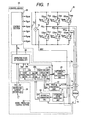
- FIG. 2A shows eight voltage vectors corresponding to eight operating states of the inverter IV
- FIG. 2B shows directions and magnitudes of the voltage vectors.
- the control voltage Vc has the voltage vector V 0 .
- the controlled voltage Vc has the voltage vector V 7 .
- the voltage vectors V 0 and V 7 all phases of the generator 10 are short-circuited, so that the controlled voltage Vc is set at zero. Therefore, each of the voltage vectors V 0 and V 7 is called a zero voltage vector.
- the voltage vectors V 1 to V 6 at least one of the switching elements Esun, Esvn and Eswn and at least one of the switching elements Esup, Esvp and Eswp are set in the on state, so that the controlled voltage Vc has magnitudes larger than zero. Therefore, each of the voltage vectors V 1 to V 6 is called an effective voltage vector.
- a switching state of the U phase is determined by a pattern of states of the switching elements Esup and Esun
- a switching state of the V phase is determined by a pattern of states of the switching elements Esvp and Esvn
- a switching state of the W phase is determined by a pattern of states of the switching elements Eswp and Eswn.
- the effective voltage vectors V 1 to V 6 are expressed on the fixed two-dimensional coordinate system while placing the zero voltage vectors V 0 and V 7 at the original point of this coordinate system.
- the voltage vector V 1 obtained by setting only the switching element Esup in the on state is directed toward the U phase and has a positive value
- the voltage vector V 3 obtained by setting only the switching element Esvp in the on state is directed toward the V phase and has a positive value
- the voltage vector V 5 obtained by setting only the switching element Eswp in the on state is directed toward the W phase and has a positive value.
- control section 30 The operation basically performed in the control section 30 will be described in detail.
- the control section 30 has an operating state producing unit 31 for producing the voltage vectors V 0 to V 7 from the value of the supply voltage VDC and outputting the voltage vectors V 0 to V 7 , corresponding to respective operating states of the inverter IV, one after another every control period Tc.
- Each voltage vector is defined on the UVW phases coordinate system.
- a phase component of the voltage vector is expressed by the value VDC/2 when the corresponding switching element Esup, Esvp or Eswp is set in the on state, while the phase component of the voltage vector is expressed by the value ⁇ VDC/2 when the corresponding switching element Esun, Esvn or Eswn is set in the on state.
- the voltage vector V 0 is expressed by ( ⁇ VDC/2, ⁇ VDC/2, ⁇ VDC/2)
- the voltage vector V 1 is expressed by (VDC/2, ⁇ VDC/2, ⁇ VDC/2).
- the control section 30 further has a second dq converting unit 32 for converting each of the voltage vectors V 0 to V 7 produced in the producing unit 31 into a voltage vector (Vd, Vq) of the controlled voltage Vc, defined on the dq rotational coordinate system, by using the rotational angle ⁇ .
- the control section 30 further has a predicting unit 33 with a current selecting block 33 a , a second predicting block 33 b and a first predicting block 33 c .
- the second predicting block 33 b predicts an alternating current Idqe(n+1), composed of a d-axis current Ide(n+1) and a q-axis current Iqe(n+1) of the next control period Tc(n+1), in the present control period Tc(n) every control period Tc.
- the selecting unit 33 a receives the actual current Idqa(Ida, Iqa) from the converting unit 22 and receives the predicted current from the second predicting block 33 b every control period Tc.
- the selecting unit 33 a selects the actual current Idqa as a voltage determining current Idq composed of voltage determining current components Id and Iq.
- the selecting unit 33 a selects an alternating current Idqe(n) composed of a d-axis current Ide(n) and a q-axis current Iqe(n), already predicted in the second predicting block 33 b in the preceding control period Tc(n ⁇ 1), as a voltage determining current Idq composed of voltage determining current components Id and Iq.
- the role of the selecting unit 33 a in the control device 20 will be described later in detail.
- the predicting unit 33 predicts an alternating current Idqe of a first control period, on the assumption that the inverter IV is set in one operating state corresponding to one voltage vector produced in the producing unit 31 , in a second control period earlier than the first control period by the time length of one control period by using the voltage vector (Vd, Vq) of the converting unit 32 , the current Idq (Id, Iq) of the selecting block 33 a , and the rotational speed ⁇ of the calculating unit 23 each time the selecting unit 32 selects one of the voltage vectors.
- Vd ( R+pLd ) Id ⁇ Lq ⁇ Iq (c1)
- Vq ⁇ Ld ⁇ Id+ ( R+pLq ) Iq+ ⁇ (c2)
- the variables Vd and Vq denote a d-axis voltage component and a q-axis voltage component of the controlled voltage Vc applied to the generator 10
- the variables Id and Iq denote a d-axis current and a q-axis current actually flowing through the generator 10
- the parameter R denotes the resistance of the armature winding
- the parameters Ld and Lq denote the d-axis inductance and the q-axis inductance
- the parameter ⁇ is a constant of armature winding linkage magnetic fluxes.
- a differential operator p i.e., d/dt
- a differential equation (c3) expressing a differential term pId of the d-axis current Id is obtained as a state equation by rearranging the terms of the equation (c1)
- a differential equation (c4) expressing a differential term p Iq of the q-axis current Iq is obtained as a state equation by rearranging the terms of the equation (c1).
- pID ⁇ ( R/Ld ) Id+ ⁇ ( Lq/Ld ) Iq+Vd/Ld (c3)
- pIq ⁇ ( Ld/Lq ) Id ⁇ ( R/Lq ) Iq+Vq/Lq ⁇ /Lq (c4)
- the predicting unit 33 predicts currents Ide and Iqe for each of the voltage vectors V 0 to V 7 determined in the unit 31 every control period Tc.
- the control section 30 further has an operating state determining unit 34 for determining a level of estimation based on an estimating function J for each of the voltage vectors V 0 to V 7 produced in the producing unit 31 and determining one voltage vector corresponding to the highest level of estimation as an optimum voltage vector Vs corresponding to an optimum operating state, to be actually set in the inverter IV, every control period Tc.
- an operating state determining unit 34 for determining a level of estimation based on an estimating function J for each of the voltage vectors V 0 to V 7 produced in the producing unit 31 and determining one voltage vector corresponding to the highest level of estimation as an optimum voltage vector Vs corresponding to an optimum operating state, to be actually set in the inverter IV, every control period Tc.
- the squared magnitude is always positive. In this case, the value of the function J can be increased with the difference between the vectors Idqr and Idqe.
- the estimation level is lowered with the increase of the value of the function J.
- the function J can be defined such that the estimation level is lowered with the increase of the difference in each component between the vectors Idqr and Idqe. Therefore, when the value of the function J for one voltage vector produced in the producing unit 31 is minimized among values of the function J for the voltage vectors V 0 to V 7 , the determining unit 34 determines this voltage vector of the minimized value as an optimum voltage vector Vs corresponding to an optimum operating state to be set in the inverter IV.
- the control device 20 can select the optimum operating state of the inverter IV so as to minimize the difference between the instructed current vector Idqr and the predicted current vector Idqe. This determination is performed every control period Tc. However, because the optimum operating state is determined in a local time scale corresponding to one control period Tc, the changing frequency of switching states corresponding to respective phases is sometimes increased. The switching state of each phase indicates a pattern of on or off states set in two switching elements of the phase in the inverter IV. The increase of the changing frequency causes ringing in the phase currents flowing through the generator 10 at a high frequency. In this case, controllability of the control device 20 for the switching elements of the inverter IV and the generator 10 is sometimes lowered.
- the control device 20 selects the optimum operating state every control period Tc while referring to or using an average voltage vector Va.
- the average voltage vector Va denotes a voltage only having a fundamental wave component of the controlled voltage Vc outputted from the inverter IV, and this fundamental wave component has an electrical angle frequency.
- a controlled voltage Vc imitating a voltage which has a component of the electrical angle frequency and has a sinusoidal wave shape, is obtained in the inverter IV.
- the voltage having the imitated sinusoidal wave shape is the average voltage vector Va.
- the norm of the average voltage vector Va is a physical value which is proportional to a modulation factor expressed by percentage or a voltage utilization factor.
- the modulation factor denotes a Fourier coefficient of the fundamental wave component contained in the controlled voltage Vc. When this Fourier coefficient is calculated, the amplitude center of the fundamental wave component is set to be equal to the central value in the changing width of the controlled voltage Vc.
- the inventor of this application found out that the average voltage vector Va is appropriate to control the alternating current actually flowing through the generator 10 to the instructed current Idqr(Idr, Iqr). Therefore, when the control device 20 refers to or uses the average voltage vector Va, the control device 20 can selects an optimum operating state in a time scale longer than the control period Tc in the model prediction control without lengthening a period of time required to predict the current flowing through the generator 10 .
- the control device 20 while using the average voltage vector Va, sets a changing pattern of switching states in a triangular wave comparison PWM (pulse width modulation) control as a normative changing pattern in the model prediction control.
- PWM pulse width modulation
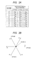
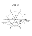
- FIG. 3 shows a transition of the operating state preferentially selected in the model predict ion control.
- a differential vector between the instructed current vector Idqr and the predicted current vector Idqe is defined as a vector Edq indicating a current error.
- the determining unit 34 of the control device 20 selects the voltage vector V 3 from the effective voltage vectors V 3 and V 4 which form smaller angles with the average voltage vector Va (i.e., angles between the vector Va and the vectors V 3 and V 4 are smaller than angles between the vector Va and the other effective voltage vectors V 1 , V 2 , V 5 and V 6 ). That is, the direction of the vector Va is placed between directions of the vectors V 3 and V 4 .
- the inverter IV is set in the operating state corresponding to the selected voltage vector V 3 in the next control period.
- the determining unit 34 selects the other voltage vector V 4 forming a smaller angle with the vector Va.
- the inverter IV changes the operating state corresponding to the vector V 3 to the operating state corresponding to the voltage vector V 4 .
- the determining unit 34 selects one zero voltage vector V 7 .
- the inverter IV changes the operating state corresponding to the vector V 4 to the operating state corresponding to the voltage vector V 7 .
- the control device 20 can lengthen the period of the operating state corresponding to the zero voltage vector. Accordingly, the number of average changing times of the switching states in the inverter IV can be reduced.
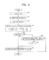
- FIG. 4 is a flow chart showing the processing in the model prediction control according to this embodiment. This processing is performed by the control device 20 every control period Tc, and each control period Tc is started at a renewing (or setting) timing.
- the inverter IV is set in an operating state corresponding to a voltage vector V(n) at the renewing timing of the present control period Tc(n), and this voltage vector V(n) is finally determined in the control device 20 in the preceding control period Tc(n ⁇ 1) earlier than the present control period Tc(n) by one control period.
- the predicting unit 33 provisionally sets a voltage vector V(n), indicating the present operating state actually set in the inverter IV in the present control period Tc(n), as a voltage vector V(n+1).
- the inverter IV is planned to be set in an operating state corresponding to the voltage vector V(n+1) at the renewing timing of the next control period Tc(n+1).
- the first predicting block 33 b of the predicting unit 33 predicts a current vector Idqe(n+2) flowing through the generator 10 in the control period Tc(n+2), on the assumption that the inverter IV is set in the operating state corresponding to the voltage vector V(n+1) at the renewing timing of the next control period Tc(n+1).
- the control period Tc(n+2) is later than the next control period Tc(n+1) by the time length of one control period.
- a second predicting block 33 c predicts a current vector Idqe(n+1) flowing through the generator 10 in the control period Tc(n+1).
- the predicting block 33 b performs the prediction by using the current vector Idqe(n+1).
- This predicting process will be described in detail with reference to FIG. 5 .
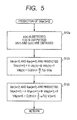
- FIG. 5 is a flow chart showing the processing for predicting the current vector Idqe(n+2) performed in the predicting unit 33 according to this embodiment.
- a rotational angle ⁇ (n) expressed by electrical angle is detected, the voltage vector V(n) determined in the preceding control period Tc(n ⁇ 1) is outputted to the control section 26 to set the inverter IV in the operating state corresponding to the voltage vector V(n) at the renewing timing of the present control period Tc(n), and the current Idq(n) (Id(n), Iq(n)) selected in the selecting block 33 a is obtained.
- phase currents Iu, Iv and Iw are detected by the sensor 16 at the renewing timing of the present control period Tc(n).
- the current (Ide(n), Iqe(n)) is used as an initial value, and a voltage vector defined on the dq rotational coordinate system is used.
- the voltage vector Vdq(n) defined on the dq rotational coordinate system is obtained by performing the dq conversion for the voltage vector V(n) defined on the fixed coordinate system by using the value ⁇ (n)+ ⁇ Tc/2.
- the dq conversion differs from the calculation based on the forward difference method, the dq conversion is performed to suppress the discrete error caused by the forward difference method.
- the predicted current Idqe(n+1) of the next current period Tc(n+1) calculated at step S 12 b is used as an initial value, and a voltage vector Vdq(n+1) defined on the dq rotational coordinate system is used.
- This voltage vector Vdq(n+1) is obtained by performing the dq conversion for the voltage vector V(n+1) defined on the fixed coordinate system by using the value ⁇ (n)+3 ⁇ Tc/2.
- Vda R ⁇ Idr ⁇ Lq ⁇ Iqr (E1)
- Vqa ⁇ Ld ⁇ Idr+R ⁇ Iqr+ ⁇ (E2)
- the determining unit 34 judges whether or not the current error
- i.e., the norm of the current error vector Edq
- the determining unit 34 judges whether or not the plus or minus sign of the difference
- the determining unit 34 judges whether or not the present voltage vector V(n) already set at this time coincides with one of two effective voltage vectors which form smaller angles with the average voltage vector Va than angles between the vector Va and the other effective voltage vectors (second condition).
- the voltage vector V(n) coincides with one of the two voltage vectors
- the logical multiply of the first condition and the second condition is true (YES at step S 20 ).
- the determining unit 34 sets a state transition allowing flag Fa at “1”, and the procedure proceeds to step S 22 .
- the processing shown in FIG. 4 is ended in this control period Tc.
- step S 22 although the voltage vector V(n+1) corresponding to the next operating state planned to be set in the inverter IV at the renewing timing of the next control period Tc(n+1) has been set at step S 10 shown in FIG. 4 , the determining unit 34 performs the processing for examining whether or not the voltage vector V(n+1) should be replaced with another voltage vector.
- the determining unit 34 determines to replace the voltage vector V(n+1) with a specific voltage vector Vs
- the determining unit 34 finally determines to set the inverter IV in an operating state corresponding to the specific voltage vector Vs. This processing will be described in detail with reference to FIG. 6 . Then, the processing shown in FIG. 4 is finished in this control period Tc.
- the determining unit 34 selects the voltage vector V(n+1) coinciding with the voltage vector V(n), and the inverter IV is set in the operating state corresponding to this voltage vector V(n+1) in the next control period Tc(n+1).
- the determining unit 34 performs the processing for examining whether or not the voltage vector V(n+1) should be replaced with another voltage vector.
- the determining unit 34 performs the processing for examining whether or not the voltage vector V(n+1) should be replaced with another voltage vector.
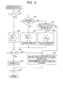
- FIG. 6 is a flow chart showing the processing for examining the replacement of the voltage vector V(n+1) in the determining unit 34 according to this embodiment.
- the determining unit 34 judges whether or not the allowing flag Fa is set at “1”.
- the flag F is set at “1” (YES at step S 30 )
- the determining unit 34 detects that the voltage vector V(n+1) coinciding with the voltage vector V(n) is one of two voltage vectors V(n) forming smaller angles with the average voltage vector Va.
- the determining unit 34 selects a voltage vector, which differs from the present voltage vector V(n) forming a smaller angle with the average voltage vector Va and forms a smaller angle with the average voltage vector Va, as an examining voltage vector Ve. That is, the vectors V(n) and Ve form smaller angles with the vector Va. Then, the determining unit 34 gives priority to an examining operating state corresponding to the examining voltage vector Ve. The determining unit 34 sets this examining operating state having the priority as an object of the examination. In this examination, it is determined whether or not the voltage vector V (n+1) supposedly set at step S 10 shown in FIG. 4 should be replaced with the examining voltage vector Ve.
- the number of phases, of which the switching states are changed to set the inverter IV in the examining operating state is only one.
- step S 34 the determining unit 34 judges whether or not the present voltage vector V(n) is one effective voltage vector. This process is performed to preferentially select one operating state corresponding to a specific effective voltage vector as an object of the examination when the current error is placed at the point P 1 shown in FIG. 3 .
- the control device 20 selects an examining voltage vector Ve which is one of effective voltage vectors forming smaller angles with the average voltage vector Va and indicates an examining operating state changed from the present operating state corresponding to the present voltage vector V(n) by a low switching state changing operation of the inverter IV.
- the number of phases, of which the switching states are changed to set the inverter IV in the examining operating state is one or less.
- the determining unit 34 gives priority to the examining operating state to set the examining operating state as an object of the examination.
- effective voltage vectors V 3 and V 4 form smaller angles with the average voltage vector Va, and the present voltage vector V(n) is a zero voltage vector V 0 .
- the number of phases, of which the switching states are changed to set the inverter IV in the operating state corresponding to the voltage vector V 3 is one (see FIG. 2A )
- the number of phases, of which the switching states are changed to set the inverter IV in the operating state corresponding to the voltage vector V 4 is two (see FIG. 2A ). Therefore, the operating state corresponding to the voltage vector V 3 is set as an object of the examination.
- the determining unit 34 judges whether or not one effective voltage vector Vj forming the angle of A (A ⁇ 20 degrees) with the average voltage vector Va exists in the voltage vectors V 1 to V 6 (first judgment), and it is judged whether or not the voltage vector V(n ⁇ 1) set in the inverter IV just before being changed to the present voltage vector V(n) is one effective voltage vector (second judgment).
- the second judgment is performed to preferentially select one zero voltage vector when the current error is placed at the point P 3 shown in FIG. 3 .
- the determining unit 34 gives priority to an examining operating state corresponding to an examining zero voltage vector Ve on condition that the number of phases, of which the switching states are changed in a change of the present voltage vector V(n) to the examining zero voltage vector, is one or less. Then, the determining unit 34 sets the examining operating state as an object of the examination. For example, when the present voltage vector V(n) is the voltage vector V 4 , the examining operating state corresponding to the examining zero voltage vector V 7 is set as an object of the examination. When the present voltage vector V(n) is the voltage vector V 3 , the examining operating state corresponding to the examining zero voltage vector V 0 is set as an object of the examination.
- the determining unit 34 selects the examining voltage vector Ve, corresponding to the examining operating state set as an object of the examination, as a specific voltage vector Vs of the next control period Tc(n+1). That is, the voltage vector V(n+1) set at step S 10 is replaced with the specific voltage vector Vs selected at step S 46 . Then, the procedure proceeds to step S 48 .
- step S 44 all particular voltage vectors satisfying a first condition are selected from the voltage vectors V 0 to V 7 .
- the first condition in the selection of each particular voltage vector is that the number of phases, of which the switching states are changed in a change of the voltage vector V(n) to the particular voltage vector, is one or less.
- one of the particular voltage vectors satisfying a second condition is selected as a specific voltage vector Vs.
- the second condition is that the estimation based on the estimating function J for the selected particular voltage vector indicates the highest level among levels in the estimation for the particular voltage vectors.
- step S 48 the allowing flag Fa is initialized to “0” so as not to allow the state transfer, and the processing shown in FIG. 6 is ended.
- the voltage vector V(n) is one of two voltage vectors forming smaller angles with the average voltage vector Va while the current error
- one voltage vector coinciding with the other voltage vector forming a smaller angle with the average voltage vector Va is selected as a specific voltage vector Vs on condition that the current error
- one effective voltage vector coinciding with one of two voltage vectors forming smaller angles with the average voltage vector Va is selected as a specific voltage vector Vs on condition that the number of phases, of which the switching states are changed, is one or less while the current error
- particular voltage vectors are selected on condition that the number of phases, of which the switching states are changed in the change to each particular voltage vector, is one or les, and one of the particular voltage vectors is selected as a specific voltage vector Vs on condition that the estimation based on the estimating function J for the selected operating state is the highest level.
- the inverter IV is set in the operating state corresponding to the specific voltage vector Vs in the next control period Tc(n+1) under control of the control unit 26 .
- the phase of the actual current is delayed. Therefore, the speed of response in the model prediction control is lowered, so that the controllability of the control device 20 in the model prediction control is also lowered.
- the alternating current Idqe(n) (Ide(n), Iqe(n)) already predicted in the preceding control period Tc(n ⁇ 1) at step S 12 b shown in FIG.
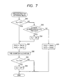
- FIG. 7 is a flow chart showing the processing for obtaining a current Idq(n) from the selecting block 33 a to be used as an initial value for the prediction of a current Idqe(n+1). This processing is performed every control period Tc, and the inverter IV has been actually set in the operating state corresponding to the voltage vector V(n) in this control period Tc(n).
- step S 50 it is judged whether or not a current detection prohibiting flag Fp is set in an on state.
- this prohibiting flag Fp has been set in the on state, it is prohibited to use the actual current Idq(n) as an initial value for the prediction of the current Idqe(n+1).
- step S 52 it is judged whether or not at least one switching state has been changed because of the setting of the operating state corresponding to the voltage vector V(n) in the inverter IV in this control period Tc(n).
- the predicted current Idqe(n+1) is used to determine a voltage vector V(n+1). Then, the processing shown in FIG. 7 is ended. Therefore, the current value detected by the sensor 16 is used for the process at step S 12 a shown in FIG. 5 .
- step S 54 the prohibiting flag Fp is changed to the on state.
- step S 56 the procedure proceeds to step S 58 .
- step S 60 the operation of a time counter is started to measure an elapsed time started at the start of the time counter.
- This process is performed to detect a timing at which the prohibition on the use of the actual current Idqa(n) as an initial value for the prediction of the current Idqe(n+1) is withdrawn.
- a predetermined period of time equal to the threshold value Tth is elapsed after a change in at least one switching state, the influence of ringing caused in the phase currents Iu, Iv and Iw by the change of the switching state can be sufficiently reduced.
- the threshold value Tth be set as shorter as possible on condition that it is assumed that the influence of ringing is sufficiently reduced after the elapsed time equal to the threshold value Tth.
- the threshold value Tth is set to be longer than one control period Tc.
- step S 64 the prohibiting flag Fp is changed to an off state, and the processing shown in FIG. 7 is ended.
- the processing shown in FIG. 7 is ended.
- FIG. 8 is a time chart exemplarily showing the relation between a response time of current and a prohibiting period Tth. As shown in FIG.
- each phase current is rapidly changed, and then being slowly changed while approaching a response time of current.
- the influence of a model error is increased after the change in the switching state.
- the use of the predicted current Idqe(n) as an initial value for the prediction of the current Idqe(n+1) is useful when the influence of the model error is negligible.
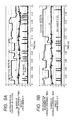
- FIG. 9A is a time chart showing a transition of the voltage vector with a change of the phase current Iu and an SW change flag according to a comparative prior art
- FIG. 9B is a time chart showing a transition of the voltage vector with a change of the phase current Iu and an SW change flag according to this embodiment.
- the SW change flag indicates a change in at least one switching state. Because the voltage vector and the SW change flag are indicated by signals outputted from a dedicated circuit, these are fluctuated. However, this fluctuation has no meaning, but the voltage vector changed in a step shape indicates a change of the voltage vector.
- the number of average changing times of switching state is 46700 per second according to the comparative prior art.
- the number of average changing times of switching state is reduced to 36893 per second according to this embodiment. That is, the number of average changing times is reduced by 20% as compared with that in the comparative prior art. Therefore, this reduction indicates that the switching operation of the switching elements inappropriately per formed due to the influence of ringing is suppressed.
- the number of average changing times of switching state in the triangular wave comparison PWM control is 60000 per second.
- the predicting unit 33 sets phase currents Iu, Iv and Iw, actually detected from the generator 10 , as an initial value to predict the current Idqe(n+2) on the basis of the initial value as an input parameter in the operating state determination of the determining unit 34 , and predicts the current Idqe(n+2) as the input parameter in the predetermined period of time Tth, starting at a time when one operating state set in the electric power inverter circuit is changed to another one, by using the current Idqe(n+1), which has been predicted based on the phase currents Iu, Iv and Iw detected before the change of the operating state set in the inverter IV, as the initial value in place of a value of the controlled variable or the physical quantity detected in the predetermined period of time.
- the current Idqe(n+2) predicted in the predicting unit 33 during the predetermined period of time Tth is set as another initial value which is used to predict another current Idqe(n+3) in a next control period Tc(n+1) during the predetermined period of time Tth as a next input parameter in the operating state determination of the determining unit 34 . Therefore, the predicted current Idqe(n+2) can be used as the initial value for the prediction of the current Idqe(n+3).
- the predicting unit 33 has the first predicting block 33 b that predicts the current Idqe(n+2) acting as the input parameter in the operating state determination, and the second predicting block 33 c that predicts the current Idqe(n+1), on condition that the inverter IV is set in the operating state corresponding to the voltage vector V(n), as the initial value used for the prediction of the first predicting block 33 b in the predetermined period of time Tth.
- the prediction of the predicting unit 33 is performed every control period Tc, the determination of the determining unit 34 is performed every control period Tc, the control unit 26 sets the inverter IV in a specific operating state corresponding to a specific voltage vector Vs every control period Tc, the operating state corresponding to the voltage vector V(n+1) is determined by the determining unit 26 by using the current Idqe(n+2) predicted by the first predicting block 33 b while using the current Idqe(n+1) predicted by the second predicting block 33 c as the initial value used for the prediction of the first predicting block 33 b , the inverter IV is set in the operating state corresponding to the voltage vector V(n+1) at a setting timing of the next control period Tc(n+1), and the first predicting block 33 b predicts the current Idqe(n+2) which is intended to be set in the generator 10 at a time elapsed from the setting timing of the next control period Tc(n+1) by one control period.
- the inverter IV is set in the operating state corresponding to the voltage vector V(n) determined by the determining unit 26 at a setting timing of the control period Tc(n) preceding the next control period Tc(n), and the second predicting block 33 c predicts the current Idqe(n+1), set in the generator 10 at a time elapsed from the setting timing of the present control period Tc(n) by one control period, on the basis of the second operating state corresponding to the voltage vector V(n) by using the phase currents Iu, Iv and Iw detected at the setting timing of the present control period Tc(n) as an initial value.
- the current Idqe(n) already predicted is used, in place of the phase currents Iu, Iv and Iw detected by the sensor 16 , as an initial value for the prediction of the current Idqe(n+1). Therefore, even when ringing caused by a change in switching state is superimposed onto the phase currents Iu, Iv and Iw, the current Idqe(n+1) of the next control period Tc(n+1) can be predicted in the present control period Tc(n) without being influenced by the ringing. Accordingly, the precision in the prediction of the current Idqe(n+1) can be enhanced, and the controllability of the control device 20 for the switching elements of the inverter IV and the generator 10 in the model prediction control can be heightened.
- the predicted current (Ide(n+1), Iqe(n+1)) of the next current period Tc(n+1) used as an initial value for the prediction of the current (Ide(n+2), Iqe(n+2)) is predicted based on the current (Ide(n), Iqe(n)) already predicted when the influence of ringing exists, and is predicted based on the phase currents Iu, Iv and Iw detected by the sensor 16 when influence of ringing is sufficiently reduced.
- the predicted current (Ide(n+1), Iqe(n+1)) of the next current period Tc(n+1) is used as an initial value for the prediction of the current (Ide(n+2), Iqe(n+2))
- the predicted current (Ide(n+1), Iqe(n+1)) can be an appropriate value as an initial value for the prediction of the current (Ide(n+2), Iqe(n+2)) while avoiding impossible or very difficult conditions.
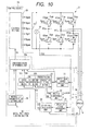
- FIG. 10 is a view showing the structure of a control system having a control device 20 A according to the second embodiment.
- a control system has the battery 12 , the inverter IV, the generator 10 , and a control device 20 A for receiving a target torque Tr, receiving detection values from the sensors 14 and 16 or physical values, and determining an operating state of the inverter IV such that the generator 10 appropriately generates a torque matching with the target torque Tr.
- a torque generated in the generator 10 and a magnetic flux induced in the generator 10 are set as controlled variable.
- An alternating current flowing through the generator 10 to generate and induce the torque and the magnetic flux in the generator 10 is set as a physical quantity.
- the control variable can be determined from the physical quantity.
- the control device 20 A directly controls the current (i.e., the physical value) of the generator 10 to adjust the torque and the magnetic flux at a target torque and an instructed magnetic flux. Therefore, the control device 20 A indirectly controls the torque and the magnetic flux of the generator 10 to adjust the torque and the magnetic flux at a target torque and an instructed magnetic flux.
- the control device 20 A differs from the control device 20 shown in FIG. 1 in that the control device 20 A has a model prediction control section (i.e., a state determining section) 30 A in place of the section 30 shown in FIG. 1 .
- the section 30 A has the predicting unit 33 , a torque and magnetic flux predicting unit 37 , an instructed magnetic flux setting unit 38 and a controlled state determining unit 34 a.
- the predicting unit 33 receives phase currents Iu, Iv and Iw and a rotational angle ⁇ of the generator 10 from the sensors 16 and 14 every control period Tc.
- the control device 20 A can calculate a torque and a magnetic flux of the generator 10 by using the phase currents Iu, Iv and Iw as input parameters.
- the variables ⁇ d, ⁇ q and T are calculated as the predicted magnetic flux components ⁇ de and ⁇ qe and the predicted torque Te.
- the setting unit 38 has a magnetic flux map indicating the relation between a torque and a magnetic flux vector.
- the setting unit 38 receives a target torque Tr and sets an instructed magnetic flux vector ⁇ r( ⁇ dr, ⁇ qr) corresponding to the target torque Tr by referring to the map.
- the vector ⁇ r is set so as to satisfy the requirement of the maximum torque control and the like. In this maximum torque control, the maximum torque is generated in the generator 10 from the minimum current.
- the determining unit 34 a calculates a value of an estimating function J by using the predicted magnetic flux vector ⁇ e, the predicted torque Te, the instructed magnetic flux vector ⁇ r and the target torque Tr each time the producing unit 31 outputs one voltage vector. Then, the unit 34 a determines a specific voltage vector Vs corresponding to the value of the function J, indicating the highest level of estimation, so as to set the inverter IV in a specific operating state corresponding to the specific voltage vector Vs in the next control period.
- the unit 34 a determines the voltage vector Vs corresponding to the minimum value of the function J among the values of the function J calculated by using the respective voltage vectors V 0 to V 7 .
- the weighting factors ⁇ and ⁇ are used to compensate the difference in magnitude between the torque and magnetic flux. For example, assuming that no weighting factor is used for the function J, when the value of the torque is higher than the value of the magnetic flux, the contribution of the error E ⁇ of the magnetic flux to the function J is lowered. In this embodiment, because of the use of the weighting factors ⁇ and ⁇ , the error E ⁇ of the magnetic flux and the error ET of the torque can equally contribute to the function J.
- the predicted torque Te(n+1) and the predicted magnetic flux vector ⁇ e(n+1) used as input parameters of the estimating function J are calculated by using the actual phase currents Iu, Iv and Iw detected by the sensor 16 or the current Idqe(n) already predicted based on the actual phase currents Iu, Iv and Iw. Because the control system has no hardware component for directly detecting a torque and a magnetic flux of the generator 10 , the phase currents Iu, Iv and Iw of the generator, from which a torque and a magnetic flux of the generator 10 can be determined, are detected, and the torque and magnetic flux of the generator 10 are calculated by using the currents Iu, Iv and Iw.
- a current Idqe(n+2) (Ide(n+2), Iqe(n+2)) is predicted on the assumption that the inverter IV is set in an operating state corresponding to the next voltage vector V(n+1) at the renewing timing of the next control period Tc(n+1), and the predicted torque Te and the predicted magnetic flux vector ⁇ e are determined by using the predicted current Idqe(n+2).
- the current Idqe(n+1) of the generator 10 set just after a change in at least one switching state, in place of the actual phase currents Iu, Iv and Iw detected by the sensor 16 just after the change in at least one switching state, the current Idqe(n) already predicted in the second predicting block 33 c at the renewing timing of the preceding control period Tc(n ⁇ 1) by using the actual phase currents Iu, Iv and Iw detected before the change in at least one switching state.
- control device 20 A can control the phase currents Iu, Iv and Iw (i.e., physical values) of the generator 10 by using phase currents Iu, Iv and Iw detected by the sensor 16 , the target torque Tr and the instructed magnetic flux ⁇ r, the control device 20 A can indirectly control the torque and magnetic flux (i.e., controlled variables) of the generator 10 .
- the current Idqe(n) already predicted is used, in place of the phase currents Iu, Iv and Iw detected by the sensor 16 , as an initial value for the prediction of the current Idqe(n+1).
- the control device 20 or 20 A may store the phase currents Iu, Iv and Iw at the past prohibiting time in advance to use the actual current Idqa determined from the stored phase currents Iu, Iv and Iw as an initial value for the prediction of the current Idqe(n+1) when the influence of ringing exists in the phase currents Iu, Iv and Iw in the present control period Tc(n).
- the phase currents Iu, Iv and Iw are detected by the sensor 16 at the change time of each control period.
- the phase currents Iu, Iv and Iw may be detected at any time of each control period.
- the phase currents Iu, Iv and Iw can be detected as an initial value for the prediction of a current when the inverter IV is set in an operation state at the change time of the present control period.
- controlled variables at the change time of a second control period later than the first control period by the time length of one control period are predicted.
- controlled variables at any time between the first and second control periods may be predicted.
- the determination of the operating state set in the inverter IV is not limited to the method described in the embodiments. For example, even when the operating state set in the inverter IV is determined based on the predicted value and the instructed value of current denoting controlled variables, the operating state my be determined by comparing values of the estimating function J determined for all voltage vectors V 0 to V 7 produced in the setting unit 31 .
- the input parameter of the estimating function J may be the sum
- the input parameter of the estimating function J is arbitrary on condition that the level of estimation becomes low as the difference between instructed values Idr and Iqr of current (i.e., controlled variables) and predicted values Ide and Iqe of current (i.e., controlled variables) becomes large.
- predicted values of current (i.e., controlled variables) in a first control period, later than one control period from a second control period, in which an operation state is set in the inverter IV are used as input parameters for the determination of an operating state of the first control period.
- predicted values of current (i.e., controlled variables) in the first control period and control periods following the first control period may be used as input parameters for the determination of an operating state of the first control period when an operation state is set in the inverter IV in the second control period earlier than the first control period by one control period.
- the inverter IV is representatively used as an electric power inverter circuit with a plurality of switching elements which sets a plurality of connecting points, being connected with respective terminals of an electric rotating machine represented by the motor generator 10 , at respective electric potentials different from one another by selecting two switching elements or more from the switching elements and changing the state of each selected switching element to another one and adjusts controlled variables of the generator 10 represented by the phase currents flowing through the generator 10 .
- the electric power inverter circuit in the present invention is not limited to the inverter IV.
- Any device with a plurality of switching elements can be selected as an electric power inverter circuit on condition that the device sets three connecting points or more, being connected with respective terminals of an electric rotating machine, at respective electric potentials different from one another by changing the state of each selected switching element to another one.
- Japanese Patent First Publication No. 2006-174697 discloses an electric power inverter circuit which applies three electric potentials or more different from one another to respective terminals of an electric rotating machine.
- a torque and a magnetic flux of the generator 10 or phase currents of the generator 10 are set as controlled variables which are used to determine the operating state of the inverter IV by using an instructed value and predicted values.
- a torque or only a magnetic flux of the generator 10 may be set as a controlled variable, or both a torque and a current of the generator 10 may be set as controlled variables.
- a control device may control the inverter IV and the generator 10 by using a detected value of a sensor which detects information about the operation of the generator 10 other than a current of the generator 10 .
- the torque of the generator 10 is finally controlled to the target torque Tr regardless of whether the torque of the machine is predicted, the torque is adopted as the ultimate controlled variable of the electric rotating machine.
- a rotational speed or the like of the generator 10 may be adopted as the ultimate controlled variable.
- the interior permanent magnet synchronous motor is used in the embodiments.
- any synchronous motor such as a surface magnet synchronous motor or a field winding synchronous motor may be used as the electric rotating machine.
- any induction electric rotating machine such as an induction motor or the like may be used.
- the present invention is not limited to a secondary battery.
- a fuel cell may be used.
- the high-voltage battery 12 is adopted as the direct current source.
- output terminals of a converter boosting the output voltage of the battery 12 may be adopted.
Landscapes
- Engineering & Computer Science (AREA)
- Power Engineering (AREA)
- Control Of Ac Motors In General (AREA)
Abstract
Description
Vd=(R+pLd)Id−ω·Lq·Iq (c1)
Vq=ω·Ld·Id+(R+pLq)Iq+ω·φ (c2)
pID=−(R/Ld)Id+ω(Lq/Ld)Iq+Vd/Ld (c3)
pIq=−ω(Ld/Lq)Id−(R/Lq)Iq+Vq/Lq−ω·φ/Lq (c4)
The combination of the equations (c3) and (c4) is expressed as follows:
Vda=R·Idr−ω·Lq·Iqr (E1)
Vqa=ω·Ld·Idr+R·Iqr+ω·φ (E2)
φd=Ld·Id+φ (c5)
φq=Lq·Iq (c6)
T=P(φd·Iq−φq·Id) (c7)
where the parameter P denotes the number of pole pairs. In this prediction, by replacing variables Id and Iq with the predicted currents Ide and Iqe, the variables φd, φq and T are calculated as the predicted magnetic flux components φde and φqe and the predicted torque Te.
Claims (7)
Applications Claiming Priority (2)
| Application Number | Priority Date | Filing Date | Title |
|---|---|---|---|
| JP2010210481A JP5177195B2 (en) | 2010-09-21 | 2010-09-21 | Rotating machine control device |
| JP2010-210481 | 2010-09-21 |
Publications (2)
| Publication Number | Publication Date |
|---|---|
| US20120068641A1 US20120068641A1 (en) | 2012-03-22 |
| US8441220B2 true US8441220B2 (en) | 2013-05-14 |
Family
ID=45817148
Family Applications (1)
| Application Number | Title | Priority Date | Filing Date |
|---|---|---|---|
| US13/238,309 Expired - Fee Related US8441220B2 (en) | 2010-09-21 | 2011-09-21 | Control device for electric rotating machine |
Country Status (2)
| Country | Link |
|---|---|
| US (1) | US8441220B2 (en) |
| JP (1) | JP5177195B2 (en) |
Cited By (9)
| Publication number | Priority date | Publication date | Assignee | Title |
|---|---|---|---|---|
| US9214862B2 (en) | 2014-04-17 | 2015-12-15 | Philips International, B.V. | Systems and methods for valley switching in a switching power converter |
| US9253833B2 (en) | 2013-05-17 | 2016-02-02 | Cirrus Logic, Inc. | Single pin control of bipolar junction transistor (BJT)-based power stage |
| US9496855B2 (en) | 2013-07-29 | 2016-11-15 | Cirrus Logic, Inc. | Two terminal drive of bipolar junction transistor (BJT) of a light emitting diode (LED)-based bulb |
| US9504106B2 (en) | 2013-07-29 | 2016-11-22 | Cirrus Logic, Inc. | Compensating for a reverse recovery time period of a bipolar junction transistor (BJT) in switch-mode operation of a light-emitting diode (LED)-based bulb |
| US9504118B2 (en) | 2015-02-17 | 2016-11-22 | Cirrus Logic, Inc. | Resistance measurement of a resistor in a bipolar junction transistor (BJT)-based power stage |
| US9603206B2 (en) | 2015-02-27 | 2017-03-21 | Cirrus Logic, Inc. | Detection and control mechanism for tail current in a bipolar junction transistor (BJT)-based power stage |
| US9609701B2 (en) | 2015-02-27 | 2017-03-28 | Cirrus Logic, Inc. | Switch-mode drive sensing of reverse recovery in bipolar junction transistor (BJT)-based power converters |
| US9735671B2 (en) | 2013-05-17 | 2017-08-15 | Cirrus Logic, Inc. | Charge pump-based drive circuitry for bipolar junction transistor (BJT)-based power supply |
| WO2022025810A1 (en) | 2020-07-29 | 2022-02-03 | Fingerprint Cards Anacatum Ip Ab | Adaptive readout from a global shutter optical biometric sensor |
Families Citing this family (17)
| Publication number | Priority date | Publication date | Assignee | Title |
|---|---|---|---|---|
| JP5880967B2 (en) * | 2012-09-28 | 2016-03-09 | 株式会社デンソー | AC motor control device |
| EP2733842B1 (en) * | 2012-11-15 | 2018-07-04 | ABB Schweiz AG | Controlling an electrical converter |
| JP5812021B2 (en) * | 2013-02-08 | 2015-11-11 | 株式会社デンソー | AC motor control device |
| US9702763B2 (en) | 2013-06-17 | 2017-07-11 | Taiwan Semiconductor Manufacturing Company, Ltd. | Thermal sensor |
| US9354124B2 (en) * | 2013-06-17 | 2016-05-31 | Taiwan Semiconductor Manufacturing Company, Ltd. | Temperature/voltage detection circuit |
| US9444384B2 (en) | 2014-07-16 | 2016-09-13 | Atieva, Inc. | Direct torque control motor controller with transient current limiter |
| US9431951B2 (en) | 2014-07-16 | 2016-08-30 | Atieva, Inc. | Direct torque control motor controller with transient current limiter |
| US9407189B2 (en) * | 2014-07-16 | 2016-08-02 | Atieva, Inc. | Direct torque control motor controller with torque ripple reduction |
| DE102014213985B4 (en) * | 2014-07-17 | 2024-03-28 | Magna powertrain gmbh & co kg | Method for controlling a field-exciting current |
| CN105490605A (en) * | 2015-12-16 | 2016-04-13 | 上海新时达电气股份有限公司 | Online adjustment method for prediction control model parameters of induction motor |
| DE102016000743A1 (en) * | 2016-01-26 | 2017-07-27 | András Lelkes | Method for controlling an electrically excited motor and converter |
| US10840841B2 (en) * | 2018-09-27 | 2020-11-17 | Tmeic Corporation | Control device for power conversion device, control method, and motor drive system |
| KR102699008B1 (en) * | 2019-08-30 | 2024-08-26 | 현대자동차주식회사 | System and method for increasing temperature of battery |
| CN111130419A (en) * | 2020-01-03 | 2020-05-08 | 天津大学 | Predictive flux linkage control method for permanent magnet motor based on extended step size and variable action time |
| CN111049458A (en) * | 2020-01-05 | 2020-04-21 | 天津大学 | Permanent magnet synchronous motor current control method based on variable vector action duration |
| JP6885489B1 (en) * | 2020-04-16 | 2021-06-16 | 株式会社明電舎 | Power conversion system and control method of power conversion system |
| CN112016197B (en) * | 2020-08-18 | 2021-04-13 | 浙江大学 | Prediction method for harmonic current of permanent magnet motor |
Citations (10)
| Publication number | Priority date | Publication date | Assignee | Title |
|---|---|---|---|---|
| JP3221686B2 (en) | 1991-02-28 | 2001-10-22 | 松下電器産業株式会社 | Signal generator for motor speed control |
| US20030030404A1 (en) | 2001-06-06 | 2003-02-13 | Hitachi, Ltd. | Sensorless control system for synchronous motor |
| JP2003219678A (en) | 2002-01-17 | 2003-07-31 | Hitachi Ltd | Synchronous motor drive |
| JP2004048868A (en) | 2002-07-10 | 2004-02-12 | Hitachi Ltd | Speed controller for synchronous motor |
| US6756760B2 (en) * | 2000-03-03 | 2004-06-29 | Seiko Epson Corporation | Motor control device and motor control method |
| JP2008228419A (en) | 2007-03-12 | 2008-09-25 | Mie Univ | Motor torque control method based on model predictive control |
| US20090160376A1 (en) * | 2007-12-19 | 2009-06-25 | Denso Corporation | Control system for multiphase rotary machines |
| US20090160377A1 (en) * | 2007-12-19 | 2009-06-25 | Denso Corporation | Control system for multiphase rotary machines |
| JP4422875B2 (en) | 2000-08-30 | 2010-02-24 | キヤノン株式会社 | Motor drive device |
| JP2010074902A (en) | 2008-09-17 | 2010-04-02 | Ricoh Co Ltd | Control method of motor drive unit |
Family Cites Families (2)
| Publication number | Priority date | Publication date | Assignee | Title |
|---|---|---|---|---|
| JP2008067556A (en) * | 2006-09-11 | 2008-03-21 | Sanyo Electric Co Ltd | Motor controller |
| JP5391698B2 (en) * | 2009-01-16 | 2014-01-15 | 株式会社デンソー | Rotating machine control device and control system |
-
2010
- 2010-09-21 JP JP2010210481A patent/JP5177195B2/en not_active Expired - Fee Related
-
2011
- 2011-09-21 US US13/238,309 patent/US8441220B2/en not_active Expired - Fee Related
Patent Citations (11)
| Publication number | Priority date | Publication date | Assignee | Title |
|---|---|---|---|---|
| JP3221686B2 (en) | 1991-02-28 | 2001-10-22 | 松下電器産業株式会社 | Signal generator for motor speed control |
| US6756760B2 (en) * | 2000-03-03 | 2004-06-29 | Seiko Epson Corporation | Motor control device and motor control method |
| JP4422875B2 (en) | 2000-08-30 | 2010-02-24 | キヤノン株式会社 | Motor drive device |
| US20030030404A1 (en) | 2001-06-06 | 2003-02-13 | Hitachi, Ltd. | Sensorless control system for synchronous motor |
| JP3867518B2 (en) | 2001-06-06 | 2007-01-10 | 株式会社日立製作所 | Sensorless control system for synchronous motor |
| JP2003219678A (en) | 2002-01-17 | 2003-07-31 | Hitachi Ltd | Synchronous motor drive |
| JP2004048868A (en) | 2002-07-10 | 2004-02-12 | Hitachi Ltd | Speed controller for synchronous motor |
| JP2008228419A (en) | 2007-03-12 | 2008-09-25 | Mie Univ | Motor torque control method based on model predictive control |
| US20090160376A1 (en) * | 2007-12-19 | 2009-06-25 | Denso Corporation | Control system for multiphase rotary machines |
| US20090160377A1 (en) * | 2007-12-19 | 2009-06-25 | Denso Corporation | Control system for multiphase rotary machines |
| JP2010074902A (en) | 2008-09-17 | 2010-04-02 | Ricoh Co Ltd | Control method of motor drive unit |
Cited By (9)
| Publication number | Priority date | Publication date | Assignee | Title |
|---|---|---|---|---|
| US9253833B2 (en) | 2013-05-17 | 2016-02-02 | Cirrus Logic, Inc. | Single pin control of bipolar junction transistor (BJT)-based power stage |
| US9735671B2 (en) | 2013-05-17 | 2017-08-15 | Cirrus Logic, Inc. | Charge pump-based drive circuitry for bipolar junction transistor (BJT)-based power supply |
| US9496855B2 (en) | 2013-07-29 | 2016-11-15 | Cirrus Logic, Inc. | Two terminal drive of bipolar junction transistor (BJT) of a light emitting diode (LED)-based bulb |
| US9504106B2 (en) | 2013-07-29 | 2016-11-22 | Cirrus Logic, Inc. | Compensating for a reverse recovery time period of a bipolar junction transistor (BJT) in switch-mode operation of a light-emitting diode (LED)-based bulb |
| US9214862B2 (en) | 2014-04-17 | 2015-12-15 | Philips International, B.V. | Systems and methods for valley switching in a switching power converter |
| US9504118B2 (en) | 2015-02-17 | 2016-11-22 | Cirrus Logic, Inc. | Resistance measurement of a resistor in a bipolar junction transistor (BJT)-based power stage |
| US9603206B2 (en) | 2015-02-27 | 2017-03-21 | Cirrus Logic, Inc. | Detection and control mechanism for tail current in a bipolar junction transistor (BJT)-based power stage |
| US9609701B2 (en) | 2015-02-27 | 2017-03-28 | Cirrus Logic, Inc. | Switch-mode drive sensing of reverse recovery in bipolar junction transistor (BJT)-based power converters |
| WO2022025810A1 (en) | 2020-07-29 | 2022-02-03 | Fingerprint Cards Anacatum Ip Ab | Adaptive readout from a global shutter optical biometric sensor |
Also Published As
| Publication number | Publication date |
|---|---|
| JP5177195B2 (en) | 2013-04-03 |
| JP2012070469A (en) | 2012-04-05 |
| US20120068641A1 (en) | 2012-03-22 |
Similar Documents
| Publication | Publication Date | Title |
|---|---|---|
| US8441220B2 (en) | Control device for electric rotating machine | |
| US8278854B2 (en) | Control device for electric rotating machine | |
| US8310186B2 (en) | Apparatus for carrying out improved control of rotary machine | |
| US8427088B2 (en) | Apparatus for carrying out improved control of rotary machine | |
| US8164311B2 (en) | Control device for electric rotating machine | |
| EP1881596B1 (en) | Motor drive system control device and electric vehicle using the same | |
| US6771039B2 (en) | Motor control apparatus and method | |
| US8497645B2 (en) | Control device for electric motor drive device | |
| CN101540581B (en) | Devices for Improved Control of Rotating Machinery | |
| US7701156B2 (en) | Electric motor drive control system and control method thereof | |
| US20110241583A1 (en) | Control device of motor driving apparatus | |
| US20110241584A1 (en) | Control device of motor driving apparatus | |
| US8063596B2 (en) | Apparatus for carrying out improved control of rotary machine | |
| EP2393200B1 (en) | Controller for ac motor | |
| US8872454B2 (en) | Control unit of rotary device | |
| US6194865B1 (en) | Control method and system for electric rotary machine | |
| US9806653B2 (en) | Control apparatus for motor control system | |
| EP2804311B1 (en) | Inverter control device | |
| EP2804310A1 (en) | Inverter control device | |
| US20120032620A1 (en) | Control device | |
| US8922143B2 (en) | Control system for a rotary machiine | |
| US8816618B2 (en) | Rotary machine control apparatus | |
| JP4452519B2 (en) | DC brushless motor drive control apparatus and method for vehicle propulsion | |
| JP3852289B2 (en) | Motor control device | |
| CN103904982A (en) | Vehicle and control device for vehicle |
Legal Events
| Date | Code | Title | Description |
|---|---|---|---|
| AS | Assignment |
Owner name: DENSO CORPORATION, JAPAN Free format text: ASSIGNMENT OF ASSIGNORS INTEREST;ASSIGNOR:IMURA, AKIHIRO;REEL/FRAME:026941/0106 Effective date: 20110914 |
|
| FEPP | Fee payment procedure |
Free format text: PAYOR NUMBER ASSIGNED (ORIGINAL EVENT CODE: ASPN); ENTITY STATUS OF PATENT OWNER: LARGE ENTITY |
|
| STCF | Information on status: patent grant |
Free format text: PATENTED CASE |
|
| FPAY | Fee payment |
Year of fee payment: 4 |
|
| FEPP | Fee payment procedure |
Free format text: MAINTENANCE FEE REMINDER MAILED (ORIGINAL EVENT CODE: REM.); ENTITY STATUS OF PATENT OWNER: LARGE ENTITY |
|
| LAPS | Lapse for failure to pay maintenance fees |
Free format text: PATENT EXPIRED FOR FAILURE TO PAY MAINTENANCE FEES (ORIGINAL EVENT CODE: EXP.); ENTITY STATUS OF PATENT OWNER: LARGE ENTITY |
|
| STCH | Information on status: patent discontinuation |
Free format text: PATENT EXPIRED DUE TO NONPAYMENT OF MAINTENANCE FEES UNDER 37 CFR 1.362 |
|
| FP | Lapsed due to failure to pay maintenance fee |
Effective date: 20210514 |