US8437867B2 - Implant tool and improved electrode design for minimally invasive procedure - Google Patents
Implant tool and improved electrode design for minimally invasive procedure Download PDFInfo
- Publication number
- US8437867B2 US8437867B2 US13/286,169 US201113286169A US8437867B2 US 8437867 B2 US8437867 B2 US 8437867B2 US 201113286169 A US201113286169 A US 201113286169A US 8437867 B2 US8437867 B2 US 8437867B2
- Authority
- US
- United States
- Prior art keywords
- electrode
- electrode structure
- control system
- interfacing
- baroreflex
- Prior art date
- Legal status (The legal status is an assumption and is not a legal conclusion. Google has not performed a legal analysis and makes no representation as to the accuracy of the status listed.)
- Active
Links
Images


Classifications
-
- A—HUMAN NECESSITIES
- A61—MEDICAL OR VETERINARY SCIENCE; HYGIENE
- A61N—ELECTROTHERAPY; MAGNETOTHERAPY; RADIATION THERAPY; ULTRASOUND THERAPY
- A61N1/00—Electrotherapy; Circuits therefor
- A61N1/02—Details
- A61N1/04—Electrodes
- A61N1/05—Electrodes for implantation or insertion into the body, e.g. heart electrode
- A61N1/0551—Spinal or peripheral nerve electrodes
- A61N1/0558—Anchoring or fixation means therefor
-
- A—HUMAN NECESSITIES
- A61—MEDICAL OR VETERINARY SCIENCE; HYGIENE
- A61N—ELECTROTHERAPY; MAGNETOTHERAPY; RADIATION THERAPY; ULTRASOUND THERAPY
- A61N1/00—Electrotherapy; Circuits therefor
- A61N1/18—Applying electric currents by contact electrodes
- A61N1/32—Applying electric currents by contact electrodes alternating or intermittent currents
- A61N1/36—Applying electric currents by contact electrodes alternating or intermittent currents for stimulation
- A61N1/3605—Implantable neurostimulators for stimulating central or peripheral nerve system
- A61N1/3606—Implantable neurostimulators for stimulating central or peripheral nerve system adapted for a particular treatment
- A61N1/36114—Cardiac control, e.g. by vagal stimulation
- A61N1/36117—Cardiac control, e.g. by vagal stimulation for treating hypertension
-
- A—HUMAN NECESSITIES
- A61—MEDICAL OR VETERINARY SCIENCE; HYGIENE
- A61N—ELECTROTHERAPY; MAGNETOTHERAPY; RADIATION THERAPY; ULTRASOUND THERAPY
- A61N1/00—Electrotherapy; Circuits therefor
- A61N1/18—Applying electric currents by contact electrodes
- A61N1/32—Applying electric currents by contact electrodes alternating or intermittent currents
- A61N1/36—Applying electric currents by contact electrodes alternating or intermittent currents for stimulation
- A61N1/3605—Implantable neurostimulators for stimulating central or peripheral nerve system
- A61N1/36128—Control systems
- A61N1/36135—Control systems using physiological parameters
- A61N1/36139—Control systems using physiological parameters with automatic adjustment
-
- A—HUMAN NECESSITIES
- A61—MEDICAL OR VETERINARY SCIENCE; HYGIENE
- A61N—ELECTROTHERAPY; MAGNETOTHERAPY; RADIATION THERAPY; ULTRASOUND THERAPY
- A61N1/00—Electrotherapy; Circuits therefor
- A61N1/18—Applying electric currents by contact electrodes
- A61N1/32—Applying electric currents by contact electrodes alternating or intermittent currents
- A61N1/36—Applying electric currents by contact electrodes alternating or intermittent currents for stimulation
- A61N1/3605—Implantable neurostimulators for stimulating central or peripheral nerve system
- A61N1/36128—Control systems
- A61N1/36146—Control systems specified by the stimulation parameters
- A61N1/3615—Intensity
- A61N1/3616—Voltage density or current density
-
- A—HUMAN NECESSITIES
- A61—MEDICAL OR VETERINARY SCIENCE; HYGIENE
- A61N—ELECTROTHERAPY; MAGNETOTHERAPY; RADIATION THERAPY; ULTRASOUND THERAPY
- A61N1/00—Electrotherapy; Circuits therefor
- A61N1/18—Applying electric currents by contact electrodes
- A61N1/32—Applying electric currents by contact electrodes alternating or intermittent currents
- A61N1/36—Applying electric currents by contact electrodes alternating or intermittent currents for stimulation
- A61N1/3605—Implantable neurostimulators for stimulating central or peripheral nerve system
- A61N1/36128—Control systems
- A61N1/36146—Control systems specified by the stimulation parameters
- A61N1/36167—Timing, e.g. stimulation onset
- A61N1/36171—Frequency
-
- A—HUMAN NECESSITIES
- A61—MEDICAL OR VETERINARY SCIENCE; HYGIENE
- A61N—ELECTROTHERAPY; MAGNETOTHERAPY; RADIATION THERAPY; ULTRASOUND THERAPY
- A61N1/00—Electrotherapy; Circuits therefor
- A61N1/18—Applying electric currents by contact electrodes
- A61N1/32—Applying electric currents by contact electrodes alternating or intermittent currents
- A61N1/36—Applying electric currents by contact electrodes alternating or intermittent currents for stimulation
- A61N1/3605—Implantable neurostimulators for stimulating central or peripheral nerve system
- A61N1/36128—Control systems
- A61N1/36146—Control systems specified by the stimulation parameters
- A61N1/36167—Timing, e.g. stimulation onset
- A61N1/36175—Pulse width or duty cycle
-
- A—HUMAN NECESSITIES
- A61—MEDICAL OR VETERINARY SCIENCE; HYGIENE
- A61N—ELECTROTHERAPY; MAGNETOTHERAPY; RADIATION THERAPY; ULTRASOUND THERAPY
- A61N1/00—Electrotherapy; Circuits therefor
- A61N1/18—Applying electric currents by contact electrodes
- A61N1/32—Applying electric currents by contact electrodes alternating or intermittent currents
- A61N1/36—Applying electric currents by contact electrodes alternating or intermittent currents for stimulation
- A61N1/3605—Implantable neurostimulators for stimulating central or peripheral nerve system
- A61N1/36128—Control systems
- A61N1/36146—Control systems specified by the stimulation parameters
- A61N1/36182—Direction of the electrical field, e.g. with sleeve around stimulating electrode
Definitions
- the present invention relates generally to baroreflex activation therapy devices and methods, and more particularly to an improved electrode design for use with an implant tool and procedure, as part of a baroreflex activation therapy system.
- Cardiovascular disease is a major contributor to patient illness and mortality. It also is a primary driver of health care expenditure, costing billions of dollars each year in the United States.
- Heart failure is the final common expression of a variety of cardiovascular disorders, including ischemic heart disease. It is characterized by an inability of the heart to pump enough blood to meet the body's needs and results in fatigue, reduced exercise capacity and poor survival. Heart failure results in the activation of a number of body systems to compensate for the heart's inability to pump sufficient blood. Many of these responses are mediated by an increase in the level of activation of the sympathetic nervous system, as well as by activation of multiple other neurohormonal responses.
- this sympathetic nervous system activation signals the heart to increase heart rate and force of contraction to increase the cardiac output; it signals the kidneys to expand the blood volume by retaining sodium and water; and it signals the arterioles to constrict to elevate the blood pressure.
- the cardiac, renal and vascular responses increase the workload of the heart, further accelerating myocardial damage and exacerbating the heart failure state. Accordingly, it is desirable to reduce the level of sympathetic nervous system activation in order to stop or at least minimize this vicious cycle and thereby treat or manage the heart failure.
- Hypertension or high blood pressure
- hypertension is a major cardiovascular disorder that is estimated to affect 65 million people in the United Sates alone. Hypertension occurs when the body's smaller blood vessels (arterioles) constrict, causing an increase in blood pressure. Because the blood vessels constrict, the heart must work harder to maintain blood flow at the higher pressures. Although the body may tolerate short periods of increased blood pressure, sustained hypertension may eventually result in damage to multiple body organs, including the kidneys, brain, eyes and other tissues, causing a variety of maladies associated therewith. The elevated blood pressure may also damage the lining of the blood vessels, accelerating the process of atherosclerosis and increasing the likelihood that a blood clot may develop. This could lead to a heart attack and/or stroke. Sustained high blood pressure may eventually result in an enlarged and damaged heart (hypertrophy), which may lead to heart failure.
- Hypertension is a leading cause of heart failure and stroke, is the primary cause of death for tens of thousands of patients per year, and is listed as a primary or contributing cause of death for hundreds of thousands of patients per year in the U.S. Accordingly, hypertension is a serious health problem demanding significant research and development for the treatment thereof. Hypertension remains a significant risk for patients and challenge for health care providers around the world despite improvements in awareness, prevention, treatment and control over the last 30 years. Patients with hypertension are encouraged to implement lifestyle modifications including weight reduction, adopting the DASH eating plan, reducing dietary sodium, increasing physical activity, and limiting alcohol consumption and smoking A large number of pharmacologic treatments are also currently available to treat hypertension.
- carotid sinus nerve stimulation can negatively affect the patient's breathing patterns as well as blood circulation.
- the paucity of literature on carotid sinus nerve stimulation during time is reflective of this and the lack of any similar or alternate stimulation systems for the treatment of drug resistant hypertension.
- Baroreflex Activation Therapy utilizes electrical, mechanical, chemical, and/or other means of stimulation to activate one or more components of a patient's baroreflex system, such as baroreceptors.
- Baroreceptors are sensory nerve ends that are profusely distributed within the arterial walls of the major arteries, as well in the heart, aortic arch, carotid sinus or arteries, and in the low-pressure side of the vasculature such as the pulmonary artery and vena cava. Baroreceptor signals are used to activate a number of body systems which collectively may be referred to as the baroreflex system. Baroreceptors are connected to the brain via the nervous system, allowing the brain to detect changes in blood pressure, which is indicative of cardiac output.
- the baroreflex system activates a number of body systems, including the heart, kidneys, vessels, and other organs/tissues.
- Such natural activation of the baroreflex system generally corresponds to an increase in neurohormonal activity.
- the baroreflex system initiates a neurohormonal sequence that signals the heart to increase heart rate and increase contraction force in order to increase cardiac output, signals the kidneys to increase blood volume by retaining sodium and water, and signals the vessels to constrict to elevate blood pressure.
- the cardiac, renal and vascular responses increase blood pressure and cardiac output, and thus increase the workload of the heart. In a patient suffering from heart failure, this further accelerates myocardial damage and exacerbates the heart failure state.
- a baroreceptor activation device may be activated, deactivated or otherwise modulated to activate one or more baroreceptors and induce a baroreceptor signal or a change in the baroreceptor signal to thereby affect a change in the baroreflex system.
- the baroreceptor activation device may be activated, deactivated, or otherwise modulated continuously, periodically, or episodically.
- the baroreceptor activation device may utilize electrical as well as mechanical, thermal, chemical, biological, or a combination thereof to activate the baroreceptor.
- the baroreceptor may be activated directly, or activated indirectly via the adjacent vascular tissue. Activation of this reflex increases afferent electrical signals through the carotid sinus nerve (Hering's nerve, a branch of the glossopharyngeal nerve, cranial nerve IX) to the medullary brain centers that regulate autonomic tone. Increased afferent signals to these medullary centers cause a reduction in sympathetic tone and an increase in parasympathetic tone.
- peripheral activation of the baroreflex results in a physiologic response whereby blood pressure is controlled by mechanisms determined by the integrative action of the central nervous system action on all peripheral organs and blood vessels.
- the process of implanting a baroreflex activation device for delivering baroreflex therapy involves positioning the assembly such that the electrodes are properly situated against the arterial wall of the carotid sinus, and securing the electrode assembly to the artery so that the positioning is maintained.
- the process of adjusting and re-adjusting the position of the electrode assembly during implantation adds to the overall procedure time.
- Present-day procedures involve positioning and holding the electrode assembly in place with forceps, hemostat or similar tool while applying the stimulus and observing the response in the patient. Movement by as little as 1 mm can make a medically relevant difference in the effectiveness of the baroreceptor activation.
- mapping methods and techniques for implanting electrodes is disclosed in U.S. Pat. No. 6,850,801 to Kieval et al.
- the positioning is a critical step, as the electrodes must direct as much energy as possible toward the baroreceptors for maximum effectiveness and efficiency.
- the energy source for the implanted baroreflex stimulation device is typically an on-board battery with finite capacity, and it is desirable to provide a lower energy source to ensure patient safety.
- a high-efficiency implantation will provide a longer battery life and correspondingly longer effective service life between surgeries because less energy will be required to achieve the needed degree of therapy.
- the position of the assembly is typically adjusted several times during the implantation procedure in order to optimize the baroreflex response.
- Another challenge related to the positioning process is the task of keeping track of previous desirable positions. Because positioning the electrode assembly is an optimization procedure, surgeons will tend to search for better positions until they have exhausted all reasonable alternative positions. Returning the electrode assembly to a previously-observed optimal position can be quite difficult and frustrating, especially under surgical conditions. Additionally, previous mapping approaches required large incisions to provide clearance for positioning and re-positioning of the electrode assembly.
- An implantable baroreflex activation system includes a control system having an implantable housing, an electrical lead, attachable to the control system, and an electrode structure.
- the electrode structure is near one end of the electrical lead, and includes a monopolar electrode, a backing material having an effective surface area larger than the electrode, and a releasable pivotable interface to mate with an implant tool.
- the electrode is configured for implantation on an outer surface of a blood vessel and the control system is programmed to deliver a baroreflex therapy via the monopolar electrode to a baroreceptor within a wall of the blood vessel.
- a method of implanting a baroreflex activation system includes creating an incision in a patient and releasably coupling an electrode structure to an implant tool, the electrode structure including a monopolar electrode, a backing material having an effective surface area larger than the monopolar electrode, and a means for releasably and pivotably interfacing with the implant tool.
- the method further includes determining a suitable implant location for the electrode structure on a blood vessel by manipulating the implant tool within the incision, securing the electrode structure at the implant location such that the monopolar electrode is in contact with an outer surface of the blood vessel, implanting the housing, and connecting the electrode structure to the control system with the electrical lead.
- FIG. 1 is a cross-sectional schematic illustration of baroreceptors within the vascular wall and the baroreflex system.
- FIG. 2 is a schematic illustration of a baroreceptor activation system in accordance with the present invention.
- FIG. 3A is a plan view of an electrode coupled with a lead according to an embodiment of the present invention.
- FIG. 3B is a close-up inverted view of a portion of FIG. 3A .
- FIG. 4A is an isometric view of an implant tool according to an embodiment of the present invention.
- FIG. 4B is a close-up plan view of the interface tip of the implant tool of FIG. 4A .
- FIG. 4C is a close-up plan view of the implant tool to FIG. 4A coupled with an electrode.
- FIG. 5A is an elevation view of an implant tool according to another embodiment of the present invention.
- FIG. 5B is a close-up elevation view of a portion of FIG. 5A .
- FIG. 6A is an isometric view of the implant tool of FIG. 5A positioned proximate an electrode structure according to an embodiment of the present invention.
- FIG. 6B is an isometric view of the implant tool of FIG. 6A engaged with the electrode structure.
- FIG. 7A is a schematic representation of an electrode structure being implanted on a blood vessel with the use of an implant tool, according to an embodiment of the present invention.
- FIG. 7B is a schematic representation of the electrode structure of FIG. 7A fixed in place on the blood vessel.
- FIGS. 8A and 8B are a schematic representations of a baroreflex activation system according to an embodiment of the present invention implanted on a carotid sinus within a patient.
- FIG. 9A is a plan view of the tissue contact side of an electrode structure according to an embodiment of the present invention.
- FIG. 9B is a perspective view of a fixation member according to an embodiment of the present invention.
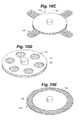
- FIGS. 10A-10E are perspective views of related electrode structure configurations according to embodiments of the present invention.
- FIG. 11A is an isometric view of an electrode structure and fixation mechanism according to an embodiment of the present invention.
- FIG. 11B is an elevation view of an implant tool according to another embodiment of the present invention for use with the electrode arrangement of FIG. 11A .
- FIG. 11C is a close-up plan view of the electrode structure of FIG. 11A held in an open, retracted position by the implant tool of FIG. 11B .
- FIG. 12A is a perspective view of an implant tool according to another embodiment of the present invention.
- FIG. 12B is a perspective view of a fixation element for use with an electrode structure according to an embodiment of the present invention.
- FIG. 13A is a table of operating parameters during an experiment described herein.
- FIG. 13B is a graph depicting the results of the experiment described herein.
- FIG. 14 is a schematic representation of a kit according to an embodiment of the present invention.
- the present invention basically provides a number of devices, systems and methods by which the baroreflex system is activated to reduce excessive blood pressure, autonomic nervous system activity and neurohormonal activation.
- the present invention provides a number of devices, systems and methods by which baroreceptors may be activated, thereby indicating an increase in blood pressure and signaling the brain to reduce the body's blood pressure and level of sympathetic nervous system and neurohormonal activation, and increase parasympathetic nervous system activation, thus having a beneficial effect on the cardiovascular system and other body systems.
- FIG. 1 depicts a schematic illustration of baroreceptors 30 disposed in a generic vascular wall 40 and a schematic flow chart of the baroreflex system 50 .
- Baroreceptors 30 are profusely distributed within the vascular walls discussed previously, and generally form an arbor 32 .
- the baroreceptor arbor 32 comprises a plurality of baroreceptors 30 , each of which transmits baroreceptor signals to the brain 52 via nerve 38 .
- the baroreceptors 30 are so profusely distributed and arborized within the vascular wall 40 that discrete baroreceptor arbors 32 are not readily discernable.
- FIG. 1 depicts primarily schematic for purposes of illustration and discussion.
- Baroreceptor signals in the arterial vasculature are used to activate a number of body systems which collectively may be referred to as the baroreflex system.
- the baroreflex system For the purposes of the present invention, it will be assumed that the “receptors” in the venous and cardiopulmonary vasculature and heart chambers function analogously to the baroreceptors in the arterial vasculature, but such assumption is not intended to limit the present invention in any way. In particular, the methods described herein will function and achieve at least some of the stated therapeutic objectives regardless of the precise and actual mechanism responsible for the result.
- the present invention may activate baroreceptors, mechanoreceptors, pressoreceptors, stretch receptors, chemoreceptors, or any other venous, heart, or cardiopulmonary receptors which affect the blood pressure, nervous system activity, and neurohormonal activity in a manner analogous to baroreceptors in the arterial vasculation.
- baroreceptors mechanoreceptors, pressoreceptors, stretch receptors, chemoreceptors, or any other venous, heart, or cardiopulmonary receptors which affect the blood pressure, nervous system activity, and neurohormonal activity in a manner analogous to baroreceptors in the arterial vasculation.
- baroreceptors mechanoreceptors, pressoreceptors, stretch receptors, chemoreceptors, or any other venous, heart, or cardiopulmonary receptors which affect the blood pressure, nervous system activity, and neurohormonal activity in a manner analogous to baroreceptors in the arterial vascul
- activation may be directed at any of these receptors and/or nerves and/or nerve endings from these receptors so long as they provide the desired effects.
- receptors will provide afferent signals, i.e., signals to the brain, which provide the blood pressure and/or volume information to the brain.
- afferent signals i.e., signals to the brain
- This allows the brain to cause “reflex” changes in the autonomic nervous system, which in turn modulate organ activity to maintain desired hemodynamics and organ perfusion.
- Stimulation of the baroreflex system may be accomplished by stimulating such receptors, nerves, nerve fibers, or nerve endings, or any combination thereof.
- a baroreflex activation therapy system utilizing an improved electrode and lead arrangement generally include a control system, a baroreceptor activation device, a lead and a sensor (optional).
- a control system 60 a baroreceptor activation device, a lead and a sensor (optional).
- FIG. 2 one embodiment of a system for baroreflex therapy is depicted, including a control system 60 , a baroreflex activation device 70 , and one or more sensor(s) 80 .
- the control system 60 may include a therapy block 61 comprising a processor 63 and a memory 62 .
- Control system 60 is enclosed within a housing, or can, and is communicably coupled to baroreflex activation device 70 such as by way of electric control cable 72 , or by wireless means such as radiofrequency or other forms of wireless communication.
- Cable 72 may include an optional attachment tab 73 , which may be used to suture or otherwise attach cable 72 to a patient in order to provide strain relief to the electrode-tissue interface.
- Control system 60 includes a driver 66 to provide the desired power mode for the baroreceptor activation device 70 .
- the driver 66 may comprise a power amplifier, pulse generator or the like to selectively deliver electrical control signals, and the cable 72 may comprise electrical lead(s).
- the electrical control signal generated by the driver 66 may be continuous, periodic, episodic or a combination thereof, as dictated by an algorithm contained in memory 62 of the control system 60 .
- Continuous control signals include a constant pulse, a constant train of pulses, a triggered pulse and a triggered train of pulses.
- Periodic control signals include each of the continuous control signals described above which have a designated start time and a designated duration.
- Episodic control signals include each of the continuous control signals described above which are triggered by an episode.
- the control system memory 62 may contain data related to the sensor signal, the therapy signal, and/or values and commands provided by the input device 64 .
- the memory 62 may also include software containing one or more algorithms defining one or more functions or relationships between the therapy signal and the sensor signal.
- the algorithm may dictate activation or deactivation therapy signals depending on the sensor signal or a mathematical derivative thereof.
- the algorithm may dictate an activation or deactivation therapy signal when the sensor signal falls below a lower predetermined threshold value, rises above an upper predetermined threshold value or when the sensor signal indicates a specific physiologic event.
- the memory 62 may also include software containing one or more algorithms for determining patient physiological parameters based on a measured parameter.
- the sensor(s) 80 senses and/or monitors a parameter, and generates a signal indicative of the parameter.
- the parameter may be related to cardiovascular function, and/or indicative of a need to modify the baroreflex system, and/or a physical parameter such as vascular impedance.
- the control system 60 receives the sensor signal from sensor 80 and transmits the therapy signal to the baroreflex activation device 70 by way of control cable 72 .
- the sensor 80 may be combined and/or integrated with baroreflex activation device 70 , e.g., an electrode having sensing and therapy capabilities, or sensor 80 may be separate from baroreflex activation device 70 and communicably coupled to control system 60 .
- the control system 60 generates a control signal (also referred to as a therapy signal), which activates, deactivates or otherwise modulates the baroreflex activation device 70 .
- the therapy signal is in the range of about 1 to 10 volts, at a rate between 5 Hz and 200 Hz.
- activation of the device 70 results in activation of the baroreceptors 30 .
- deactivation or modulation of the baroreflex activation device 70 may cause or modify activation of the baroreceptors 30 .
- the baroreflex activation device 70 may include a wide variety of devices which utilize electrical means, such as electrodes, to activate baroreceptors 30 .
- the control system 60 may operate as a closed loop utilizing feedback from the sensor 80 , and optionally other sensors, such as heart rate sensors, which may be incorporated, or as an open loop utilizing reprogramming commands received by input device 64 .
- the closed loop operation of the control system 60 preferably utilizes some feedback from the sensor(s), but may also operate in an open loop mode without feedback.
- control system 60 generates a control signal as a function of the signal received from sensor 80 .
- the control system 60 when sensor 80 detects a parameter indicative of the need to modify the baroreflex system activity (e.g., excessive blood pressure), the control system 60 generates a therapy signal to modulate (e.g., activate) the baroreflex activation device 70 thereby inducing a baroreceptor 30 signal that is perceived by the brain 52 to be apparent excessive blood pressure.
- a therapy signal to modulate e.g., deactivate
- Programming commands received by the input device 64 may directly influence the therapy signal, the output activation parameters, or may alter the software and related algorithms contained in memory 62 .
- the treating physician and/or patient may provide commands to input device 64 .
- a display 65 may be used to view the sensor signal, therapy signal and/or the software/data contained in memory 62 .
- Control system 60 may be implanted in whole or in part.
- baroreceptor activation device 70 comprises an electrode structure 110 .
- Electrode structure 110 generally includes an electrode 112 mounted on, integrated with, or otherwise coupled to a backer 114 .
- Electrode 112 may comprise platinum iridium, and may include a surface treatment, such as iridium oxide or titanium nitride and/or can include steroid, anti-inflammatory, antibiotic and/or analgesic compounds, for example.
- Backer 114 may be constructed of Dacron-reinforced insulated silicone, or other suitable materials that are flexible, sturdy, electrically insulative and/or suitable for implantation in a body. Backer 114 and/or electrode 112 may comprise circular structures, or other suitable arrangements without departing from the spirit of the invention.
- Electrode 112 comprises a cathode, and in one embodiment the housing of control system 60 may comprise an anode. In another embodiment, an anode may be provided as part of lead 72 . In another embodiment, an anode is provided on a second lead which is also coupled to control system 60 . In all embodiments the anode is preferably sufficiently larger than the cathode, for example ten times larger. In another embodiment the anode is fifty times larger than the cathode. Further, the anode and cathode are preferably positioned at a minimum distance away from one another, for example, the distance may be about twenty times the cathode diameter. In another embodiment, the distance between anode and cathode is at least fifty times the cathode diameter.
- One or more electrode structures 110 may be provided as part of a baroreflex activation therapy system according to the present invention.
- a first electrode structure 110 may be positioned at a first anatomical location, while a second electrode structure 110 is positioned at a second anatomical location, such as for example at a left carotid sinus and a right carotid sinus.
- a first electrode structure 110 may be positioned at a first anatomical location while a second electrode structure is positioned at a second anatomical location proximate the first anatomical location, such as for example positioning first and second electrode structures proximate one another on the left carotid sinus and/or carotid arteries.
- Electrode structure 110 may also include an interface means 120 configured for coupling with an implant tool, and one or more fixation means 122 .
- interface means 120 is included on the inactive side of electrode structure 110 .
- interface means (or attachment interface) may comprise a t-bar, a socket, or other structure capable of being coupled to or grasped by an implant tool.
- electrode structure 110 includes an interface means 120 in the form of t-bar 130 which includes a bar portion 132 raised above the inactive side of electrode structure 110 .
- T-bar 130 is configured to interface with an implant tool 134 , which generally includes a body portion 136 and an interface tip 138 .
- Body portion 136 of tool 134 may be generally rigid, or may include an internal wire or coil to allow tool 134 to be bent or curved and retain the curved shape. Body portion 136 may also include a telescoping or similar arrangement to provide adjustability of the overall length of tool 134 . Interface tip 138 may similarly include a telescoping or similar arrangement, separate from that of the body portion. One or more pivot points may also be provided on tool 134 , such as between tip 138 and body portion 136 , or at any desired location along body 136 .
- Tip portion 138 includes a cradle 139 configured to releasably couple to t-bar 130 , while allowing tool 134 to pivot, rotate, and/or otherwise provide freedom of movement about t-bar 130 to facilitate moving electrode structure 110 around the curved surface of an implant location such as the outer surface of a blood vessel 40 , as part of a mapping and/or implant procedure.
- interface means 120 comprises a socket 150 disposed on the inactive side of electrode structure 110 .
- Socket 150 is configured to interface with an implant tool 154 , which generally includes a body portion 156 and an interface tip 158 .
- Body portion 156 of tool 154 may be generally rigid, or may include an internal coil or wire to allow tool 154 to be bent or curved and retain the curved shape.
- Body portion 156 may also include a telescoping or similar arrangement to provide adjustability of the overall length of tool 154 .
- Interface tip 158 may similarly include a telescoping or similar arrangement, separate from that of the body portion.
- Electrode structure 110 is releasably coupled to the implant tool, and introduced into the incision until electrode structure 110 is in contact with the implant site, such as for example the carotid sinus.
- a stimulation signal is provided to electrode structure 110 , such as from an external pulse generator, and one or more patient responses to the signal is then measured.
- electrode structure 110 is moved around the contours of the carotid sinus to different positions, with additional stimulation signals delivered and patient responses measured at each position.
- electrode structure 110 is fixed at the site. The implant tool is then removed.
- a path may be tunneled for lead 72 from the electrode implant location to the implant location of control system 60 housing. This path may be tunneled either before or after the mapping procedure. If lead 72 includes a strain relief attachment tab 73 , the tab is then sutured in place near electrode structure 110 . The control system housing is then implanted subcutaneously as known in the art, and the lead is attached.
- FIGS. 8A-8B are schematic illustrations of the baroreflex activation system fully implanted.
- Electrode structure 110 may be sutured directly to a blood vessel, and backer 114 may optionally include one or more apertures 123 as depicted in FIG. 9A , to facilitate a path for sutures through backer 114 .
- At least two sutures are utilized to insure electrode structure 110 is secure and in sufficient electrical contact with the blood vessel.
- electrode structure 110 includes an integrated, selectively deployable active fixation element 160 which generally includes a frame portion 162 and a plurality of fixation barbs 164 .
- Fixation element 160 is coupled to electrode structure 110 , and may be constructed of shape-memory alloy such as nitinol, or other suitable materials.
- An implant tool 170 is provided for mapping and implant of electrode structure 110 , and generally includes a body portion 171 having a grasping means 172 at a distal end and a control means 173 at a proximal end.
- Control means 173 may be manipulated by a surgeon to cause grasping means 172 to hold frame portion 162 in a retracted position wherein fixation barbs 164 are retracted, thereby allowing introduction of electrode structure 110 to the implant site.
- a mapping procedure as described above may be carried out, and upon finding a satisfactory implant location, control means 173 is manipulated to cause grasping means 172 to release frame 162 and move fixation element 160 to a deployed position, allowing barbs 164 to penetrate into the adventitia of a blood vessel and securing electrode structure 110 .
- fixation element 160 is deployed via a rotational approach.
- a plurality of barbs 164 are included on a frame 162 , which is coupled to an electrode structure 110 .
- Barbs 164 may be pre-formed to have a helix-like curvature.
- implant tool 140 is manipulated to cause grasping means to rotatably deploy fixation element 162 .
- control signal generated by the control system 60 may be continuous, periodic, episodic or a combination thereof, as dictated by an algorithm contained in memory 62 .
- the algorithm contained in memory 62 defines a stimulus regimen which dictates the characteristics of the control signal as a function of time, and thus dictates the stimulation of baroreceptors as a function of time.
- Continuous control signals include a pulse, a train of pulses, a triggered pulse and a triggered train of pulses, all of which are generated continuously.
- the output (power or energy) level of the baroreceptor activation device 70 may be altered by changing the voltage, current and/or signal duration.
- the output signal of the baroreceptor activation device 70 may be, for example, constant current or constant voltage.
- several pulse characteristics may be changed individually or in combination to change the power or energy level of the output signal.
- pulse characteristics include, but are not limited to: pulse amplitude (PA), pulse frequency (PF), pulse width or duration (PW), pulse waveform (square, triangular, sinusoidal, etc.), pulse polarity (for bipolar electrodes) and pulse phase (monophasic, biphasic).
- the output signal comprises a pulse train
- the control or output signal may comprise a pulse train which generally includes a series of pulses occurring in bursts.
- Pulse train characteristics which may be changed include, but are not limited to: burst amplitude (equal to pulse amplitude if constant within burst packet), burst waveform (i.e., pulse amplitude variation within burst packet), burst frequency (BF), and burst width or duration (BW).
- the signal or a portion thereof may be triggered by any of the events discussed previously, or by a particular portion of the arterial pressure signal or the ECG signal (e.g., R-wave), or another physiologic timing indicator. If the signal or a portion thereof is triggered, the triggering event may be changed and/or the delay from the triggering event may be changed.
- Control signal characteristics for a baroreflex therapy system having a monpolar electrode 110 according to the present invention differ from prior approaches, and provide greater stimulation efficacy with a lower power consumption.
- suitable pulse widths for the present invention are in the range of about 15 microseconds to 500 microseconds, preferably in the range of 60-200 microseconds, and more preferably in the range of 100-150 microseconds.
- Suitable pulse amplitudes are in the range of about 0.4-20 milliamps, preferably in the range of 3-10 milliamps, and more preferably in the range of 5-7 milliamps.
- Suitable pulse frequencies are in the range of about 10-100 Hz, preferably in the range of 25-80 Hz, and more preferably in the range of 40-70 Hz.
- FIGS. 13A-13B depict the average operating parameters for the system and the average resulting blood pressure reduction.
Landscapes
- Health & Medical Sciences (AREA)
- Life Sciences & Earth Sciences (AREA)
- Animal Behavior & Ethology (AREA)
- General Health & Medical Sciences (AREA)
- Biomedical Technology (AREA)
- Nuclear Medicine, Radiotherapy & Molecular Imaging (AREA)
- Radiology & Medical Imaging (AREA)
- Veterinary Medicine (AREA)
- Public Health (AREA)
- Engineering & Computer Science (AREA)
- Neurology (AREA)
- Neurosurgery (AREA)
- Cardiology (AREA)
- Heart & Thoracic Surgery (AREA)
- Biophysics (AREA)
- Physiology (AREA)
- Orthopedic Medicine & Surgery (AREA)
- Electrotherapy Devices (AREA)
Priority Applications (7)
| Application Number | Priority Date | Filing Date | Title |
|---|---|---|---|
| US13/286,169 US8437867B2 (en) | 2010-10-29 | 2011-10-31 | Implant tool and improved electrode design for minimally invasive procedure |
| US13/540,218 US8788066B2 (en) | 2010-10-29 | 2012-07-02 | Implant tool and improved electrode design for minimally invasive procedure |
| US14/319,770 US9511218B2 (en) | 2010-10-29 | 2014-06-30 | Implant tool and improved electrode design for minimally invasive procedure |
| US15/251,239 US10350406B2 (en) | 2010-10-29 | 2016-08-30 | Implant tool and improved electrode design for minimally invasive procedure |
| US16/438,644 US11058869B2 (en) | 2010-10-29 | 2019-06-12 | Implant tool and improved electrode design for minimally invasive procedure |
| US17/345,858 US11819682B2 (en) | 2010-10-29 | 2021-06-11 | Implant tool and improved electrode design for minimally invasive procedure |
| US18/485,678 US12496439B2 (en) | 2023-10-12 | Implant tool and improved electrode design for minimally invasive procedure |
Applications Claiming Priority (3)
| Application Number | Priority Date | Filing Date | Title |
|---|---|---|---|
| US40842110P | 2010-10-29 | 2010-10-29 | |
| US201161515015P | 2011-08-04 | 2011-08-04 | |
| US13/286,169 US8437867B2 (en) | 2010-10-29 | 2011-10-31 | Implant tool and improved electrode design for minimally invasive procedure |
Related Child Applications (1)
| Application Number | Title | Priority Date | Filing Date |
|---|---|---|---|
| US13/540,218 Continuation US8788066B2 (en) | 2010-10-29 | 2012-07-02 | Implant tool and improved electrode design for minimally invasive procedure |
Publications (2)
| Publication Number | Publication Date |
|---|---|
| US20120109250A1 US20120109250A1 (en) | 2012-05-03 |
| US8437867B2 true US8437867B2 (en) | 2013-05-07 |
Family
ID=45994862
Family Applications (6)
| Application Number | Title | Priority Date | Filing Date |
|---|---|---|---|
| US13/286,169 Active US8437867B2 (en) | 2010-10-29 | 2011-10-31 | Implant tool and improved electrode design for minimally invasive procedure |
| US13/540,218 Active US8788066B2 (en) | 2010-10-29 | 2012-07-02 | Implant tool and improved electrode design for minimally invasive procedure |
| US14/319,770 Active US9511218B2 (en) | 2010-10-29 | 2014-06-30 | Implant tool and improved electrode design for minimally invasive procedure |
| US15/251,239 Active US10350406B2 (en) | 2010-10-29 | 2016-08-30 | Implant tool and improved electrode design for minimally invasive procedure |
| US16/438,644 Active US11058869B2 (en) | 2010-10-29 | 2019-06-12 | Implant tool and improved electrode design for minimally invasive procedure |
| US17/345,858 Active 2032-10-01 US11819682B2 (en) | 2010-10-29 | 2021-06-11 | Implant tool and improved electrode design for minimally invasive procedure |
Family Applications After (5)
| Application Number | Title | Priority Date | Filing Date |
|---|---|---|---|
| US13/540,218 Active US8788066B2 (en) | 2010-10-29 | 2012-07-02 | Implant tool and improved electrode design for minimally invasive procedure |
| US14/319,770 Active US9511218B2 (en) | 2010-10-29 | 2014-06-30 | Implant tool and improved electrode design for minimally invasive procedure |
| US15/251,239 Active US10350406B2 (en) | 2010-10-29 | 2016-08-30 | Implant tool and improved electrode design for minimally invasive procedure |
| US16/438,644 Active US11058869B2 (en) | 2010-10-29 | 2019-06-12 | Implant tool and improved electrode design for minimally invasive procedure |
| US17/345,858 Active 2032-10-01 US11819682B2 (en) | 2010-10-29 | 2021-06-11 | Implant tool and improved electrode design for minimally invasive procedure |
Country Status (6)
| Country | Link |
|---|---|
| US (6) | US8437867B2 (enExample) |
| EP (2) | EP2632535B1 (enExample) |
| JP (1) | JP5972272B2 (enExample) |
| CN (1) | CN103298521B (enExample) |
| AU (1) | AU2011320117B2 (enExample) |
| WO (1) | WO2012058692A2 (enExample) |
Cited By (17)
| Publication number | Priority date | Publication date | Assignee | Title |
|---|---|---|---|---|
| US8788066B2 (en) | 2010-10-29 | 2014-07-22 | Cvrx, Inc. | Implant tool and improved electrode design for minimally invasive procedure |
| US9242097B2 (en) | 2013-06-18 | 2016-01-26 | Cardiac Pacemakers, Inc. | System and method for mapping baroreceptors |
| US9345877B2 (en) | 2013-08-05 | 2016-05-24 | Cvrx, Inc. | Adapter for connection to pulse generator |
| US9480790B2 (en) | 2005-09-12 | 2016-11-01 | The Cleveland Clinic Foundation | Methods and systems for treating acute heart failure by neuromodulation |
| US9974944B2 (en) | 2010-07-29 | 2018-05-22 | Cameron Health, Inc. | Subcutaneous leads and methods of implant and explant |
| US10172549B2 (en) | 2016-03-09 | 2019-01-08 | CARDIONOMIC, Inc. | Methods of facilitating positioning of electrodes |
| US10493278B2 (en) | 2015-01-05 | 2019-12-03 | CARDIONOMIC, Inc. | Cardiac modulation facilitation methods and systems |
| US10576273B2 (en) | 2014-05-22 | 2020-03-03 | CARDIONOMIC, Inc. | Catheter and catheter system for electrical neuromodulation |
| US10617402B2 (en) | 2015-07-22 | 2020-04-14 | Cameron Health, Inc. | Minimally invasive method to implant a subcutaneous electrode |
| US10722716B2 (en) | 2014-09-08 | 2020-07-28 | Cardionomia Inc. | Methods for electrical neuromodulation of the heart |
| US10894160B2 (en) | 2014-09-08 | 2021-01-19 | CARDIONOMIC, Inc. | Catheter and electrode systems for electrical neuromodulation |
| US11077298B2 (en) | 2018-08-13 | 2021-08-03 | CARDIONOMIC, Inc. | Partially woven expandable members |
| US20210316135A1 (en) * | 2018-08-15 | 2021-10-14 | Cvrx, Inc. | Devices and methods for percutaneous electrode implant |
| US11559687B2 (en) | 2017-09-13 | 2023-01-24 | CARDIONOMIC, Inc. | Methods for detecting catheter movement |
| US11607176B2 (en) | 2019-05-06 | 2023-03-21 | CARDIONOMIC, Inc. | Systems and methods for denoising physiological signals during electrical neuromodulation |
| EP4205801A1 (en) | 2021-12-29 | 2023-07-05 | CVRx, Inc. | Devices and methods for baroreflex activation |
| US12496439B2 (en) | 2023-10-12 | 2025-12-16 | Cvrx, Inc. | Implant tool and improved electrode design for minimally invasive procedure |
Families Citing this family (34)
| Publication number | Priority date | Publication date | Assignee | Title |
|---|---|---|---|---|
| WO2007013065A2 (en) | 2005-07-25 | 2007-02-01 | Rainbow Medical Ltd. | Electrical stimulation of blood vessels |
| US8538535B2 (en) | 2010-08-05 | 2013-09-17 | Rainbow Medical Ltd. | Enhancing perfusion by contraction |
| US9005106B2 (en) | 2008-01-31 | 2015-04-14 | Enopace Biomedical Ltd | Intra-aortic electrical counterpulsation |
| US9199082B1 (en) | 2011-07-27 | 2015-12-01 | Cvrx, Inc. | Devices and methods for improved placement of implantable medical devices |
| US9526637B2 (en) | 2011-09-09 | 2016-12-27 | Enopace Biomedical Ltd. | Wireless endovascular stent-based electrodes |
| GB201209771D0 (en) * | 2012-06-01 | 2012-07-18 | Bioinduction Ltd | Precision delivery of electrical therapy |
| EP2879576A4 (en) * | 2012-07-30 | 2016-07-13 | Univ Northwestern | HIGH FREQUENCY SONG TO THE ENVIRONMENTAL ABLATION OF A CAVITY |
| WO2015068167A2 (en) | 2013-11-06 | 2015-05-14 | Enopace Biomedical Ltd. | Wireless endovascular stent-based electrodes |
| US9839785B2 (en) | 2013-12-13 | 2017-12-12 | Cardiac Pacemakers, Inc. | Surgical instrument for implanting leads for baroreceptor stimulation therapy |
| US10029091B2 (en) | 2014-02-20 | 2018-07-24 | Cardiac Pacemakers, Inc. | Apparatus for baroreceptor stimulation therapy |
| EP3157617B1 (en) * | 2014-06-19 | 2018-04-11 | Cardiac Pacemakers, Inc. | Baroreceptor mapping system |
| US10743960B2 (en) | 2014-09-04 | 2020-08-18 | AtaCor Medical, Inc. | Cardiac arrhythmia treatment devices and delivery |
| US9636505B2 (en) | 2014-11-24 | 2017-05-02 | AtaCor Medical, Inc. | Cardiac pacing sensing and control |
| US10328268B2 (en) | 2014-09-04 | 2019-06-25 | AtaCor Medical, Inc. | Cardiac pacing |
| CA2959177C (en) | 2014-09-04 | 2023-10-10 | AtaCor Medical, Inc. | Cardiac pacing lead delivery system |
| US11097109B2 (en) | 2014-11-24 | 2021-08-24 | AtaCor Medical, Inc. | Cardiac pacing sensing and control |
| WO2016176567A1 (en) | 2015-04-29 | 2016-11-03 | Innoblative Designs, Inc. | Cavitary tissue ablation |
| US9848936B2 (en) | 2015-10-29 | 2017-12-26 | Innoblative Designs, Inc. | Screen sphere tissue ablation devices and methods |
| US12207863B2 (en) | 2015-10-29 | 2025-01-28 | Innoblative Designs, Inc. | Screen sphere tissue ablation devices and methods |
| EP3410972B1 (en) | 2016-02-02 | 2021-03-10 | Innoblative Designs, Inc. | Cavitary tissue ablation system |
| WO2017151431A1 (en) | 2016-03-01 | 2017-09-08 | Innoblative Designs, Inc. | Resecting and coagulating tissue |
| EP3525703B1 (en) | 2016-10-17 | 2021-07-07 | Innoblative Designs, Inc. | Treatment devices |
| WO2018144090A2 (en) | 2016-11-08 | 2018-08-09 | Innoblative Designs, Inc. | Electrosurgical tissue and vessel sealing device |
| WO2018156644A1 (en) | 2017-02-21 | 2018-08-30 | Vascular Dynamics, Inc. | Baroreceptor testing prior to implantation methods and apparatus |
| JP2020530785A (ja) | 2017-07-26 | 2020-10-29 | イノブレイティブ デザインズ, インコーポレイテッド | アブレーション能力を有する低侵襲関節運動アセンブリ |
| WO2019053445A1 (en) * | 2017-09-14 | 2019-03-21 | Galvani Bioelectronics Limited | NEUROMODULATION OF THE BARRECEPTOR REFLEX |
| WO2019209966A1 (en) | 2018-04-25 | 2019-10-31 | Barologics, Inc. | Carotid sinus nerve stimulation |
| EP4527449A3 (en) | 2019-05-29 | 2025-04-30 | Atacor Medical, Inc. | Implantable electrical leads and associated delivery systems |
| US11666771B2 (en) | 2020-05-29 | 2023-06-06 | AtaCor Medical, Inc. | Implantable electrical leads and associated delivery systems |
| US11400299B1 (en) | 2021-09-14 | 2022-08-02 | Rainbow Medical Ltd. | Flexible antenna for stimulator |
| US20230158295A1 (en) | 2021-11-24 | 2023-05-25 | AtaCor Medical, Inc. | Implantable Electrical Leads and Associated Delivery and Control Systems |
| US20230405329A1 (en) * | 2022-06-13 | 2023-12-21 | Barologics, Inc. | Patient treatment systems for sensing cardiac depolarization and/or stimulating the carotid sinus nerve, and associated devices and methods |
| WO2024216051A1 (en) * | 2023-04-12 | 2024-10-17 | Cvrx, Inc. | Facial vein access for intravascular devices and methods for baroreflex activation |
| WO2025145101A1 (en) * | 2023-12-29 | 2025-07-03 | Cvrx, Inc. | Visualization devices and techniques for implanting medical devices |
Citations (20)
| Publication number | Priority date | Publication date | Assignee | Title |
|---|---|---|---|---|
| US4058128A (en) | 1976-08-26 | 1977-11-15 | Frank Howard A | Electrode |
| US4146037A (en) | 1977-12-12 | 1979-03-27 | Cardiac Pacemakers, Inc. | Cardiac pacer electrode and lead insertion tool |
| US4177818A (en) | 1976-12-02 | 1979-12-11 | Pedro Francisco L De | Self attachable small-toothed electrode and a forceps for maneuvering it |
| US4404971A (en) | 1981-04-03 | 1983-09-20 | Leveen Harry H | Dual balloon catheter |
| US4800879A (en) | 1987-07-09 | 1989-01-31 | Vladimir Golyakhovsky | Disposable vascular occluder |
| US5800389A (en) | 1996-02-09 | 1998-09-01 | Emx, Inc. | Biopsy device |
| US6602241B2 (en) | 2001-01-17 | 2003-08-05 | Transvascular, Inc. | Methods and apparatus for acute or chronic delivery of substances or apparatus to extravascular treatment sites |
| US6660024B1 (en) | 1995-10-13 | 2003-12-09 | Transvascular, Inc. | Tissue penetrating catheters having integral imaging transducers and their methods of use |
| US20040015193A1 (en) | 2002-04-11 | 2004-01-22 | Transvascular, Inc. | Devices and methods for transluminal or transthoracic interstitial electrode placement |
| US6718212B2 (en) | 2001-10-12 | 2004-04-06 | Medtronic, Inc. | Implantable medical electrical lead with light-activated adhesive fixation |
| US20050080470A1 (en) | 2003-10-09 | 2005-04-14 | Randy Westlund | Intramyocardial lead implantation system and method |
| US20050149155A1 (en) | 2003-12-24 | 2005-07-07 | Avram Scheiner | Stimulation lead for stimulating the baroreceptors in the pulmonary artery |
| US20060293712A1 (en) | 2004-03-02 | 2006-12-28 | Cvrx, Inc. | External baroreflex activation |
| WO2007000020A1 (en) | 2005-06-29 | 2007-01-04 | Compumedics Limited | Sensor assembly with conductive bridge |
| US20070129760A1 (en) | 2002-04-08 | 2007-06-07 | Ardian, Inc. | Methods and apparatus for intravasculary-induced neuromodulation or denervation |
| WO2007075593A1 (en) | 2005-12-20 | 2007-07-05 | The Cleveland Clinic Foundation | Apparatus and method for modulating the baroreflex system |
| US7373207B2 (en) * | 2001-12-08 | 2008-05-13 | Lattouf Omar M | Treatments for a patient with congestive heart failure |
| US20080161887A1 (en) | 2006-12-28 | 2008-07-03 | Cvrx, Inc. | Noble metal electrodes with nanostructures |
| US20090069738A1 (en) * | 2005-12-29 | 2009-03-12 | Cvrx, Inc. | Electrode Structures Having Anti-Inflammatory Properties And Methods Of Use |
| US20090143837A1 (en) | 2007-12-04 | 2009-06-04 | Rossing Martin A | Method and system for implantable pressure transducer for regulating blood pressure |
Family Cites Families (29)
| Publication number | Priority date | Publication date | Assignee | Title |
|---|---|---|---|---|
| US4306560A (en) * | 1978-07-10 | 1981-12-22 | Cordis Corporation | Suture forming tool for securing an electrode to generally inaccessible body tissue |
| US4291707A (en) * | 1979-04-30 | 1981-09-29 | Mieczyslaw Mirowski | Implantable cardiac defibrillating electrode |
| US4602624A (en) * | 1984-10-11 | 1986-07-29 | Case Western Reserve University | Implantable cuff, method of manufacture, and method of installation |
| US4827932A (en) * | 1987-02-27 | 1989-05-09 | Intermedics Inc. | Implantable defibrillation electrodes |
| US4920979A (en) * | 1988-10-12 | 1990-05-01 | Huntington Medical Research Institute | Bidirectional helical electrode for nerve stimulation |
| US4972847A (en) * | 1989-11-02 | 1990-11-27 | Dutcher Robert G | Pacing lead and introducer therefor |
| US5154182A (en) | 1991-02-15 | 1992-10-13 | Siemens Pacesetter, Inc. | Drug or steroid releasing patch electrode for an implantable arrhythmia treatment system |
| US5354328A (en) * | 1993-01-19 | 1994-10-11 | Siemens Pacesetter, Inc. | Patch electrode for an implantable defibrillator |
| US5385579A (en) | 1993-03-30 | 1995-01-31 | Siemens Pacesetter, Inc. | Myocardial body implantable lead |
| US5464447A (en) * | 1994-01-28 | 1995-11-07 | Sony Corporation | Implantable defibrillator electrodes |
| US20020035378A1 (en) * | 2000-09-18 | 2002-03-21 | Cameron Health, Inc. | Subcutaneous electrode for transthoracic conduction with highly maneuverable insertion tool |
| US6985774B2 (en) | 2000-09-27 | 2006-01-10 | Cvrx, Inc. | Stimulus regimens for cardiovascular reflex control |
| US6850801B2 (en) | 2001-09-26 | 2005-02-01 | Cvrx, Inc. | Mapping methods for cardiovascular reflex control devices |
| US6522926B1 (en) | 2000-09-27 | 2003-02-18 | Cvrx, Inc. | Devices and methods for cardiovascular reflex control |
| US7840271B2 (en) | 2000-09-27 | 2010-11-23 | Cvrx, Inc. | Stimulus regimens for cardiovascular reflex control |
| US7544197B2 (en) * | 2003-05-06 | 2009-06-09 | Greatbatch Ltd. | Rotatable lead introducer |
| US7480532B2 (en) | 2003-10-22 | 2009-01-20 | Cvrx, Inc. | Baroreflex activation for pain control, sedation and sleep |
| US7369901B1 (en) * | 2004-02-11 | 2008-05-06 | Pacesetter, Inc. | Myocardial lead and lead system |
| US20060004417A1 (en) | 2004-06-30 | 2006-01-05 | Cvrx, Inc. | Baroreflex activation for arrhythmia treatment |
| US20060074453A1 (en) | 2004-10-04 | 2006-04-06 | Cvrx, Inc. | Baroreflex activation and cardiac resychronization for heart failure treatment |
| US20090030469A1 (en) * | 2005-08-11 | 2009-01-29 | Gideon Meiry | Cardiac Resynchronization Therapy Systems and Methods |
| WO2007038336A2 (en) | 2005-09-23 | 2007-04-05 | Ellipse Technologies, Inc. | Method and apparatus for adjusting body lumens |
| US20080004673A1 (en) * | 2006-04-03 | 2008-01-03 | Cvrx, Inc. | Implantable extravascular electrostimulation system having a resilient cuff |
| US8620422B2 (en) | 2006-09-28 | 2013-12-31 | Cvrx, Inc. | Electrode array structures and methods of use for cardiovascular reflex control |
| US20080132966A1 (en) * | 2006-12-05 | 2008-06-05 | G&L Consulting, Llc | Stimulation of coronary artery baroreceptors |
| US7996092B2 (en) * | 2007-01-16 | 2011-08-09 | Ndi Medical, Inc. | Devices, systems, and methods employing a molded nerve cuff electrode |
| US8594809B2 (en) * | 2008-04-25 | 2013-11-26 | Medtronic, Inc. | Passive fixation medical electrical lead |
| EP2197539A1 (en) * | 2008-04-30 | 2010-06-23 | Medtronic, Inc. | Techniques for placing medical leads for electrical stimulation of nerve tissue |
| JP5972272B2 (ja) | 2010-10-29 | 2016-08-17 | シーブイアールエックス, インコーポレイテッドCvrx, Inc. | 侵襲最小限の処置のための埋め込みツールおよび改良された電極設計 |
-
2011
- 2011-10-31 JP JP2013536915A patent/JP5972272B2/ja active Active
- 2011-10-31 EP EP11837271.3A patent/EP2632535B1/en active Active
- 2011-10-31 US US13/286,169 patent/US8437867B2/en active Active
- 2011-10-31 WO PCT/US2011/058676 patent/WO2012058692A2/en not_active Ceased
- 2011-10-31 EP EP16184400.6A patent/EP3124074B1/en active Active
- 2011-10-31 AU AU2011320117A patent/AU2011320117B2/en active Active
- 2011-10-31 CN CN201180052646.9A patent/CN103298521B/zh active Active
-
2012
- 2012-07-02 US US13/540,218 patent/US8788066B2/en active Active
-
2014
- 2014-06-30 US US14/319,770 patent/US9511218B2/en active Active
-
2016
- 2016-08-30 US US15/251,239 patent/US10350406B2/en active Active
-
2019
- 2019-06-12 US US16/438,644 patent/US11058869B2/en active Active
-
2021
- 2021-06-11 US US17/345,858 patent/US11819682B2/en active Active
Patent Citations (20)
| Publication number | Priority date | Publication date | Assignee | Title |
|---|---|---|---|---|
| US4058128A (en) | 1976-08-26 | 1977-11-15 | Frank Howard A | Electrode |
| US4177818A (en) | 1976-12-02 | 1979-12-11 | Pedro Francisco L De | Self attachable small-toothed electrode and a forceps for maneuvering it |
| US4146037A (en) | 1977-12-12 | 1979-03-27 | Cardiac Pacemakers, Inc. | Cardiac pacer electrode and lead insertion tool |
| US4404971A (en) | 1981-04-03 | 1983-09-20 | Leveen Harry H | Dual balloon catheter |
| US4800879A (en) | 1987-07-09 | 1989-01-31 | Vladimir Golyakhovsky | Disposable vascular occluder |
| US6660024B1 (en) | 1995-10-13 | 2003-12-09 | Transvascular, Inc. | Tissue penetrating catheters having integral imaging transducers and their methods of use |
| US5800389A (en) | 1996-02-09 | 1998-09-01 | Emx, Inc. | Biopsy device |
| US6602241B2 (en) | 2001-01-17 | 2003-08-05 | Transvascular, Inc. | Methods and apparatus for acute or chronic delivery of substances or apparatus to extravascular treatment sites |
| US6718212B2 (en) | 2001-10-12 | 2004-04-06 | Medtronic, Inc. | Implantable medical electrical lead with light-activated adhesive fixation |
| US7373207B2 (en) * | 2001-12-08 | 2008-05-13 | Lattouf Omar M | Treatments for a patient with congestive heart failure |
| US20070129760A1 (en) | 2002-04-08 | 2007-06-07 | Ardian, Inc. | Methods and apparatus for intravasculary-induced neuromodulation or denervation |
| US20040015193A1 (en) | 2002-04-11 | 2004-01-22 | Transvascular, Inc. | Devices and methods for transluminal or transthoracic interstitial electrode placement |
| US20050080470A1 (en) | 2003-10-09 | 2005-04-14 | Randy Westlund | Intramyocardial lead implantation system and method |
| US20050149155A1 (en) | 2003-12-24 | 2005-07-07 | Avram Scheiner | Stimulation lead for stimulating the baroreceptors in the pulmonary artery |
| US20060293712A1 (en) | 2004-03-02 | 2006-12-28 | Cvrx, Inc. | External baroreflex activation |
| WO2007000020A1 (en) | 2005-06-29 | 2007-01-04 | Compumedics Limited | Sensor assembly with conductive bridge |
| WO2007075593A1 (en) | 2005-12-20 | 2007-07-05 | The Cleveland Clinic Foundation | Apparatus and method for modulating the baroreflex system |
| US20090069738A1 (en) * | 2005-12-29 | 2009-03-12 | Cvrx, Inc. | Electrode Structures Having Anti-Inflammatory Properties And Methods Of Use |
| US20080161887A1 (en) | 2006-12-28 | 2008-07-03 | Cvrx, Inc. | Noble metal electrodes with nanostructures |
| US20090143837A1 (en) | 2007-12-04 | 2009-06-04 | Rossing Martin A | Method and system for implantable pressure transducer for regulating blood pressure |
Non-Patent Citations (1)
| Title |
|---|
| The International Search Report and The Written Opinion; May 30, 2012; PCT/US2011/058676; 8 pages. |
Cited By (38)
| Publication number | Priority date | Publication date | Assignee | Title |
|---|---|---|---|---|
| US9480790B2 (en) | 2005-09-12 | 2016-11-01 | The Cleveland Clinic Foundation | Methods and systems for treating acute heart failure by neuromodulation |
| US9878150B2 (en) | 2005-09-12 | 2018-01-30 | The Cleveland Clinic Foundation | Methods and systems for increasing heart contractility by neuromodulation |
| US10905873B2 (en) | 2006-12-06 | 2021-02-02 | The Cleveland Clinic Foundation | Methods and systems for treating acute heart failure by neuromodulation |
| US11986650B2 (en) | 2006-12-06 | 2024-05-21 | The Cleveland Clinic Foundation | Methods and systems for treating acute heart failure by neuromodulation |
| US9974944B2 (en) | 2010-07-29 | 2018-05-22 | Cameron Health, Inc. | Subcutaneous leads and methods of implant and explant |
| US10350406B2 (en) | 2010-10-29 | 2019-07-16 | Cvrx, Inc. | Implant tool and improved electrode design for minimally invasive procedure |
| US11819682B2 (en) | 2010-10-29 | 2023-11-21 | Cvrx, Inc. | Implant tool and improved electrode design for minimally invasive procedure |
| US9511218B2 (en) | 2010-10-29 | 2016-12-06 | Cvrx, Inc. | Implant tool and improved electrode design for minimally invasive procedure |
| US11058869B2 (en) | 2010-10-29 | 2021-07-13 | Cvrx, Inc. | Implant tool and improved electrode design for minimally invasive procedure |
| US8788066B2 (en) | 2010-10-29 | 2014-07-22 | Cvrx, Inc. | Implant tool and improved electrode design for minimally invasive procedure |
| US9636503B2 (en) | 2013-06-18 | 2017-05-02 | Cardiac Pacemakers, Inc. | System and method for mapping baroreceptors |
| US9242097B2 (en) | 2013-06-18 | 2016-01-26 | Cardiac Pacemakers, Inc. | System and method for mapping baroreceptors |
| US9345877B2 (en) | 2013-08-05 | 2016-05-24 | Cvrx, Inc. | Adapter for connection to pulse generator |
| US10632303B2 (en) | 2013-08-05 | 2020-04-28 | Cvrx, Inc. | Adapter for connection to pulse generator |
| US11458304B2 (en) | 2013-08-05 | 2022-10-04 | Cvrx, Inc. | Adapter for connection to pulse generator |
| US10576273B2 (en) | 2014-05-22 | 2020-03-03 | CARDIONOMIC, Inc. | Catheter and catheter system for electrical neuromodulation |
| US10722716B2 (en) | 2014-09-08 | 2020-07-28 | Cardionomia Inc. | Methods for electrical neuromodulation of the heart |
| US10894160B2 (en) | 2014-09-08 | 2021-01-19 | CARDIONOMIC, Inc. | Catheter and electrode systems for electrical neuromodulation |
| US10493278B2 (en) | 2015-01-05 | 2019-12-03 | CARDIONOMIC, Inc. | Cardiac modulation facilitation methods and systems |
| US10617402B2 (en) | 2015-07-22 | 2020-04-14 | Cameron Health, Inc. | Minimally invasive method to implant a subcutaneous electrode |
| US10188343B2 (en) | 2016-03-09 | 2019-01-29 | CARDIONOMIC, Inc. | Methods of monitoring effects of neurostimulation |
| US11806159B2 (en) | 2016-03-09 | 2023-11-07 | CARDIONOMIC, Inc. | Differential on and off durations for neurostimulation devices and methods |
| US10172549B2 (en) | 2016-03-09 | 2019-01-08 | CARDIONOMIC, Inc. | Methods of facilitating positioning of electrodes |
| US11229398B2 (en) | 2016-03-09 | 2022-01-25 | CARDIONOMIC, Inc. | Electrode assemblies for neurostimulation treatment |
| US10952665B2 (en) | 2016-03-09 | 2021-03-23 | CARDIONOMIC, Inc. | Methods of positioning neurostimulation devices |
| US10448884B2 (en) | 2016-03-09 | 2019-10-22 | CARDIONOMIC, Inc. | Methods of reducing duty cycle during neurostimulation treatment |
| US11559687B2 (en) | 2017-09-13 | 2023-01-24 | CARDIONOMIC, Inc. | Methods for detecting catheter movement |
| US12042655B2 (en) | 2017-09-13 | 2024-07-23 | CARDIONOMIC, Inc. | Systems for detecting catheter movement |
| US11648395B2 (en) | 2018-08-13 | 2023-05-16 | CARDIONOMIC, Inc. | Electrode assemblies for neuromodulation |
| US11077298B2 (en) | 2018-08-13 | 2021-08-03 | CARDIONOMIC, Inc. | Partially woven expandable members |
| EP4364780A2 (en) | 2018-08-15 | 2024-05-08 | CVRx, Inc. | Devices and methods for percutaneous electrode implant |
| US20210316135A1 (en) * | 2018-08-15 | 2021-10-14 | Cvrx, Inc. | Devices and methods for percutaneous electrode implant |
| US12070595B2 (en) * | 2018-08-15 | 2024-08-27 | Cvrx, Inc. | Devices and methods for percutaneous electrode implant |
| US11607176B2 (en) | 2019-05-06 | 2023-03-21 | CARDIONOMIC, Inc. | Systems and methods for denoising physiological signals during electrical neuromodulation |
| EP4205801A1 (en) | 2021-12-29 | 2023-07-05 | CVRx, Inc. | Devices and methods for baroreflex activation |
| EP4458407A2 (en) | 2021-12-29 | 2024-11-06 | CVRx, Inc. | Devices and methods for baroreflex activation |
| EP4458407A3 (en) * | 2021-12-29 | 2025-01-08 | CVRx, Inc. | Devices and methods for baroreflex activation |
| US12496439B2 (en) | 2023-10-12 | 2025-12-16 | Cvrx, Inc. | Implant tool and improved electrode design for minimally invasive procedure |
Also Published As
| Publication number | Publication date |
|---|---|
| US20150142011A1 (en) | 2015-05-21 |
| AU2011320117A1 (en) | 2013-05-23 |
| US11058869B2 (en) | 2021-07-13 |
| EP3124074A3 (en) | 2017-05-10 |
| EP2632535A2 (en) | 2013-09-04 |
| AU2011320117B2 (en) | 2016-03-03 |
| US9511218B2 (en) | 2016-12-06 |
| US20170007826A1 (en) | 2017-01-12 |
| CN103298521A (zh) | 2013-09-11 |
| US20210308447A1 (en) | 2021-10-07 |
| WO2012058692A2 (en) | 2012-05-03 |
| EP2632535B1 (en) | 2016-08-17 |
| EP2632535A4 (en) | 2014-09-03 |
| US20200001074A1 (en) | 2020-01-02 |
| US20120271389A1 (en) | 2012-10-25 |
| US20120109250A1 (en) | 2012-05-03 |
| US20240033504A1 (en) | 2024-02-01 |
| JP5972272B2 (ja) | 2016-08-17 |
| US11819682B2 (en) | 2023-11-21 |
| US8788066B2 (en) | 2014-07-22 |
| US10350406B2 (en) | 2019-07-16 |
| WO2012058692A3 (en) | 2012-07-19 |
| CN103298521B (zh) | 2015-09-16 |
| EP3124074B1 (en) | 2020-12-02 |
| JP2013541390A (ja) | 2013-11-14 |
| EP3124074A2 (en) | 2017-02-01 |
Similar Documents
| Publication | Publication Date | Title |
|---|---|---|
| US11819682B2 (en) | Implant tool and improved electrode design for minimally invasive procedure | |
| US11458304B2 (en) | Adapter for connection to pulse generator | |
| EP1706177B1 (en) | Lead for stimulating the baroreceptors in the pulmonary artery | |
| US8473076B2 (en) | Lead for stimulating the baroreceptors in the pulmonary artery | |
| US9498624B2 (en) | Stimulation of the urinary system | |
| US8126560B2 (en) | Stimulation lead for stimulating the baroreceptors in the pulmonary artery | |
| US20100191303A1 (en) | Automatic baroreflex modulation responsive to adverse event | |
| JP2010505465A (ja) | 心血管反射制御のための電極アレイ構造およびその使用方法 | |
| US20080288017A1 (en) | External Baroreflex Activation | |
| EP1742700A2 (en) | External baroreflex activation | |
| EP3837005B1 (en) | Devices for percutaneous electrode implant | |
| US12496439B2 (en) | Implant tool and improved electrode design for minimally invasive procedure | |
| IL299585A (en) | Devices and methods for activating the baroreflex |
Legal Events
| Date | Code | Title | Description |
|---|---|---|---|
| AS | Assignment |
Owner name: CVRX, INC., MINNESOTA Free format text: ASSIGNMENT OF ASSIGNORS INTEREST;ASSIGNORS:CATES, ADAM;LOVETT, ERIC;MURNEY, LOREN;AND OTHERS;SIGNING DATES FROM 20111122 TO 20111221;REEL/FRAME:027548/0333 |
|
| STCF | Information on status: patent grant |
Free format text: PATENTED CASE |
|
| FPAY | Fee payment |
Year of fee payment: 4 |
|
| MAFP | Maintenance fee payment |
Free format text: PAYMENT OF MAINTENANCE FEE, 8TH YR, SMALL ENTITY (ORIGINAL EVENT CODE: M2552); ENTITY STATUS OF PATENT OWNER: SMALL ENTITY Year of fee payment: 8 |
|
| AS | Assignment |
Owner name: INNOVATUS LIFE SCIENCES LENDING FUND I, LP, NEW YORK Free format text: SECURITY INTEREST;ASSIGNOR:CVRX, INC.;REEL/FRAME:061824/0238 Effective date: 20221031 |
|
| MAFP | Maintenance fee payment |
Free format text: PAYMENT OF MAINTENANCE FEE, 12TH YR, SMALL ENTITY (ORIGINAL EVENT CODE: M2553); ENTITY STATUS OF PATENT OWNER: SMALL ENTITY Year of fee payment: 12 |