US8433661B2 - Artificial vision system and method for knowledge-based selective visual analysis - Google Patents
Artificial vision system and method for knowledge-based selective visual analysis Download PDFInfo
- Publication number
- US8433661B2 US8433661B2 US12/711,292 US71129210A US8433661B2 US 8433661 B2 US8433661 B2 US 8433661B2 US 71129210 A US71129210 A US 71129210A US 8433661 B2 US8433661 B2 US 8433661B2
- Authority
- US
- United States
- Prior art keywords
- node
- information
- visual
- nodes
- dependency
- Prior art date
- Legal status (The legal status is an assumption and is not a legal conclusion. Google has not performed a legal analysis and makes no representation as to the accuracy of the status listed.)
- Expired - Fee Related, expires
Links
Images


Classifications
-
- G—PHYSICS
- G06—COMPUTING OR CALCULATING; COUNTING
- G06V—IMAGE OR VIDEO RECOGNITION OR UNDERSTANDING
- G06V10/00—Arrangements for image or video recognition or understanding
- G06V10/94—Hardware or software architectures specially adapted for image or video understanding
- G06V10/95—Hardware or software architectures specially adapted for image or video understanding structured as a network, e.g. client-server architectures
-
- G—PHYSICS
- G06—COMPUTING OR CALCULATING; COUNTING
- G06V—IMAGE OR VIDEO RECOGNITION OR UNDERSTANDING
- G06V10/00—Arrangements for image or video recognition or understanding
- G06V10/40—Extraction of image or video features
- G06V10/42—Global feature extraction by analysis of the whole pattern, e.g. using frequency domain transformations or autocorrelation
- G06V10/422—Global feature extraction by analysis of the whole pattern, e.g. using frequency domain transformations or autocorrelation for representing the structure of the pattern or shape of an object therefor
- G06V10/426—Graphical representations
Definitions
- the background of the present invention is the field of artificial vision systems, i.e. systems having a visual sensing means (e.g. a video camera) and a following processing stage implemented using a computing unit.
- the processing stage outputs a representation of the visually analysed scene, which output can then be fed to control different actors, such as e.g. parts of a vehicle (automobile, plane, . . . ) or a robot, preferably an autonomous robot such as e.g. a humanoid robot (one example being Nissan's ASIMO® robot).
- inventive vision system can also be applied in various other domains, as in systems for ground, water and/or air bound vehicles, including systems designed to assist a human operator.
- the method and/or system disclosed herein in general may be used whenever a technical (e.g., an electronic) system is required to autonomously learn and obtain characteristics and/or properties of objects (e.g., size, distance, relative/absolute position also to other objects, spatial alignment, relative movement, speed and/or direction and other related object features or feature patterns) which are presented to the system.
- Such artificial computer-based vision systems usually rely on several concatenated processing steps, starting with input from one or several camera devices, which is then processed by a cascade of filtering and selection algorithms.
- the result is then a low-dimensional representation of those aspects of interest for the application that makes use of the computer vision system.
- Another property of known computer vision systems is that they operate with poor internal representations, i.e., they concentrate on specific aspects of the visual input which can be represented in a very compact form (e.g. the id of an object identity, or another small set of data) and use very little additional, more global knowledge, e.g. the overall visual scene context or the sensory appearance of objects.
- This invention is also related with scheduling mechanisms as known from the wide field of compiler optimization and graph-based computation (see the paper draft for more details).
- a method for computer vision that adapts its information processing flow, its processing resources and its parameters using explicit knowledge about the perceivable world, its objects and its properties, the current vision task, the sensory context, and the perception apparatus itself therefore provides numerous benefits for a flexible vision system that has to operate in real time, with constrained resources, and that takes into consideration a vast body of experience (either explicitly incorporated or learned from experience).
- an input signal or input pattern is accepted from a sensor, which is processed by hardware units and software components.
- An output signal or output pattern is obtained, which may serve as input to other systems for further processing, e.g. for visualization purposes.
- the input signal may be supplied by one or more sensors, e.g. for visual or acoustic sensing, but also by a software or hardware interface.
- the output pattern may as well be output through a software and/or hardware interface or may be transferred to another processing unit or actor, which may be used to influence the actions or behavior of a robot or vehicle.
- Computations and transformations required by the invention may be performed by a processing means such as one or more processors (CPUs), signal processing units or other calculation, processing or computational hardware and/or software, which might also be adapted for parallel processing.
- Processing and computations may be performed on standard off the shelf (OTS) hardware or specially designed hardware components.
- a CPU of a processor may perform the calculations and may include a main memory (RAM, ROM), a control unit, and an arithmetic logic unit (ALU). It may also address a specialized graphic processor, which may provide dedicated memory and processing capabilities for handling the computations needed.
- the invention employs a relational semantic memory which uses data storage means.
- the data storage means is used for storing information and/or data obtained, needed for processing and results as well as data structures.
- the storage also allows storing or memorizing observations related to events and knowledge deducted therefrom to influence actions and reactions for future events.
- the storage may be provided by devices such as a hard disk (SSD, HDD), RAM and/or ROM, which may be supplemented by other (portable) storage media such as floppy disks, CD-ROMs, Tapes, USB drives, Smartcards, Pen-drives etc.
- SSD hard disk
- ROM read-only memory
- other (portable) storage media such as floppy disks, CD-ROMs, Tapes, USB drives, Smartcards, Pen-drives etc.
- a program encoding a method according to the invention as well as data acquired, processed, learned or needed in/for the application of the inventive system and/or method may be stored in a respective storage medium.
- the method described by the invention may be provided as a software program product on a (e.g., portable) physical storage medium which may be used to transfer the program product to a processing system or a computing device in order to instruct the system or device to perform a method according to this invention.
- the method may be directly implemented on a computing device or may be provided in combination with the computing device.
- Known technical computer vision systems are designed to solve a multitude of tasks such as object recognition, identification and detection, object tracking, image restoration, motion estimation and scene reconstruction.
- the classical well-defined computer vision tasks are usually located near to the sensory periphery, i.e., they deal with low-level vision. So-called “high-level” vision then deals with combining the different information, in order to verify that the data satisfies application-specific assumptions or estimate application-specific parameters, such as e.g. an object pose or size.
- AI approaches like [12, 13] exist that compile visual processing programs for a given visual task, starting from a problem formalization. These systems work in a feed-forward manner and use their knowledge about the visual algorithms to guide the process of program construction. Nevertheless, the target of the AI approaches is to construct a fixed vision application, i.e., knowledge about vision processes is incorporated but the final result is again a system with a rigid information flow, where all the considerations about poor scalability apply.
- the invention provides a method for computer vision that adapts its information processing flow, its computing resources and its computing parameters using explicit knowledge about the perceivable world as sensed by vision sensors, its objects and its properties, the current vision task, the sensory context, and the perception apparatus itself, comprising the steps of representing sensory events such as visually perceivable objects as node entities with measurable sensory parameters that are connected to other nodes by directed links expressing functional relationships, representing the current visual sensory context by connected graphs of sensory events, representing visual subtask information, i.e., information on how to access and measure sensory parameters of a previous step in special subgraphs and local processes attached to these subgraph nodes and links, dynamically allocating computing resources during runtime and organizing information flow by using the information from the so-called “relational memory” from previous steps, optimizing the resource allocation and the information flow depending on the graph structures from previous steps, storing estimated values gained from sensory measurements in the corresponding node and link entities of the graph, in this way updating the information from previous steps, incrementally adapting and creating new graph structures expressing
- the perceivable world can be sensed by acoustic sensors, tactile sensors and/or information received through software- or hardware interfaces.
- the method may also adapt storage parameters, system parameters, event parameters, graph parameters and/or sensor parameters.
- a memory of sensory events can be represented.
- a memory of current visual sensory context may be represented by connected graphs of sensory events.
- the computing resources can be a processing means which may be adapted for parallel processing.
- the system can flexibly adapt its processing resources and/or refine its relational memory from previous steps for an improved representation of the sensed world.
- Task requirements can be at least one of time vs. accuracy arbitration, resource conflicts, different measurements requiring the same sensory device, ordering and functional dependencies, which visual subtasks have to precede others, which use information from others, and subtask information compiled from experience during previous operations.
- the experience of previous operations may be at least one of expected accuracy, information gain and processing cost/time spent for getting the results
- the optimization can occur by using task-specific gain and/or cost requirements.
- the optimization may occur by using uncertainty information related to the expected and current information flow and/or by using probabilistic methods.
- the visual subtask information used can be incrementally adjusted by collecting run-time statistics from the subtask operation.
- the run-time statistics may be a time spent value and/or an accuracy of the results.
- the run-time statistics can be used in the optimization steps.
- the dependencies between visual events may be stored in the subgraphs in the following way: dependency information is explicitly stored as links between nodes representing sensory events, the dependency information is used together with the current state of the already compiled sensory information, the dependency links can be of different type, leading to a different evaluation of the processing order and the information flow, and each node representing a sensory event keeps track of the validity of its results, wherein this validity can be determined.
- Links between nodes can express that the results of a first node depend on the results of a second node, so that the second node has to be processed before the first node.
- the dependency information may serve to determine a processing order of visual subtasks.
- dependency links can be “mandatory”, “optional” and/or “one-of-many”.
- a strict order may be imposed between the two connected nodes, so that the processing of one node requires valid results of a dependent node.
- a processing node can use the results of a dependent node without processing it.
- dependency For a third type of dependency links the dependency may be resolved as soon as one of several dependent nodes has a valid result.
- the validity of the results can be determined by a confidence of the measurement, the quality of the gained data or the time passed since its last measurement.
- the processing order of visual subtasks may be dynamically determined.
- the processing order of visual subtasks can be determined during visual analysis.
- the processing node can use the results of a dependent node, if the dependent node has access to valid information, but ignore it otherwise.
- the dependencies of the visual subtasks may comprise the steps of: getting the dependency links of a node representing the results of preceding visual events, for each predecessor node the dependency links connect to checking if the predecessor's data is valid and if this is the case continue with the next dependency, resolving the predecessor's dependencies in the same way as for its successor node, getting the data of the predecessor nodes, executing the nodes own sensory processes, eventually using the data from the predecessors, evaluating the validity of the results of the execution, marking the dependency as resolved and return to the successor node, and if the results of the node are invalid, deciding on a higher level when to call the visual subtask again.
- Invalid results of the node can indicate that its predecessors already contained invalid data or that its quality/data confidence is below a certain criterion
- the resolving of the dependencies may be performed asynchronously.
- the call of local processes, the call of visual subtasks and/or the resolving of the dependencies can be performed in parallel.
- the invention provides a computer program product, executing a method as disclosed above when run on a computing unit.
- the invention provides a computer vision system connected with a movable platform, such as a robot or a car, that uses the presented visual computation on demand for a data driven and resource-optimized visual operation, concentrating selectively on visual aspects that are relevant for a certain task.
- a computer vision system connected with a movable platform, such as a robot or a car, that uses the presented visual computation on demand for a data driven and resource-optimized visual operation, concentrating selectively on visual aspects that are relevant for a certain task.
- the invention provides a vehicle or robot, provided with the disclosed vision system.
- FIG. 1 illustrates an employed relational memory, which can represent an arbitrary number of link patterns. Some examples are shown here.
- FIG. 2 shows that the measurement of node A depends on the operation op of node B.
- the pattern is stored in a memory as shown in FIG. 1 .
- FIG. 3 shows how different cases are covered using modifiers for a dependency link pattern: a) dependencies can be optional or mandatory, b) different operations (send and receive) are requested for the target node and c) it can be differentiated between the need for all dependencies or only one-of-many dependencies to be fulfilled.
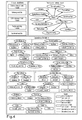
- FIG. 4 shows an object structure (top) as used by our system.
- the binding (gray lines) to the visual routines (rectangles) is shown, both feed-forward and feed-back.
- a dependency structure can be seen.
- the rectangles mark the bindings (gray lines) to visual routine variables.
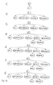
- FIG. 5 shows a (for simplicity not fully) resolved dependency tree for a world location property of an object. The path described below is marked.
- FIG. 6 illustrates a detection of a cyclic dependency at the retinal location node, which leads to a trace back of the path.
- a circular dependency can be resolved by cutting the branch between the retinal location and the spatial modulation map nodes.
- FIG. 7 shows how incorporating knowledge already acquired by the system changes the structure of the effective dependency graph and shrinks its size.
- FIG. 8 shows a mask of an object, which can be calculated by an algorithms.
- FIG. 9 on the left-hand side shows both the “hasProperty” and the “dependsOn” connectivity.
- On the right-hand side the pure structural definition (top) and the content of the long-term memory (bottom) is shown.
- FIG. 10 shows an update process for the color property of object 1 zoomed into the short-term memory with nodes currently resolving dependencies, nodes waiting on data to receive, nodes waiting on data to send and nodes finished sending data.
- FIG. 11 shows how arriving information (retinal size and region growing mask) travels along the dependency tree and triggers computations in their parent nodes with nodes that have finished receiving.
- FIG. 12 illustrates how the system requests a distance of the object. During this process, the existing information about the spatial modulation map gets reused, which reduces the computational demand dramatically.
- FIG. 13 shows the inventive system with its main components.
- FIG. 14 illustrates a conceptual and process memory.
- FIG. 15 shows a more detailed sketch of a visual input along with internal visual memories, stored in subnets for the conceptual memory and the memory of visual processes.
- FIG. 16 shows a program flow diagram
- Cognitive vision systems both technical and biological, with at least a minimal aim at generality have to carefully select the information they acquire from their environment.
- the system wants to measure which color an object is, it first needs to know where the object is and what retinal size it approximately has.
- Determining the position of an object might involve further processing which is again a dependency of the localization module and so on.
- the structure we have chosen allows modelling those dependencies along with the world knowledge the system has in a relational memory.
- the relational semantic memory proposed in [7] is used for representing information in the short- and long-term memory.
- This relational memory is, contrary to many other semantic memories, able to represent an arbitrary number of link patterns.
- classical link types like “hasProperty”, “isPartOf” or “isContainedIn” as shown in FIG. 1 can be defined.
- a sensory representation is stored in the property nodes to be able to later feed back that information into the system.
- a direct link to the visual routine used for acquiring a certain property is stored in the property nodes.
- an attached visual routine can be instructed (demanded) to deliver information.
- the objects in the memory are composed of several visual properties. Beside the classical link patterns, dependency patterns can be constructed.
- the dependency pattern that can be seen in FIG. 2 reads as “the measurement of A depends on operation op of B”. Given this link, we can measure A in a demand-driven way: if the system needs to measure node A, it knows it has to perform op of node B before being able to process A.
- the operation op of B has no further dependency and can thus be performed directly. Afterwards A can be measured. If the structures are getting more complex and the graph is getting deeper, a more sophisticated algorithm is needed to parse the graph. Details can be found below.
- each node has a state marking the validity of the node data. This is used to determine if the node information needs to be updated, i.e. if the visual routine bound to this node needs to be executed or not. Basically there are two states, as the data is either valid or invalid. In the beginning, all nodes contain invalid data. After updating, i.e. receiving information from a visual routine, the datum of the node is valid. The transition of the node's state back to invalid can be determined by time or any other criteria. Below it is shown how the state of the nodes are used to dynamically reduce the number of operations when a node with valid data is encountered.
- FIG. 4 shows the view on the object structure.
- the object properties are bound to the different visual routines (shown in the upper left).
- dependency patterns are shown in the lower part of FIG. 4 . Please note that the illustration only shows two different views on the memory content. Both representations coexist in the very same memory using the same nodes. As you can see, we only define the direct dependencies of the node and not the whole tree. This eases the design process, as it keeps the system structure manageable. The complete dependency tree will later be generated on the fly using the parsing algorithm described below.
- the measurement of e.g. the retinal location itself depends on sending a spatial modulation map ( 2 ).
- the dependency is optional, as the retinal location can also be measured without having a modulatory input.
- the sending of the spatial modulation map itself depends on the acquisition (receiving) of the spatial modulation map ( 3 ). This makes sense, as the modulatory information needs to be obtained before it can be used.
- Parsing the dependency graph can be formulated as a recursive problem. So the parsing algorithm is implemented as a recursive function, as can be seen in the pseudo-code below.
- the example is now continued and the dependencies are pursued one step further (see FIG. 6 ).
- the measurement of the spatial modulation map depends on the measurement of an object mask and on the measurement of the retinal location ( 4 ) of the object. These two information are necessary to create the spatial modulation map at the correct location with the correct shape.
- the retinal location node was already visited before. What is shown here is a loop or circular dependency, which would lead to a dead-lock situation if the system did not have means to deal with it.
- the first important point is to detect such circular dependencies which can be easily done by marking visited nodes in the graph and check if the node is already marked before entering it.
- the second important question is what to do once a circular dependency is detected.
- the dependency types described above come into play. After detecting a circular dependency, it is progressed back ( 4 ) to the parent node (spatial modulation map) and checked if the dependency is mandatory or optional. If the dependency is optional, we are done, as the loop at this point can be simply cut without breaking the algorithm. This is because the information that is missing is not essential for the algorithm to run. However, if the dependency is mandatory, the system cannot resolve the dependencies of the current node.
- the OR mode is interpreted by the graph parser as “only one of these dependencies is required”. To calculate the object mask one of these routines needs to be started. However, if the different algorithms are looked at, it can be seen that they differ in speed, initial requirements and accuracy.
- the retinal size estimation is very fast and only needs the object's location as an initial value, but is not very accurate.
- the region-growing is fast (but slower than the retinal size estimation), only needs the object's location as an initial value and is more accurate at least for homogeneously structured objects.
- the level-set method on the other hand is relatively slow compared to the other two algorithms, needs an initial segmentation to start, but is very accurate even for structured objects.
- the level-set method can never be used for initially estimating the object mask, because it needs an initial mask to run.
- the system should be able to select the algorithm that is as accurate as required, but as fast as possible. What is therefore required is a decision dependent on the current system's state (e.g. required accuracy and available time) and the system's knowledge (e.g. initial object mask).
- the parser now tries to resolve the dependencies consecutively until one of them can be resolved (a node can deny its execution if its initial conditions are not fulfilled).
- the pseudo-code of the graph parsing algorithm has a recursive nature as the problem is recursive.
- the algorithm dynamically generates the dependency graph starting from the requested property. It also needs to take into account the cyclic dependency detection and handling.
- the update procedure reads as follows:
- FIG. 9 The memory content of the system can be seen in FIG. 9 .
- prototypes the structure of an object is defined i.e. it is defined which properties constitute an object and how they relate.
- the proof-of-concept system we only use “hasProperty” links (black).
- the object structure is inherited and the dependency definitions and the bindings to the visual routines are added.
- the dependency structure originates from the direct dependency definition shown in FIG. 4 .
- the long-term memory inherits the object structure from the “SensoryInterface”. Here only the “hasProperty” links are shown to maintain readability. As can be seen, not all properties are instantiated per object (here only color and size are chosen). However, other nodes like retinal location or distance can be instantiated on demand.
- Property nodes in the long-term memory store sensory representations which are stable for the objects linked to them. Other more volatile object information is not stored there, but rather measured in a concrete scene and stored in the short-term memory.
- the content of the short-term memory inherits its structure from the long-term memory. To summarize, the object structure is propagated by inheritance through the different memory instances starting from the prototypical definitions down to the short-term memory.
- the representation is enriched by the bindings to the sensors and the graph linking nodes depending on each other.
- the binding and dependency graph is introduced in the “SensoryInterface” layer. Up to this point no real values are filled into the property nodes. This happens in the long-term memory for long-time stable sensor data that can be linked to one or more objects.
- the dependency resolving process and the subsequent information propagation process are implemented asynchronously.
- the first step to update a property is to instantiate it (see FIG. 10 a ).
- the properties up to the prototypical definitions are inherited.
- One of those properties are the dependencies of the node.
- To measure the colour of an object a spatial modulation map is needed, which in turn requires the retinal location of an object, which again needs weight factors for the saliency.
- the result of that propagation process is shown in FIG. 10 b.
- the weights for the saliency have no further dependency, they can be sent right away. After doing so, all dependencies of the retinal location node are fulfilled and it requests its visual routine for data (see FIG. 10 c ). After triggering the visual routine of the retinal location node, the process continues at the spatial modulation map. As defined previously (see FIG. 4 ), the modulation map requires an object mask to be processed.
- the object mask is an OR node, because three alternative measurement processes exist (retinal size estimation, region growing and a level-set method). Only one of these visual routines needs to run.
- the object mask node first tried to trigger the level-set measurement. However, as described above, this algorithm needs an initial mask to run. An alternative to having such a mask, so is to use a region growing method. Because the region growing node is the last leaf node, the dependencies is resolved by tracing back the dependency path while executing the node operations. This can be seen in FIG. 10 e to g . Finally, all marked nodes triggered their visual routine to deliver data. The spatial modulation map waits on data to send them.
- the visual routines When the data arrives from the visual routines, they get propagated upwards along the dependency tree. In FIG. 11 the retinal location and the mask of the region growing algorithm arrive (almost) simultaneously. The information about the region growing mask then travels upwards to the object mask where the processing can be finished. With a valid object mask and the retinal location of the object, a spatial modulation map can be computed and sent subsequently. After sending the spatial modulation map, the visual routine of the colour node runs and eventually returns the colour (see bottom of FIG. 11 ).
- Receiving the distance requires sending the spatial modulation map (see FIG. 4 ).
- sending this map requires the retrieval of the map, but in this case, the data of the spatial modulation map is still valid. Thus there is no need for updating and the process can continue with just sending out the information. If this procedure is compared to the procedure in FIG. 10 , where sending the spatial modulation map triggered the whole object mask and retinal location branch, the computational effort is reduced dramatically. Finally, the distance is requested and received by the system as shown at the bottom of FIG. 12 .
- the above presented system uses graph structures to represent both knowledge about functional dependencies and knowledge about the world in a consistent way.
- the fact that the relational semantic memory in our system can represent an arbitrary number of link patterns between nodes and is furthermore able to bind visual routines to its nodes.
- the modelling of dependency links are described and some modifiers for that link pattern are introduced, which allow to cover important use cases for vision systems.
- the cases of optional and mandatory information, different node operations modelling the direction of information flow and alternative pathways are discussed.
- a parsing algorithm based on the dependency link structure is layed out, which is able to detect and under certain circumstances “resolve” circular dependencies. Beyond this, the parsing algorithm is also able to efficiently reuse previously acquired sensory information and thus reduces the computational demand while keeping the full function of the system.
- the experiments show that with this framework allows to build systems that acquire data on demand and are able to flexibly adapt their processing chain.
- the system can estimate the costs of a certain action.
- the number of dependency nodes can be used as a cost function.
- the system learns which actions it can take if a time constraint applies.
- the system can furthermore learn how accurate and reliable a certain pathway is and use fast but coarse functions in cases where precise information is not necessary.
- the system may also try to find the dependencies itself and learn “optimal” processing queues.
- the invention furthermore provides a computer vision system that is driven by internal tasks that involve the resolution of visual subtasks by an active, semi-sequential recruitment and modulation of visual routines that selectively analyze the visual input.
- This recruitment and modulation occurs dynamically, during runtime, and is based not only on long-term knowledge about visual items and processes, but also on the currently available short-term information about a visual scene, its items and their properties compiled during immediately preceding steps of visual analysis.
- the long-term and the short-term memory might be structured as described above.
- the system with its main components is shown in FIG. 13 .
- visual input is acquired and analyzed/pre-processed by a series of non-task-specific pre-processing stages.
- the visual input may comprise more than a single image, as it is e.g. the case for stereo or multi-camera arrangements, and may also be grey-scale, color or using other visual domains, like infrared.
- the pre-processing stages may involve e.g. normalization, contrast enhancement, edge and feature extraction and similar processes, with the property that they do not require a knowledge about the scene and its objects, i.e., they are unspecific and general.
- the exact type of pre-processing operations is not relevant for this invention so that in the following we will not detail this further.
- the output from the pre-processing stages is used by the “visual routines”, shown in FIG. 13 B.
- These are visual processes that are object or context specific, i.e., they depend on what is searched for and/or what is already known about a visual scene, i.e., what is stored in short-term memory about the current sensory context.
- the object or context specificity is communicated via top-down connections arriving from a visual memory (dashed arrow on the top right in FIG. 13 ); and it involves selection, steering and modulation of the visual routines using parameters derived from specific object or context memory.
- Examples for visual routines are the detection of object candidates by looking for specific features indicative of an object's presence, object-specific tracking, location-specific segmentation, etc.
- visual routines can be activated specifically for the fulfillment of their assigned basic visual subtask, so that in normal operation only a (nevertheless dynamically changing at runtime) subset of visual routines is activated at each time step.
- the steerable visual routines are at the heart of knowledge-based selective visual analysis and together with visual memory and control processes they provide a way to intelligently manage the computational resources in a general-purpose vision system.
- the visual routines are steered from and deliver their results to a memory stage shown in FIG. 13 C.
- the sensory information from different visual routines is compiled and put in relation to already existing information about the visual scene.
- the memory stage comprises three main constituent parts:
- the conceptual memory is used to represent characteristic patterns that appear in the sensory input and that can be related e.g. to visual templates, physical objects, visual surroundings (like rooms) or characteristic scenes (indoor, outdoor, . . . ). It is called conceptual because it stores information of what makes up a specific sensory concept.
- the concepts stored in conceptual memory are valid for a certain lifetime, spanning a continuum ranging from concepts that are assumed to be generally valid (“long-term”) and stable over time to concepts that represent a certain temporary measurement or hypothesis about sensory objects, and that is expected to change on a short timescale (“short-term”).
- Long-term conceptual memory would e.g. contain the information of what defines a car visually, i.e., that it has wheels as components which should be arranged in a special spatial configuration.
- short-term memory would e.g. represent the information of particular cars at a particular time steps, that have been detected from sensory input and that move in sensory space as well as in 3D world coordinates.
- the short-term memory of a sensory element “car” is a specialization of a long-term concept “car”, in the sense that it inherits many of its properties but has additional information related to the sensory characteristics of an actually measured car as well as information related to the current measurement processes (coupled to visual routines) engaged in gaining and updating the object-related sensory information.
- the memory of visual processes is used to represent information of how to measure certain sensory, and in particular visual, properties of items from the conceptual memory.
- the memory of visual processes comprises a representation of a systems own sensory apparatus and the possible actions that can be taken on it at the level of visual routines.
- links e.g. denote that the presence of certain visual properties or subparts (the wheels of the car) is a good indication for a more global pattern concept (the car).
- the nodes additionally contain internal parameters associated with current sensory measurements (e.g. the position, colour, etc. of an object) together with confidences as well as parameters needed for driving visual processes and the visual routines.
- current sensory measurements e.g. the position, colour, etc. of an object
- FIG. 15 shows a more detailed sketch of a visual input along with the internal visual memories, stored in subnets for the conceptual memory and the memory of visual processes.
- the conceptual memory contains the concept of the car in a hierarchical graph, e.g. by specifying which parts like lights, wheels, windows, visual appearance, etc. a car should have.
- the memory of visual processes encodes how to measure e.g. the presence of these parts by accessing the corresponding visual routines, like specialized wheel detecting modules.
- the conceptualized car may contain information such as e.g. the expected relative position where certain car parts are expected to be found, or which features would make it easy to detect them (such as a red colour for the rear light).
- This information is then selectively passed down towards the visual routines, which can make use of it to constrain and improve their function. For example, if the front wheel of the car has already been detected and therefore the rear wheel is expected to be found in a certain area, the visual routine in charge of detecting it can be constrained to search only in this area, making the search cheaper and the results more robust.
- Both the long- and the short-term memory of the system are updated dynamically during runtime.
- the updating includes parameter values stored in the nodes of the graphs as well as the creation, modification and destruction of graph structures.
- New graph structures appear e.g. when new sensory items are included into the short-term memory (for example if visual routines indicate an item pop-out because it is very salient, like a moving object against a stationary background), or when already detected sensory items are combined to form larger conceptual compounds (for example when two wheels have been detected and are then bound to a new conceptual node representing the sensory detection of a car).
- Graph structures can be destroyed when their sensory validity is no longer given, e.g. when an item vanishes from the scene and is not expected to reappear.
- the control module controls the information flow between the conceptual memory, the memory of visual processes and the visual routines. It continuously identifies sets of nodes with parameters that should be updated or measured.
- the control module can link the parameters to the processes necessary to measure them. Therefore, the goal to measure a parameter is equivalent to a visual task, like finding out whether a certain object is actually present in a scene or what is its location, colour, etc. In short, the control module makes use of the process memory in combination with the currently available conceptual memory to decide how to measure the required parameters.
- a memory-based selective scheme alleviates the resource problem and postulates vision as a hypothesis-driven, guided search process.
- Hierarchical representations as provided by the graph-based memory structure can reduce the processing resources even further, resulting in a coarse-to-fine search.
- a restriction to only those visual routines and parameter regimes that are necessary for a given task increases the robustness and reliability of measurement results.
- the control module uses different hints to select, steer and modulate the visual routines that are necessary for a visual task. It uses information stored in the links related to the memory of visual processes to check for the expected information gain and costs when performing particular sensory events and for dependencies between the sensory events (see FIG. 14 B bottom, dashed arrows) and their link to visual routines (see FIG. 15 bottom).
- dependency links are used with different qualifiers/link types, leading to a different effect of the processing order and the information flow. Used types were. “mandatory”, “optional” and “one-of-many”.
- a strict order is imposed between the two connected nodes, so that the processing of one node first requires valid results of a dependent node, rendering it necessary that the dependent node is processed first.
- a processing node can make use of the results of a dependent node, if the dependent node has access to valid information, but ignore it otherwise.
- the dependency is resolved as soon as one of several dependent nodes has achieved a valid result.
- the dependency information is used together with the current state of the already compiled sensory information to determine the processing order of visual subtasks.
- information about expected gain and costs are taken into consideration, so that the control module can decide e.g. if it wants to get approximate results with low or accurate results with higher processing costs.
- uncertainty information is available (attached to the process memory and the sensory measurements), probabilistic methods that work on graphical structures can be included here.
- Each node representing a sensory event keeps track of the validity of its results. This validity can be determined e.g. by a confidence of the measurement, the quality of the gained data or the time passed since its last measurement.
- the control module allows dependencies of the visual subtasks to be resolved automatically.
- This is shown as a program flow diagram in FIG. 16 and comprises the steps of iteratively traversing the graph depending on the information from the memory of visual processes, the expected gain and cost as well as the validity of the results.
- the conceptual memory especially the short-term sensory memory, is used to store what has already been inspected and to serve as parameters for the context—(i.e., conceptual memory)—dependent visual routines.
- the iterative graph traversal at some point arrives at nodes that are linked to visual routines (as shown in FIG. 15 bottom right), triggering a specific visual analysis.
- a visual routine delivers a result, its validity is checked by the attached memory node and communicated further to the predecessor node that called it. In this way, the necessary sensory processes are triggered and the dependencies of a visual task are solved.
- the invention can also be summarized as
Landscapes
- Engineering & Computer Science (AREA)
- Physics & Mathematics (AREA)
- General Physics & Mathematics (AREA)
- Multimedia (AREA)
- Theoretical Computer Science (AREA)
- Computer Vision & Pattern Recognition (AREA)
- Software Systems (AREA)
- Image Analysis (AREA)
Applications Claiming Priority (6)
| Application Number | Priority Date | Filing Date | Title |
|---|---|---|---|
| EP09153896.7 | 2009-02-27 | ||
| EP09153896 | 2009-02-27 | ||
| EP09153896 | 2009-02-27 | ||
| EP10151739 | 2010-01-27 | ||
| EP10151739.9 | 2010-01-27 | ||
| EP10151739A EP2224371A1 (en) | 2009-02-27 | 2010-01-27 | Artificial vision system and method for knowledge-based selective visual analysis |
Publications (2)
| Publication Number | Publication Date |
|---|---|
| US20100223216A1 US20100223216A1 (en) | 2010-09-02 |
| US8433661B2 true US8433661B2 (en) | 2013-04-30 |
Family
ID=42102201
Family Applications (1)
| Application Number | Title | Priority Date | Filing Date |
|---|---|---|---|
| US12/711,292 Expired - Fee Related US8433661B2 (en) | 2009-02-27 | 2010-02-24 | Artificial vision system and method for knowledge-based selective visual analysis |
Country Status (3)
| Country | Link |
|---|---|
| US (1) | US8433661B2 (enExample) |
| EP (1) | EP2224371A1 (enExample) |
| JP (1) | JP5249969B2 (enExample) |
Cited By (4)
| Publication number | Priority date | Publication date | Assignee | Title |
|---|---|---|---|---|
| US20150006501A1 (en) * | 2013-06-26 | 2015-01-01 | Google Inc. | Discovering entity actions for an entity graph |
| US9715657B2 (en) | 2013-01-09 | 2017-07-25 | Canon Kabushiki Kaisha | Information processing apparatus, generating method, medical diagnosis support apparatus, and medical diagnosis support method |
| US10713261B2 (en) | 2013-03-13 | 2020-07-14 | Google Llc | Generating insightful connections between graph entities |
| US12007784B2 (en) | 2020-03-26 | 2024-06-11 | Here Global B.V. | Method and apparatus for self localization |
Families Citing this family (33)
| Publication number | Priority date | Publication date | Assignee | Title |
|---|---|---|---|---|
| WO2012129371A2 (en) | 2011-03-22 | 2012-09-27 | Nant Holdings Ip, Llc | Reasoning engines |
| US9269063B2 (en) | 2011-09-23 | 2016-02-23 | Elwha Llc | Acquiring and transmitting event related tasks and subtasks to interface devices |
| US20130081050A1 (en) * | 2011-09-23 | 2013-03-28 | Elwha LLC, a limited liability company of the State of Delaware | Acquiring and transmitting tasks and subtasks to interface devices |
| CN102857363B (zh) * | 2012-05-04 | 2016-04-20 | 运软网络科技(上海)有限公司 | 一种虚拟网络的自主管理系统和方法 |
| US10115248B2 (en) * | 2013-03-14 | 2018-10-30 | Ebay Inc. | Systems and methods to fit an image of an inventory part |
| CN110431037B (zh) * | 2017-02-10 | 2022-11-29 | 日产北美公司 | 包括运用部分可观察马尔可夫决策过程模型示例的自主车辆操作管理 |
| US11586960B2 (en) * | 2017-05-09 | 2023-02-21 | Visa International Service Association | Autonomous learning platform for novel feature discovery |
| US11316865B2 (en) | 2017-08-10 | 2022-04-26 | Nuance Communications, Inc. | Ambient cooperative intelligence system and method |
| US20190051376A1 (en) | 2017-08-10 | 2019-02-14 | Nuance Communications, Inc. | Automated clinical documentation system and method |
| WO2019089015A1 (en) | 2017-10-31 | 2019-05-09 | Nissan North America, Inc. | Autonomous vehicle operation with explicit occlusion reasoning |
| WO2020204871A1 (en) | 2017-12-22 | 2020-10-08 | Nissan North America, Inc. | Shared autonomous vehicle operational management |
| US11250382B2 (en) | 2018-03-05 | 2022-02-15 | Nuance Communications, Inc. | Automated clinical documentation system and method |
| US20190272895A1 (en) | 2018-03-05 | 2019-09-05 | Nuance Communications, Inc. | System and method for review of automated clinical documentation |
| EP3762921A4 (en) | 2018-03-05 | 2022-05-04 | Nuance Communications, Inc. | AUTOMATED CLINICAL DOCUMENTATION SYSTEM AND PROCESS |
| US11216480B2 (en) | 2019-06-14 | 2022-01-04 | Nuance Communications, Inc. | System and method for querying data points from graph data structures |
| US11043207B2 (en) | 2019-06-14 | 2021-06-22 | Nuance Communications, Inc. | System and method for array data simulation and customized acoustic modeling for ambient ASR |
| US11227679B2 (en) | 2019-06-14 | 2022-01-18 | Nuance Communications, Inc. | Ambient clinical intelligence system and method |
| US11531807B2 (en) | 2019-06-28 | 2022-12-20 | Nuance Communications, Inc. | System and method for customized text macros |
| US11670408B2 (en) | 2019-09-30 | 2023-06-06 | Nuance Communications, Inc. | System and method for review of automated clinical documentation |
| US11635758B2 (en) | 2019-11-26 | 2023-04-25 | Nissan North America, Inc. | Risk aware executor with action set recommendations |
| US11899454B2 (en) | 2019-11-26 | 2024-02-13 | Nissan North America, Inc. | Objective-based reasoning in autonomous vehicle decision-making |
| US11613269B2 (en) | 2019-12-23 | 2023-03-28 | Nissan North America, Inc. | Learning safety and human-centered constraints in autonomous vehicles |
| US11300957B2 (en) | 2019-12-26 | 2022-04-12 | Nissan North America, Inc. | Multiple objective explanation and control interface design |
| US11714971B2 (en) | 2020-01-31 | 2023-08-01 | Nissan North America, Inc. | Explainability of autonomous vehicle decision making |
| US11577746B2 (en) | 2020-01-31 | 2023-02-14 | Nissan North America, Inc. | Explainability of autonomous vehicle decision making |
| US11782438B2 (en) | 2020-03-17 | 2023-10-10 | Nissan North America, Inc. | Apparatus and method for post-processing a decision-making model of an autonomous vehicle using multivariate data |
| US12165073B2 (en) * | 2020-04-28 | 2024-12-10 | Leela AI, Inc. | Computer vision learning system |
| CN112040002B (zh) * | 2020-09-07 | 2023-04-18 | 广东电网有限责任公司电力调度控制中心 | 一种基于配电云平台的数据融合方法、装置及设备 |
| US11222103B1 (en) | 2020-10-29 | 2022-01-11 | Nuance Communications, Inc. | Ambient cooperative intelligence system and method |
| US11478927B1 (en) * | 2021-04-01 | 2022-10-25 | Giant.Ai, Inc. | Hybrid computing architectures with specialized processors to encode/decode latent representations for controlling dynamic mechanical systems |
| WO2023164069A1 (en) | 2022-02-24 | 2023-08-31 | Leela AI, Inc. | Methods and systems for training and execution of improved learning systems for identification of components in time-based data streams |
| US11803478B1 (en) * | 2022-10-19 | 2023-10-31 | Inductive Automation, LLC | Controlled activation of interdependent bindings |
| CN120493082B (zh) * | 2025-07-21 | 2025-09-12 | 深圳适创腾扬科技有限公司 | 一种结合压铸流程优先级的压铸参数调优方法及相关装置 |
Citations (2)
| Publication number | Priority date | Publication date | Assignee | Title |
|---|---|---|---|---|
| US20070179918A1 (en) | 2006-02-02 | 2007-08-02 | Bernd Heisele | Hierarchical system for object recognition in images |
| US20100083109A1 (en) * | 2008-09-29 | 2010-04-01 | Smart Technologies Ulc | Method for handling interactions with multiple users of an interactive input system, and interactive input system executing the method |
Family Cites Families (1)
| Publication number | Priority date | Publication date | Assignee | Title |
|---|---|---|---|---|
| JPH08145738A (ja) * | 1994-11-18 | 1996-06-07 | Fujitsu Ltd | 能動的認識装置 |
-
2010
- 2010-01-27 EP EP10151739A patent/EP2224371A1/en not_active Withdrawn
- 2010-02-16 JP JP2010030845A patent/JP5249969B2/ja active Active
- 2010-02-24 US US12/711,292 patent/US8433661B2/en not_active Expired - Fee Related
Patent Citations (2)
| Publication number | Priority date | Publication date | Assignee | Title |
|---|---|---|---|---|
| US20070179918A1 (en) | 2006-02-02 | 2007-08-02 | Bernd Heisele | Hierarchical system for object recognition in images |
| US20100083109A1 (en) * | 2008-09-29 | 2010-04-01 | Smart Technologies Ulc | Method for handling interactions with multiple users of an interactive input system, and interactive input system executing the method |
Non-Patent Citations (6)
| Title |
|---|
| Borji, Ali et al., "Learning Object-Based Attention Control", XP-002579569, Dec. 12, 2008, pp. 1-7. |
| Borji, Ali, "Interactive Learning of Task-Driven Visual Attention Control", Ph.D. Thesis, School of Cognitive Sciences, XP-002579570, 2009, pp. 1-162. |
| Draper, Bruce A., "Learning Object Recognition Strategies", Ph.D. Thesis, Department of Computer Sciences, University of Massachusetts, XP-002579571, May 1993, 167 pages. |
| European Search Report application No. 10151739.9 dated Jun. 9, 2010. |
| Navalpakkam, Vidhya et al., "Modeling the Influence of Task on Attention", Vision Research, vol. 45, No. 2, 2005, pp. 205-231. |
| Rohrbein, Florian et al., "Bayesian Columnar Networks for Grounded Cognitive Systems", 30th Annual Meeting of the Cognitive Science Society, XP-002579572, Jun. 23, 2008, pp. 1423-1429. |
Cited By (5)
| Publication number | Priority date | Publication date | Assignee | Title |
|---|---|---|---|---|
| US9715657B2 (en) | 2013-01-09 | 2017-07-25 | Canon Kabushiki Kaisha | Information processing apparatus, generating method, medical diagnosis support apparatus, and medical diagnosis support method |
| US10713261B2 (en) | 2013-03-13 | 2020-07-14 | Google Llc | Generating insightful connections between graph entities |
| US20150006501A1 (en) * | 2013-06-26 | 2015-01-01 | Google Inc. | Discovering entity actions for an entity graph |
| US9235653B2 (en) * | 2013-06-26 | 2016-01-12 | Google Inc. | Discovering entity actions for an entity graph |
| US12007784B2 (en) | 2020-03-26 | 2024-06-11 | Here Global B.V. | Method and apparatus for self localization |
Also Published As
| Publication number | Publication date |
|---|---|
| EP2224371A1 (en) | 2010-09-01 |
| JP2010262625A (ja) | 2010-11-18 |
| US20100223216A1 (en) | 2010-09-02 |
| JP5249969B2 (ja) | 2013-07-31 |
Similar Documents
| Publication | Publication Date | Title |
|---|---|---|
| US8433661B2 (en) | Artificial vision system and method for knowledge-based selective visual analysis | |
| US11663474B1 (en) | Artificially intelligent systems, devices, and methods for learning and/or using a device's circumstances for autonomous device operation | |
| Chen et al. | Semantic visual simultaneous localization and mapping: A survey | |
| JP7192143B2 (ja) | オンライン学習を利用した物体追跡のための方法およびシステム | |
| KR102664916B1 (ko) | 익스플레이너블 셀프-포커스드 어텐션을 이용하여 행동 예측을 수행하는 방법 및 장치 | |
| Kusmenko et al. | Highly-optimizing and multi-target compiler for embedded system models: C++ compiler toolchain for the component and connector language EmbeddedMontiArc | |
| Toschi et al. | Characterizing perception module performance and robustness in production-scale autonomous driving system | |
| Nieto et al. | Optimising computer vision based ADAS: vehicle detection case study | |
| Benrachou et al. | Improving efficiency and generalisability of motion predictions with deep multi-agent learning and multi-head attention | |
| KR102324804B1 (ko) | 영상 내 객체의 컨텍스트 정보 생성을 통한 모니터링 시스템 | |
| CN120011898B (zh) | 无人机定位跟踪风险识别方法、存储介质及应用 | |
| CN114548237A (zh) | 一种人机交互的多模态数据融合方法、装置及设备 | |
| Fickenscher et al. | DSL-based acceleration of automotive environment perception and mapping algorithms for embedded CPUs, GPUs, and FPGAs | |
| CN117173676A (zh) | 一种驾驶员的变道意图识别方法、装置、设备及介质 | |
| WO2023044661A1 (en) | Learning reliable keypoints in situ with introspective self-supervision | |
| de Souza Muñoz et al. | Pignaton de Freitas | |
| Rebhan et al. | Consistent modeling of functional dependencies along with world knowledge | |
| Ali et al. | Memorability-based multimedia analytics for robotic interestingness prediction system using trimmed Q-learning algorithm | |
| Sakabe et al. | An episode tracker for cognitive architectures | |
| CN112989352A (zh) | 用于基于模型的分析的方法和设备 | |
| Jyothi et al. | Real time smart object detection using machine learning | |
| Hicks et al. | Self Driving Robot Car | |
| Huang | Real-time Pedestrian Classification System Using Deep Learning on a Raspberry Pi Cluster | |
| Clement | Multimodal RGB-D Autonomous Agents Steered by Deep Neural Networks | |
| Fickenscher et al. | Environment Perception and Mapping Algorithms for Embedded CPUs, GPUs |
Legal Events
| Date | Code | Title | Description |
|---|---|---|---|
| AS | Assignment |
Owner name: HONDA RESEARCH INSTITUTE EUROPE GMBH, GERMANY Free format text: ASSIGNMENT OF ASSIGNORS INTEREST;ASSIGNORS:EGGERT, JULIAN;REBHAN, SVEN;REEL/FRAME:023981/0777 Effective date: 20100217 |
|
| STCF | Information on status: patent grant |
Free format text: PATENTED CASE |
|
| FEPP | Fee payment procedure |
Free format text: PAYOR NUMBER ASSIGNED (ORIGINAL EVENT CODE: ASPN); ENTITY STATUS OF PATENT OWNER: LARGE ENTITY |
|
| FPAY | Fee payment |
Year of fee payment: 4 |
|
| FEPP | Fee payment procedure |
Free format text: MAINTENANCE FEE REMINDER MAILED (ORIGINAL EVENT CODE: REM.); ENTITY STATUS OF PATENT OWNER: LARGE ENTITY |
|
| LAPS | Lapse for failure to pay maintenance fees |
Free format text: PATENT EXPIRED FOR FAILURE TO PAY MAINTENANCE FEES (ORIGINAL EVENT CODE: EXP.); ENTITY STATUS OF PATENT OWNER: LARGE ENTITY |
|
| STCH | Information on status: patent discontinuation |
Free format text: PATENT EXPIRED DUE TO NONPAYMENT OF MAINTENANCE FEES UNDER 37 CFR 1.362 |
|
| FP | Lapsed due to failure to pay maintenance fee |
Effective date: 20210430 |