US8425164B2 - Method and device for balancing a tool coupling - Google Patents
Method and device for balancing a tool coupling Download PDFInfo
- Publication number
- US8425164B2 US8425164B2 US12/515,982 US51598207A US8425164B2 US 8425164 B2 US8425164 B2 US 8425164B2 US 51598207 A US51598207 A US 51598207A US 8425164 B2 US8425164 B2 US 8425164B2
- Authority
- US
- United States
- Prior art keywords
- imbalance
- tool
- tool coupling
- recesses
- face
- Prior art date
- Legal status (The legal status is an assumption and is not a legal conclusion. Google has not performed a legal analysis and makes no representation as to the accuracy of the status listed.)
- Active, expires
Links
Images


Classifications
-
- B—PERFORMING OPERATIONS; TRANSPORTING
- B23—MACHINE TOOLS; METAL-WORKING NOT OTHERWISE PROVIDED FOR
- B23B—TURNING; BORING
- B23B31/00—Chucks; Expansion mandrels; Adaptations thereof for remote control
- B23B31/006—Conical shanks of tools
-
- G—PHYSICS
- G01—MEASURING; TESTING
- G01M—TESTING STATIC OR DYNAMIC BALANCE OF MACHINES OR STRUCTURES; TESTING OF STRUCTURES OR APPARATUS, NOT OTHERWISE PROVIDED FOR
- G01M1/00—Testing static or dynamic balance of machines or structures
- G01M1/30—Compensating imbalance
- G01M1/32—Compensating imbalance by adding material to the body to be tested, e.g. by correcting-weights
-
- G—PHYSICS
- G01—MEASURING; TESTING
- G01M—TESTING STATIC OR DYNAMIC BALANCE OF MACHINES OR STRUCTURES; TESTING OF STRUCTURES OR APPARATUS, NOT OTHERWISE PROVIDED FOR
- G01M1/00—Testing static or dynamic balance of machines or structures
- G01M1/30—Compensating imbalance
- G01M1/34—Compensating imbalance by removing material from the body to be tested, e.g. from the tread of tyres
-
- B—PERFORMING OPERATIONS; TRANSPORTING
- B23—MACHINE TOOLS; METAL-WORKING NOT OTHERWISE PROVIDED FOR
- B23B—TURNING; BORING
- B23B2231/00—Details of chucks, toolholder shanks or tool shanks
- B23B2231/10—Chucks having data storage chips
-
- B—PERFORMING OPERATIONS; TRANSPORTING
- B23—MACHINE TOOLS; METAL-WORKING NOT OTHERWISE PROVIDED FOR
- B23B—TURNING; BORING
- B23B2250/00—Compensating adverse effects during turning, boring or drilling
- B23B2250/04—Balancing rotating components
-
- B—PERFORMING OPERATIONS; TRANSPORTING
- B23—MACHINE TOOLS; METAL-WORKING NOT OTHERWISE PROVIDED FOR
- B23B—TURNING; BORING
- B23B2250/00—Compensating adverse effects during turning, boring or drilling
- B23B2250/16—Damping of vibrations
-
- Y—GENERAL TAGGING OF NEW TECHNOLOGICAL DEVELOPMENTS; GENERAL TAGGING OF CROSS-SECTIONAL TECHNOLOGIES SPANNING OVER SEVERAL SECTIONS OF THE IPC; TECHNICAL SUBJECTS COVERED BY FORMER USPC CROSS-REFERENCE ART COLLECTIONS [XRACs] AND DIGESTS
- Y10—TECHNICAL SUBJECTS COVERED BY FORMER USPC
- Y10T—TECHNICAL SUBJECTS COVERED BY FORMER US CLASSIFICATION
- Y10T408/00—Cutting by use of rotating axially moving tool
- Y10T408/76—Tool-carrier with vibration-damping means
-
- Y—GENERAL TAGGING OF NEW TECHNOLOGICAL DEVELOPMENTS; GENERAL TAGGING OF CROSS-SECTIONAL TECHNOLOGIES SPANNING OVER SEVERAL SECTIONS OF THE IPC; TECHNICAL SUBJECTS COVERED BY FORMER USPC CROSS-REFERENCE ART COLLECTIONS [XRACs] AND DIGESTS
- Y10—TECHNICAL SUBJECTS COVERED BY FORMER USPC
- Y10T—TECHNICAL SUBJECTS COVERED BY FORMER US CLASSIFICATION
- Y10T408/00—Cutting by use of rotating axially moving tool
- Y10T408/94—Tool-support
-
- Y—GENERAL TAGGING OF NEW TECHNOLOGICAL DEVELOPMENTS; GENERAL TAGGING OF CROSS-SECTIONAL TECHNOLOGIES SPANNING OVER SEVERAL SECTIONS OF THE IPC; TECHNICAL SUBJECTS COVERED BY FORMER USPC CROSS-REFERENCE ART COLLECTIONS [XRACs] AND DIGESTS
- Y10—TECHNICAL SUBJECTS COVERED BY FORMER USPC
- Y10T—TECHNICAL SUBJECTS COVERED BY FORMER US CLASSIFICATION
- Y10T409/00—Gear cutting, milling, or planing
- Y10T409/30—Milling
- Y10T409/303752—Process
-
- Y—GENERAL TAGGING OF NEW TECHNOLOGICAL DEVELOPMENTS; GENERAL TAGGING OF CROSS-SECTIONAL TECHNOLOGIES SPANNING OVER SEVERAL SECTIONS OF THE IPC; TECHNICAL SUBJECTS COVERED BY FORMER USPC CROSS-REFERENCE ART COLLECTIONS [XRACs] AND DIGESTS
- Y10—TECHNICAL SUBJECTS COVERED BY FORMER USPC
- Y10T—TECHNICAL SUBJECTS COVERED BY FORMER US CLASSIFICATION
- Y10T409/00—Gear cutting, milling, or planing
- Y10T409/30—Milling
- Y10T409/304312—Milling with means to dampen vibration
-
- Y—GENERAL TAGGING OF NEW TECHNOLOGICAL DEVELOPMENTS; GENERAL TAGGING OF CROSS-SECTIONAL TECHNOLOGIES SPANNING OVER SEVERAL SECTIONS OF THE IPC; TECHNICAL SUBJECTS COVERED BY FORMER USPC CROSS-REFERENCE ART COLLECTIONS [XRACs] AND DIGESTS
- Y10—TECHNICAL SUBJECTS COVERED BY FORMER USPC
- Y10T—TECHNICAL SUBJECTS COVERED BY FORMER US CLASSIFICATION
- Y10T409/00—Gear cutting, milling, or planing
- Y10T409/30—Milling
- Y10T409/30952—Milling with cutter holder
Definitions
- the invention relates to a method for balancing a tool coupling, and tool couplings balanced by means of this method.
- EP 1 007 256 describes a tool carrier in which compensating bores are provided in the radial area arranged in the interior of the coupling.
- FIGS. 1 and 2 show perspective diagrams of hollow shank taper (HSK) tool couplings according to the prior art
- FIG. 3-8 show various embodiments of hollow shank tapers of tool couplings according to the invention
- the hollow shank taper (HSK) tool coupling shown in FIG. 1 has the known recesses, i.e. notches 1 , bores 2 , etc, which are required for gripping, positioning, etc, for example in the case of automatic tool change. These recesses are as a rule differently dimensioned on opposite sides and therefore produce imbalance. For compensating this imbalance, it is usual to remove material, generally in the form of bores 3 , as far as possible in the vicinity of the producer of the imbalance.
- This method of compensating imbalance compensates the static imbalance but not the dynamic imbalance which leads to a tumbling movement of the tool coupling at relatively high speeds.
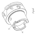
- the most frequent originators of the imbalance are shown, namely the two recesses 4 opposite one another and located in the end face 9 of the tool coupling for connection to the machine spindle and transmission of the drive torque, and positioning grooves 5 and a bore provided in the opposite side, i.e. not visible in the figure and intended for a chip (electronic data acquisition) in the flange 7 connecting to the taper surface 6 .
- the imbalance at the end face which is due to the recesses 4 , is compensated by bores 8 in the end face 9 of the tool coupling, i.e. in the axial plane of the imbalance generation.
- the recesses present in the flange 7 are likewise compensated in the same axial plane of the imbalance generation, i.e. by bores.
- additional compensation bores 10 are arranged in the recesses 4 themselves.
- FIG. 5 shows the arrangement of additional slots in the recesses 4 themselves.
- the bores 8 can be provided with cylindrical inserts 12 . This prevents the penetration of dirt and permits scanning of the surfaces provided with compensation bores for measurement purposes.
- the inserts 12 consist of a material of lower density, for example of plastics, light metals or hollow bodies.
- FIG. 8 shows how slots 11 introduced for compensation are closed with appropriately shaped inserts 13 .
Landscapes
- Physics & Mathematics (AREA)
- General Physics & Mathematics (AREA)
- Engineering & Computer Science (AREA)
- Mechanical Engineering (AREA)
- Testing Of Balance (AREA)
- Jigs For Machine Tools (AREA)
- Constituent Portions Of Griding Lathes, Driving, Sensing And Control (AREA)
Abstract
Description
Claims (4)
Applications Claiming Priority (3)
| Application Number | Priority Date | Filing Date | Title |
|---|---|---|---|
| CH19792006 | 2006-12-06 | ||
| CH1979/06 | 2006-12-06 | ||
| PCT/CH2007/000608 WO2008067683A1 (en) | 2006-12-06 | 2007-12-03 | Method and device for balancing a tool coupling |
Publications (2)
| Publication Number | Publication Date |
|---|---|
| US20100061822A1 US20100061822A1 (en) | 2010-03-11 |
| US8425164B2 true US8425164B2 (en) | 2013-04-23 |
Family
ID=38328233
Family Applications (1)
| Application Number | Title | Priority Date | Filing Date |
|---|---|---|---|
| US12/515,982 Active 2029-01-17 US8425164B2 (en) | 2006-12-06 | 2007-12-03 | Method and device for balancing a tool coupling |
Country Status (7)
| Country | Link |
|---|---|
| US (1) | US8425164B2 (en) |
| EP (2) | EP2099577B1 (en) |
| JP (1) | JP5352467B2 (en) |
| CN (1) | CN101553335A (en) |
| ES (1) | ES2407658T3 (en) |
| PL (1) | PL2099577T3 (en) |
| WO (1) | WO2008067683A1 (en) |
Cited By (3)
| Publication number | Priority date | Publication date | Assignee | Title |
|---|---|---|---|---|
| US20150321265A1 (en) * | 2013-02-14 | 2015-11-12 | Daido Steel Co., Ltd. | Collet |
| US20160082520A1 (en) * | 2014-09-22 | 2016-03-24 | Hyundai Motor Company | Boring device |
| US11097352B2 (en) * | 2019-07-15 | 2021-08-24 | Algra S.P.A. | Device for the quick change of tool holder adapters |
Families Citing this family (13)
| Publication number | Priority date | Publication date | Assignee | Title |
|---|---|---|---|---|
| US20110085871A1 (en) * | 2009-10-13 | 2011-04-14 | Kennametal Inc. | Coupling Mechanism For Connecting A Toolholder Assembly And A Machine Tool |
| US9645551B2 (en) | 2011-12-22 | 2017-05-09 | The Swatch Group Research And Development Ltd | Method of improving the pivoting of a wheel set |
| EP2607970B1 (en) * | 2011-12-22 | 2018-02-07 | The Swatch Group Research and Development Ltd. | Method for improving the pivoting of a mobile device |
| DE102013020597B3 (en) * | 2013-12-13 | 2014-10-30 | FMB Maschinenbaugesellschaft | Balancing device for a bar loading magazine |
| CN104385017B (en) * | 2014-09-24 | 2016-08-24 | 北京机电院机床有限公司 | For the automatic loading/unloading pallet of blade processing lathe and with clamping method |
| CN104500606A (en) * | 2014-11-18 | 2015-04-08 | 四川邮科通信技术有限公司 | Drum type gear coupling |
| EP3050654B1 (en) | 2015-01-30 | 2022-03-23 | Sandvik Intellectual Property AB | Tool including dummy chip |
| FR3037518B1 (en) * | 2015-06-22 | 2017-12-29 | Seco-E P B | TOOL HOLDER ADAPTED TO ENABLE BALANCED ADJUSTMENT |
| DE102017108719A1 (en) * | 2017-04-24 | 2018-10-25 | Gühring KG | Method for assembling a tool system module and accordingly manufactured tool system module |
| CN107806960B (en) * | 2017-10-11 | 2019-07-02 | 中国航发南方工业有限公司 | Balance weight and duplicate removal balance method for flexible rotor dynamic balance |
| DE102017125889A1 (en) * | 2017-11-06 | 2019-05-09 | Thyssenkrupp Ag | Method and device for balancing |
| CN112238227B (en) * | 2019-07-17 | 2024-07-30 | 肯纳金属公司 | Cutting tool holder with improved damping effect |
| US20240326193A1 (en) * | 2021-09-07 | 2024-10-03 | Fuzhun Precision Tooling (Jiashan) Co., Ltd. | Numerical control tool holder, rotary body dynamic balance detection and correction device, and method |
Citations (24)
| Publication number | Priority date | Publication date | Assignee | Title |
|---|---|---|---|---|
| JPS4954879U (en) * | 1972-08-18 | 1974-05-15 | ||
| JPS642813A (en) * | 1987-03-12 | 1989-01-06 | Entwicklungszentrum Fuer Zerspannungstechnik | Cutter head |
| US4955767A (en) * | 1987-07-20 | 1990-09-11 | Heinz Kaiser Ag | Boring attachment |
| US5074723A (en) | 1989-04-13 | 1991-12-24 | Kennametal Inc. | Method and apparatus for balancing a rotary tool assembly |
| US5116194A (en) * | 1990-05-15 | 1992-05-26 | E.P.B. Emile Pfalzgraf, S.A. | Boring head |
| JPH05177495A (en) * | 1991-12-28 | 1993-07-20 | Daishowa Seiki Co Ltd | Tool holder |
| US5407308A (en) * | 1991-12-04 | 1995-04-18 | Kitamura Machinery Co., Ltd. | Tool holder coupling apparatus |
| WO1998031494A1 (en) | 1997-01-17 | 1998-07-23 | Sandvik Aktiebolag (Publ) | Tool carrier |
| DE29809653U1 (en) | 1998-05-29 | 1998-08-13 | Marciniak, Heinz, 58455 Witten | Tool holder, especially for milling tools |
| US5810527A (en) * | 1994-03-29 | 1998-09-22 | Kennametal Hertal Ag | Rotary tool with balancing rings |
| JPH1128633A (en) * | 1997-07-07 | 1999-02-02 | Nikken Kosakusho:Kk | Tool holder |
| JPH11104931A (en) * | 1997-10-01 | 1999-04-20 | Nt Tool Kk | Tool holder |
| JP2000042857A (en) * | 1998-07-27 | 2000-02-15 | Hiromitsu Toyomoto | Holding tool |
| JP2000084783A (en) * | 1998-09-16 | 2000-03-28 | Manyoo Tool Kk | Tool holder |
| US6135684A (en) * | 1998-12-04 | 2000-10-24 | Manyo Tool Kabushiki Kaisha | Tool holder |
| DE19920699C2 (en) | 1999-05-05 | 2001-10-31 | Hofmann Mess Und Auswuchttechn | Method and device for balancing rotors |
| JP2002066855A (en) * | 2000-05-08 | 2002-03-05 | Shigeru Umemoto | Rotating tool holding device and head removal jig |
| US6364581B2 (en) * | 1998-10-08 | 2002-04-02 | Baladyne Corporation | Balancer |
| US20030033873A1 (en) | 2001-08-20 | 2003-02-20 | Rego-Fix Ag. | Balancing system for compensating for unbalance of a rotating machine part |
| US6557445B1 (en) * | 1999-08-30 | 2003-05-06 | Nt Tool Kabushiki Kaisha | Tool holder and a runout correcting tool for a tool holder |
| JP2004009244A (en) * | 2002-06-10 | 2004-01-15 | Nikken Kosakusho Works Ltd | Tool holder |
| JP2005305600A (en) * | 2004-04-22 | 2005-11-04 | Mitsubishi Materials Corp | Boring bar and processing method thereof |
| JP2005329509A (en) * | 2004-05-20 | 2005-12-02 | Tungaloy Corp | Cutting tool |
| US7338419B2 (en) * | 2003-08-11 | 2008-03-04 | Kennametal Inc. | Tool coupler for connecting tool heads, such as drills, reamers, millers, turn-cutters, dies, and rams, to a tool holder |
Family Cites Families (7)
| Publication number | Priority date | Publication date | Assignee | Title |
|---|---|---|---|---|
| JP2512454Y2 (en) * | 1989-12-18 | 1996-10-02 | 株式会社 大沢製作所 | Rotary tool |
| JPH0463340U (en) * | 1990-10-04 | 1992-05-29 | ||
| JPH0636493A (en) * | 1992-07-17 | 1994-02-10 | Y E Data Inc | Flexible magnetic disk |
| US5263995A (en) * | 1993-01-27 | 1993-11-23 | Kennametal Inc. | Apparatus and method for balancing a rotary tool assembly |
| JPH08118177A (en) * | 1994-10-24 | 1996-05-14 | Hitachi Seiko Ltd | Taper shank for machine tool |
| JP2001038570A (en) * | 1999-07-26 | 2001-02-13 | Nikken Kosakusho Works Ltd | Tool holder |
| JP4598927B2 (en) * | 1999-08-30 | 2010-12-15 | エヌティーツール株式会社 | Tool holder |
-
2007
- 2007-12-03 JP JP2009539583A patent/JP5352467B2/en not_active Expired - Fee Related
- 2007-12-03 ES ES07816291T patent/ES2407658T3/en active Active
- 2007-12-03 WO PCT/CH2007/000608 patent/WO2008067683A1/en not_active Ceased
- 2007-12-03 EP EP07816291A patent/EP2099577B1/en not_active Not-in-force
- 2007-12-03 PL PL07816291T patent/PL2099577T3/en unknown
- 2007-12-03 EP EP13150922.6A patent/EP2581158A1/en not_active Withdrawn
- 2007-12-03 US US12/515,982 patent/US8425164B2/en active Active
- 2007-12-03 CN CNA2007800449678A patent/CN101553335A/en active Pending
Patent Citations (26)
| Publication number | Priority date | Publication date | Assignee | Title |
|---|---|---|---|---|
| JPS4954879U (en) * | 1972-08-18 | 1974-05-15 | ||
| JPS642813A (en) * | 1987-03-12 | 1989-01-06 | Entwicklungszentrum Fuer Zerspannungstechnik | Cutter head |
| US4955767A (en) * | 1987-07-20 | 1990-09-11 | Heinz Kaiser Ag | Boring attachment |
| US5074723A (en) | 1989-04-13 | 1991-12-24 | Kennametal Inc. | Method and apparatus for balancing a rotary tool assembly |
| US5116194A (en) * | 1990-05-15 | 1992-05-26 | E.P.B. Emile Pfalzgraf, S.A. | Boring head |
| US5407308A (en) * | 1991-12-04 | 1995-04-18 | Kitamura Machinery Co., Ltd. | Tool holder coupling apparatus |
| JPH05177495A (en) * | 1991-12-28 | 1993-07-20 | Daishowa Seiki Co Ltd | Tool holder |
| US5810527A (en) * | 1994-03-29 | 1998-09-22 | Kennametal Hertal Ag | Rotary tool with balancing rings |
| US6045308A (en) * | 1997-01-17 | 2000-04-04 | Sandvik Ab | Tool carrier |
| WO1998031494A1 (en) | 1997-01-17 | 1998-07-23 | Sandvik Aktiebolag (Publ) | Tool carrier |
| JPH1128633A (en) * | 1997-07-07 | 1999-02-02 | Nikken Kosakusho:Kk | Tool holder |
| JPH11104931A (en) * | 1997-10-01 | 1999-04-20 | Nt Tool Kk | Tool holder |
| DE29809653U1 (en) | 1998-05-29 | 1998-08-13 | Marciniak, Heinz, 58455 Witten | Tool holder, especially for milling tools |
| JP2000042857A (en) * | 1998-07-27 | 2000-02-15 | Hiromitsu Toyomoto | Holding tool |
| JP2000084783A (en) * | 1998-09-16 | 2000-03-28 | Manyoo Tool Kk | Tool holder |
| US6364581B2 (en) * | 1998-10-08 | 2002-04-02 | Baladyne Corporation | Balancer |
| US6135684A (en) * | 1998-12-04 | 2000-10-24 | Manyo Tool Kabushiki Kaisha | Tool holder |
| DE19920699C2 (en) | 1999-05-05 | 2001-10-31 | Hofmann Mess Und Auswuchttechn | Method and device for balancing rotors |
| US6557445B1 (en) * | 1999-08-30 | 2003-05-06 | Nt Tool Kabushiki Kaisha | Tool holder and a runout correcting tool for a tool holder |
| JP2002066855A (en) * | 2000-05-08 | 2002-03-05 | Shigeru Umemoto | Rotating tool holding device and head removal jig |
| US20030033873A1 (en) | 2001-08-20 | 2003-02-20 | Rego-Fix Ag. | Balancing system for compensating for unbalance of a rotating machine part |
| US6810733B2 (en) * | 2001-08-20 | 2004-11-02 | Rego-Fix Ag | Balancing system for compensating for unbalance of a rotating machine part |
| JP2004009244A (en) * | 2002-06-10 | 2004-01-15 | Nikken Kosakusho Works Ltd | Tool holder |
| US7338419B2 (en) * | 2003-08-11 | 2008-03-04 | Kennametal Inc. | Tool coupler for connecting tool heads, such as drills, reamers, millers, turn-cutters, dies, and rams, to a tool holder |
| JP2005305600A (en) * | 2004-04-22 | 2005-11-04 | Mitsubishi Materials Corp | Boring bar and processing method thereof |
| JP2005329509A (en) * | 2004-05-20 | 2005-12-02 | Tungaloy Corp | Cutting tool |
Non-Patent Citations (1)
| Title |
|---|
| JPO website machine translation of JP 11-104931, printed on Aug. 26, 2011, 7 pages. * |
Cited By (3)
| Publication number | Priority date | Publication date | Assignee | Title |
|---|---|---|---|---|
| US20150321265A1 (en) * | 2013-02-14 | 2015-11-12 | Daido Steel Co., Ltd. | Collet |
| US20160082520A1 (en) * | 2014-09-22 | 2016-03-24 | Hyundai Motor Company | Boring device |
| US11097352B2 (en) * | 2019-07-15 | 2021-08-24 | Algra S.P.A. | Device for the quick change of tool holder adapters |
Also Published As
| Publication number | Publication date |
|---|---|
| EP2099577A1 (en) | 2009-09-16 |
| US20100061822A1 (en) | 2010-03-11 |
| CN101553335A (en) | 2009-10-07 |
| JP2010511521A (en) | 2010-04-15 |
| JP5352467B2 (en) | 2013-11-27 |
| PL2099577T3 (en) | 2013-07-31 |
| EP2581158A1 (en) | 2013-04-17 |
| EP2099577B1 (en) | 2013-02-27 |
| WO2008067683A1 (en) | 2008-06-12 |
| ES2407658T3 (en) | 2013-06-13 |
Similar Documents
| Publication | Publication Date | Title |
|---|---|---|
| US8425164B2 (en) | Method and device for balancing a tool coupling | |
| US8286972B2 (en) | Low-vibration tool holder | |
| RU2407612C2 (en) | Tool holder to allow tool interference fit | |
| US20110081212A1 (en) | Tool interface | |
| EP1609549A1 (en) | Main shaft device and machine tool with the same | |
| KR102325174B1 (en) | Blades, tools and methods for grooving metal workpieces | |
| US11135657B2 (en) | Interface between a collet holder and a tool adapter | |
| KR20140127844A (en) | Screwdriving tool and tool holder for such a screwdriving tool | |
| US8950985B2 (en) | Rotating tool | |
| EP0988910A2 (en) | Tool holder | |
| CN105492158A (en) | Tool holding fixture | |
| JP6889113B2 (en) | Collet chuck | |
| US12583040B2 (en) | Tool holder for tool assembly and tool assembly comprising tool holder | |
| US20020004362A1 (en) | Countersink bit for glass | |
| KR102217335B1 (en) | shot drill connection structure of gundrill device | |
| CN1243465A (en) | Tool carrier | |
| US7494307B2 (en) | Tool adapter | |
| US20230102426A1 (en) | Receptacle for a rotating tool | |
| US5181812A (en) | Gun drill mechanism | |
| US20230035681A1 (en) | Shrink-fit chuck with novel damping, method of using the chuck and tool-clamping system | |
| EP0773847A1 (en) | Tool-bit holder | |
| US10654113B2 (en) | Cutting method and cutting apparatus | |
| JP2005118929A (en) | Steel arbor for mounting rotating tool | |
| KR20110109169A (en) | Turrets for Machine Tools with Long Shaft Bore | |
| KR100677823B1 (en) | Master spindle |
Legal Events
| Date | Code | Title | Description |
|---|---|---|---|
| AS | Assignment |
Owner name: REGO-FIX AG,SWITZERLAND Free format text: ASSIGNMENT OF ASSIGNORS INTEREST;ASSIGNOR:GERBER, ERNST;REEL/FRAME:022724/0351 Effective date: 20090324 Owner name: REGO-FIX AG, SWITZERLAND Free format text: ASSIGNMENT OF ASSIGNORS INTEREST;ASSIGNOR:GERBER, ERNST;REEL/FRAME:022724/0351 Effective date: 20090324 |
|
| STCF | Information on status: patent grant |
Free format text: PATENTED CASE |
|
| FPAY | Fee payment |
Year of fee payment: 4 |
|
| MAFP | Maintenance fee payment |
Free format text: PAYMENT OF MAINTENANCE FEE, 8TH YR, SMALL ENTITY (ORIGINAL EVENT CODE: M2552); ENTITY STATUS OF PATENT OWNER: SMALL ENTITY Year of fee payment: 8 |
|
| FEPP | Fee payment procedure |
Free format text: MAINTENANCE FEE REMINDER MAILED (ORIGINAL EVENT CODE: REM.); ENTITY STATUS OF PATENT OWNER: SMALL ENTITY |
|
| FEPP | Fee payment procedure |
Free format text: 11.5 YR SURCHARGE- LATE PMT W/IN 6 MO, SMALL ENTITY (ORIGINAL EVENT CODE: M2556); ENTITY STATUS OF PATENT OWNER: SMALL ENTITY |
|
| MAFP | Maintenance fee payment |
Free format text: PAYMENT OF MAINTENANCE FEE, 12TH YR, SMALL ENTITY (ORIGINAL EVENT CODE: M2553); ENTITY STATUS OF PATENT OWNER: SMALL ENTITY Year of fee payment: 12 |