US8421177B2 - Vertical silicon photomultiplier with superior quantum efficiency at optical wavelengths - Google Patents
Vertical silicon photomultiplier with superior quantum efficiency at optical wavelengths Download PDFInfo
- Publication number
- US8421177B2 US8421177B2 US13/014,961 US201113014961A US8421177B2 US 8421177 B2 US8421177 B2 US 8421177B2 US 201113014961 A US201113014961 A US 201113014961A US 8421177 B2 US8421177 B2 US 8421177B2
- Authority
- US
- United States
- Prior art keywords
- silicon photomultiplier
- micro
- trench electrode
- vertical silicon
- pixels
- Prior art date
- Legal status (The legal status is an assumption and is not a legal conclusion. Google has not performed a legal analysis and makes no representation as to the accuracy of the status listed.)
- Expired - Fee Related, expires
Links
Images


Classifications
-
- B—PERFORMING OPERATIONS; TRANSPORTING
- B01—PHYSICAL OR CHEMICAL PROCESSES OR APPARATUS IN GENERAL
- B01D—SEPARATION
- B01D47/00—Separating dispersed particles from gases, air or vapours by liquid as separating agent
- B01D47/06—Spray cleaning
-
- G—PHYSICS
- G01—MEASURING; TESTING
- G01T—MEASUREMENT OF NUCLEAR OR X-RADIATION
- G01T1/00—Measuring X-radiation, gamma radiation, corpuscular radiation, or cosmic radiation
- G01T1/16—Measuring radiation intensity
- G01T1/24—Measuring radiation intensity with semiconductor detectors
- G01T1/248—Silicon photomultipliers [SiPM], e.g. an avalanche photodiode [APD] array on a common Si substrate
-
- B—PERFORMING OPERATIONS; TRANSPORTING
- B01—PHYSICAL OR CHEMICAL PROCESSES OR APPARATUS IN GENERAL
- B01D—SEPARATION
- B01D53/00—Separation of gases or vapours; Recovering vapours of volatile solvents from gases; Chemical or biological purification of waste gases, e.g. engine exhaust gases, smoke, fumes, flue gases, aerosols
- B01D53/34—Chemical or biological purification of waste gases
- B01D53/74—General processes for purification of waste gases; Apparatus or devices specially adapted therefor
- B01D53/77—Liquid phase processes
- B01D53/78—Liquid phase processes with gas-liquid contact
-
- B—PERFORMING OPERATIONS; TRANSPORTING
- B05—SPRAYING OR ATOMISING IN GENERAL; APPLYING FLUENT MATERIALS TO SURFACES, IN GENERAL
- B05B—SPRAYING APPARATUS; ATOMISING APPARATUS; NOZZLES
- B05B1/00—Nozzles, spray heads or other outlets, with or without auxiliary devices such as valves, heating means
- B05B1/02—Nozzles, spray heads or other outlets, with or without auxiliary devices such as valves, heating means designed to produce a jet, spray, or other discharge of particular shape or nature, e.g. in single drops, or having an outlet of particular shape
-
- G—PHYSICS
- G01—MEASURING; TESTING
- G01T—MEASUREMENT OF NUCLEAR OR X-RADIATION
- G01T1/00—Measuring X-radiation, gamma radiation, corpuscular radiation, or cosmic radiation
- G01T1/16—Measuring radiation intensity
- G01T1/24—Measuring radiation intensity with semiconductor detectors
- G01T1/241—Electrode arrangements, e.g. continuous or parallel strips or the like
-
- H—ELECTRICITY
- H10—SEMICONDUCTOR DEVICES; ELECTRIC SOLID-STATE DEVICES NOT OTHERWISE PROVIDED FOR
- H10F—INORGANIC SEMICONDUCTOR DEVICES SENSITIVE TO INFRARED RADIATION, LIGHT, ELECTROMAGNETIC RADIATION OF SHORTER WAVELENGTH OR CORPUSCULAR RADIATION
- H10F39/00—Integrated devices, or assemblies of multiple devices, comprising at least one element covered by group H10F30/00, e.g. radiation detectors comprising photodiode arrays
- H10F39/10—Integrated devices
- H10F39/107—Integrated devices having multiple elements covered by H10F30/00 in a repetitive configuration, e.g. radiation detectors comprising photodiode arrays
-
- H—ELECTRICITY
- H10—SEMICONDUCTOR DEVICES; ELECTRIC SOLID-STATE DEVICES NOT OTHERWISE PROVIDED FOR
- H10F—INORGANIC SEMICONDUCTOR DEVICES SENSITIVE TO INFRARED RADIATION, LIGHT, ELECTROMAGNETIC RADIATION OF SHORTER WAVELENGTH OR CORPUSCULAR RADIATION
- H10F39/00—Integrated devices, or assemblies of multiple devices, comprising at least one element covered by group H10F30/00, e.g. radiation detectors comprising photodiode arrays
- H10F39/10—Integrated devices
- H10F39/12—Image sensors
- H10F39/18—Complementary metal-oxide-semiconductor [CMOS] image sensors; Photodiode array image sensors
- H10F39/182—Colour image sensors
- H10F39/1825—Multicolour image sensors having stacked structure, e.g. NPN, NPNPN or multiple quantum well [MQW] structures
-
- H—ELECTRICITY
- H10—SEMICONDUCTOR DEVICES; ELECTRIC SOLID-STATE DEVICES NOT OTHERWISE PROVIDED FOR
- H10F—INORGANIC SEMICONDUCTOR DEVICES SENSITIVE TO INFRARED RADIATION, LIGHT, ELECTROMAGNETIC RADIATION OF SHORTER WAVELENGTH OR CORPUSCULAR RADIATION
- H10F39/00—Integrated devices, or assemblies of multiple devices, comprising at least one element covered by group H10F30/00, e.g. radiation detectors comprising photodiode arrays
- H10F39/10—Integrated devices
- H10F39/12—Image sensors
- H10F39/18—Complementary metal-oxide-semiconductor [CMOS] image sensors; Photodiode array image sensors
- H10F39/184—Infrared image sensors
- H10F39/1847—Multispectral infrared image sensors having a stacked structure, e.g. NPN, NPNPN or multiple quantum well [MQW] structures
Definitions
- the present invention relates to photoelectron systems. More particularly, to a vertical silicon photomultiplier with superior quantum efficiency at optical wavelengths.
- SiPMs silicon photomultipliers
- PMTs photomultipliers
- SiPMs silicon photomultipliers
- SiPMs are advantageous in that they are relatively small in size, low in operation voltage, for example, 25 ⁇ 100 V, and not affected by electric fields, compared with photomultipliers (PMTs).
- silicon photomultipliers (SiPMs) have a disadvantage in that their quantum efficiency is very low, less than 10%, with respect to ultraviolet light of wavelengths 200 ⁇ 400 nm.
- SiPM research is focused on maximizing the quantum efficiency in light of wavelengths 200 ⁇ 900 nm.
- FIG. 1 is a cross-sectional view illustrating a general silicon photomultiplier.
- the general silicon photomultiplier 100 is configured to include a substrate, an epitaxial layer 130 formed less than 5 ⁇ m thick on the substrate, and a PN-junction layer 120 formed in the epitaxial layer 130 by sequentially injecting P+ ions and N+ ions.
- the epitaxial layer 130 relatively strong electric fields are generated.
- Incident light (photon) generates electron-hole pairs in the epitaxial layer 130 .
- the electron-hole pairs are accelerated by strong electric fields in the epitaxial layer 130 and cause an avalanche breakdown, which amplifies an input signal.
- the general silicon photomultiplier has low quantum efficiency.
- the epitaxial layer 130 reacting to incident light is approximately 5 ⁇ m thick, the infrared light 20 is transmitted to a relatively deep depth of the silicon photomultiplier and does not have an opportunity to be activated with the layer. Therefore, the general silicon photomultiplier has low quantum efficiency.
- an aspect of the present invention is to address the above-mentioned problems and/or disadvantages and to provide at least the advantages described below. Accordingly, an aspect of the present invention is to provide a vertical silicon photomultiplier that includes a trench electrode and a PN-junction layer perpendicular to the trench electrode forms and maximizes the quantum efficiency at optical wavelengths, 200 ⁇ 900 nm in such a way that: it generates electric fields horizontal thereto, by applying a reverse bias voltage between the trench electrode and the PN-junction layer, so that, although ultraviolet light does not reach the PN-junction layer but is incident on the surface, electron-hole pairs can be produced by the horizontally generated electric fields although and an avalanche breakdown can be thus generated; and it allows ultraviolet light, capable of being transmitted in to a relatively deep depth, to react with the PN-junction layer.
- a vertical silicon photomultiplier with superior quantum efficiency at optical wavelengths includes a plurality of micro-pixels operated in a Geiger mode, a trench electrode placed around the micro-pixels, and a substrate on which the micro-pixels and the trench electrode are placed and part of which is exposed to an external environment and allows the plurality of micro-pixels and the trench electrode to be connected to the external environment.
- a reverse bias voltage is applied between the trench electrode and the micro-pixels, horizontal electric fields are generated therebetween.
- the micro-pixels includes: a p-type conductive epitaxial layer; and a PN-junction layer vertically formed in the p-type conductive epitaxial layer.
- the PN junction layer includes: a p-type conductive layer; and an n+-type conductive layer placed outside the p-type conductive layer.
- the n+-type conductive layer is thicker by 2 ⁇ m than the p-type conductive layer.
- the PN junction layer is formed as one of a rectangular bar shape, a U-letter shape, and a V-latter shape.
- the PN junction layer is 10 ⁇ m high.
- the trench electrode is formed by depositing metal.
- the trench electrode is shaped in one of a square surrounding strip, a square edge, and a hexagonal edge.
- the trench electrode is 10 ⁇ 13 ⁇ m high.
- FIG. 1 is a cross-sectional view illustrating a general silicon photomultiplier according to an exemplary embodiment of the present invention
- FIG. 2 is a graph of electric field distribution in an epitaxial layer of a silicon photomultiplier according to an exemplary embodiment of the present invention
- FIG. 3 is a cross-sectional view illustrating a first embodiment of a micro-pixel included in a vertical silicon photomultiplier according to an exemplary embodiment of the present invention
- FIG. 4 is a cross-sectional view illustrating a second embodiment of a micro-pixel included in a vertical silicon photomultiplier according to an exemplary embodiment of the present invention
- FIG. 5 is a cross-sectional view illustrating a third embodiment of a micro-pixel included in a vertical silicon photomultiplier according to an exemplary embodiment of the present invention
- FIG. 6 is a cross-sectional view illustrating a first embodiment of an arrangement of a trench electrode included in a vertical silicon photomultiplier according to an exemplary embodiment of the present invention
- FIG. 7 is a cross-sectional view illustrating a second embodiment of an arrangement of a trench electrode included in a vertical silicon photomultiplier according to an exemplary embodiment of the present invention.
- FIG. 8 is a cross-sectional view illustrating a third embodiment of an arrangement of a trench electrode included in a vertical silicon photomultiplier according to an exemplary embodiment of the present invention.
- a silicon photomultiplier is a semiconductor photodiode including hundreds of to one thousand of micro-pixels.
- the silicon photomultiplier has a gain of 106 which is the same as the conventional photomultiplier (PMT).
- the dimension of each micro-pixel varies by 10 ⁇ 100 ⁇ m.
- the density of the micro-pixels is 100 ⁇ 1,000 micro-pixels/mm2.
- the micro-pixels operate by the common applying voltage and are coupled with others by a quenching resistor, respectively.
- the silicon photomultiplier outputs an output signal that is generated by adding the signals of all of the micro-pixels.
- FIG. 2 is a graph of electric field distribution in an epitaxial layer of a silicon photomultiplier according to an exemplary embodiment of the present invention.
- a drift region of charges is formed by weak electric fields applied to a few ⁇ m depth from the substrate and a depletion region is also formed by very strong electric field in the PN-junction layer 120 , i.e., between the p+ and n+ layers.
- the depletion region has a potential corresponding to the operation voltage, Geiger mode breakdown is generated.
- photons When light is incident on the micro-pixels 110 serving as a sensor, photons generate an electron avalanche, i.e., breakdown, in the depletion region biased by strong electric field. In that case, the gain of current by one photon is 106.
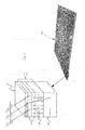
- FIG. 3 is a cross-sectional view illustrating a first embodiment of a micro-pixel included in a vertical silicon photomultiplier according to an exemplary embodiment of the present invention.
- the first embodiment of the vertical silicon photomultiplier 100 is configured in such a way that: a plurality of micro-pixels 600 is operated in the Geiger mode; a trench electrode 500 is placed around the micro-pixels 600 ; and a substrate 200 receives the micro-pixels 600 and the trench electrode 500 and has a portion, exposed to an external environment, for allowing the micro-pixels 600 and the trench electrode 500 to be connected to the external environment.
- a reverse bias voltage is applied between the trench electrode 500 and the micro-pixels 600 , horizontal electric fields are generated therebetween. If light is incident on the partially exposed substrate 200 , electron-hole pairs are generated by the electric fields between the micro-pixels 600 and the trench electrode 500 .
- the generation of electron-hole pairs causes the avalanche breakdown. Only if ultraviolet light 30 is incident on a depth close to the surface, it can react to the electric fields generated between the micro-pixels 600 and the trench electrode 500 . Therefore, the vertical silicon photomultiplier 100 can be reacted with light of wavelengths, i.e., from the ultraviolet light 30 to the infrared light 20 , thereby increase the quantum efficiency.
- the micro-pixel 600 is includes a p-type conductive epitaxial layer 300 and a PN-junction layer 400 vertically formed in the p-type conductive epitaxial layer 300 .
- the vertical PN-junction layer 400 is placed in the p-type conductive epitaxial layer 300 reacting to incident light. Electric fields are generated in the p-type conductive epitaxial layer 300 .
- the PN-junction layer 400 is formed perpendicular to the trench electrode 500 . A reverse bias is applied to the trench electrode 500 and the PN-junction layer 400 to horizontally generate electric fields.
- ultraviolet light 30 does not reach up to the PN-junction layer 400 but is incident at a depth close to the surface, electron-hole pairs are generated by electric fields generated between the trench electrode 500 and the PN-junction layer 400 to produce an avalanche breakdown.
- infrared light 20 when incident at a relatively deep depth, it reacts to the electric fields in the PN-junction layer 400 . Therefore, the quantum efficiency is incased at wavelengths (for example 200 ⁇ 900 nm).
- the PN-junction layer 400 is configured to include a p-type conductive layer 420 and n+ type conductive layer 410 placed on the outer side of the p-type conductive layer 420 .
- the PN-junction layer 400 generates very strong electric fields between the p-type conductive layer 420 and the n+ type conductive layer 410 , including the p-type conductive layer 420 and the n+ type conductive layer 410 , thereby a thin depletion region. When the depletion region is biased by the operation voltage, Geiger mode breakdown may occur.
- the PN-junction layer 400 is implemented in such a way that the n+ type conductive layer 410 is thicker by 2 ⁇ m than the p-type conductive layer 420 . This is to reduce noise in the sensor.
- FIG. 4 is a cross-sectional view illustrating a second embodiment of a micro-pixel included in a vertical silicon photomultiplier according to an exemplary embodiment of the present invention.
- FIG. 5 is a cross-sectional view illustrating a third embodiment of a micro-pixel included in a vertical silicon photomultiplier according to the present invention.
- the PN-junction layer may be implemented to be one of a rectangular V-letter shape 400 , bar shape 400 ′, and U-letter shape 400 ′′.
- the PN-junction layer is vertically formed in the V-letter shape 400 , the rectangular bar shape 400 ′ and U-letter shape 400 ′′, in the epitaxial layer 300 of the micro-pixel 600 , electric fields can be generated between the PN-junction layer 400 and the trench electrode 500 . If the PN-junction layer 400 is formed in the V-letter shape 400 and U-letter shape 400 ′′ in the epitaxial layer 300 of the micro-pixel 600 , although the visible light 10 , infrared light 20 and ultraviolet light 30 are transmitted to the conductive layer with different depths, they can reach the PN-junction layer 400 . Therefore, the quantum efficiency is increased. In order to form the PN-junction layer, the trench is vertically etched as being in the rectangular bar shape, U-letter shape, or V-letter shape, and then the PN-junction layer is formed on the trench sides.
- the PN-junction layer may be 10 ⁇ m high.
- the PN-junction layer can absorb visible light 10 , ultraviolet light 30 , and infrared light 20 .
- the infrared light 20 is transmitted to a relatively deep depth in the silicon, it can react to electric fields of the PN-junction layer formed in 10 ⁇ m deep.
- the trench electrode 500 can be formed by depositing metal. After a trench is formed around the vertical PN-junction layer, metal is deposited into the trench, thereby forming the trench electrode 500 . For example, a trench is formed around the vertical PN-junction layer 10 ⁇ m thick and metal is deposited in the trench. Through this process, a trench electrode is formed. When a reverse bias is applied to between the trench electrode 500 and the vertical PN-junction layer, electric fields are horizontally generated. Therefore, incident light transmitted into the silicon can react to the horizontally generated electric fields, irrespective of the transmission depth.
- FIG. 6 is a cross-sectional view illustrating a first embodiment of an arrangement of a trench electrode included in a vertical silicon photomultiplier according to an exemplary embodiment of the present invention.
- FIG. 7 is a cross-sectional view illustrating a second embodiment of an arrangement of a trench electrode included in a vertical silicon photomultiplier according to the present invention.
- FIG. 8 is a cross-sectional view illustrating a third embodiment of an arrangement of a trench electrode included in a vertical silicon photomultiplier according to the present invention.
- the trench electrode 500 may be arrayed around the micro-pixel 600 in one of a square surrounding strip, a square edge, and a hexagonal edge.
- the trench electrode 500 is arrayed around the micro-pixel 600 including the PN-junction layer.
- a reverse bias is applied between the trench electrode 500 and the PN-junction layer 400 is perpendicular to the trench electrode 500 , electric fields are horizontally generated therebetween.
- the trench electrode 500 can be formed in such a way that a trench is formed in a square shape around the micro-pixel 600 and then metal is deposited in the trench.
- the trench electrode 500 can be formed in such a way that a trench is formed in only the edge of the square around the micro-pixel 600 and then metal is deposited in the trench. As shown in FIG.
- the trench electrode 500 can be formed in such a way that a trench is formed in only the edge of the hexagon around the micro-pixel 600 and then metal is deposited in the trench. According to the shapes of the trench electrode 500 arrayed around the micro-pixel 600 , the voltage can be controlled and the intensity or the flux shape of electric fields, generated between the PN-junction layer and the trench electrode, can also be controlled.
- the trench electrode 500 may be 10 ⁇ 13 ⁇ m high.
- the vertical PN-junction layer 400 of a depth of 10 ⁇ m is formed in the epitaxial layer reacting to incident light.
- the trench electrode 500 of a depth of 10 ⁇ 13 ⁇ m is formed around the PN-junction layer.
- a reverse bias is applied to the trench electrode and the PN-junction layer, electric fields are generated. If the trench electrode 500 is approximately 10 ⁇ m the same as the PN-junction layer 400 or 13 ⁇ m higher than the PN-junction layer 400 , the reverse bias, applied to between the PN-junction layer 400 and the trench electrode 500 , may generate uniform horizontal electric fields therebetween.
- the vertical silicon photomultiplier according to the present invention includes a trench electrode and a PN-junction layer perpendicular to the trench electrode forms and can maximize the quantum efficiency at optical wavelengths, 200 ⁇ 900 nm in such a way that: it generates electric fields horizontal thereto, by applying a reverse bias voltage to between the trench electrode and the PN-junction layer, so that, although ultraviolet light does not reach the PN-junction layer but is incident on the surface, electron-hole pairs can be produced by the horizontally generated electric fields although and an avalanche breakdown can be thus generated; and it allows ultraviolet light, capable of being transmitted to a relatively deep depth, to react with the PN-junction layer.
Landscapes
- Engineering & Computer Science (AREA)
- Health & Medical Sciences (AREA)
- High Energy & Nuclear Physics (AREA)
- Physics & Mathematics (AREA)
- Spectroscopy & Molecular Physics (AREA)
- Molecular Biology (AREA)
- General Physics & Mathematics (AREA)
- Life Sciences & Earth Sciences (AREA)
- Chemical & Material Sciences (AREA)
- Environmental & Geological Engineering (AREA)
- Chemical Kinetics & Catalysis (AREA)
- Microelectronics & Electronic Packaging (AREA)
- Oil, Petroleum & Natural Gas (AREA)
- General Chemical & Material Sciences (AREA)
- Analytical Chemistry (AREA)
- Biomedical Technology (AREA)
- Light Receiving Elements (AREA)
Abstract
Description
-
- 10: visible light
- 20: infrared light
- 30: ultraviolet light
- 100: silicon photomultiplier
- 110: micro-pixel
- 120: PN-junction layer
- 130: epitaxial layer
- 140: substrate
- 200: substrate
- 300: epitaxial layer
- 400: PN-junction layer
- 410: n+-type conductive layer
- 420: p-type conductive layer
- 500: trench electrode
- 600: micro-pixel
Claims (11)
Applications Claiming Priority (2)
| Application Number | Priority Date | Filing Date | Title |
|---|---|---|---|
| KR1020100008215A KR101098165B1 (en) | 2010-01-29 | 2010-01-29 | Vertical silicon photomultipler with superior quantum efficiency at optical wavelengths |
| KR10-2010-0008215 | 2010-01-29 |
Publications (2)
| Publication Number | Publication Date |
|---|---|
| US20120025340A1 US20120025340A1 (en) | 2012-02-02 |
| US8421177B2 true US8421177B2 (en) | 2013-04-16 |
Family
ID=44063405
Family Applications (1)
| Application Number | Title | Priority Date | Filing Date |
|---|---|---|---|
| US13/014,961 Expired - Fee Related US8421177B2 (en) | 2010-01-29 | 2011-01-27 | Vertical silicon photomultiplier with superior quantum efficiency at optical wavelengths |
Country Status (4)
| Country | Link |
|---|---|
| US (1) | US8421177B2 (en) |
| EP (1) | EP2355155B1 (en) |
| JP (1) | JP5385315B2 (en) |
| KR (1) | KR101098165B1 (en) |
Families Citing this family (11)
| Publication number | Priority date | Publication date | Assignee | Title |
|---|---|---|---|---|
| SG193092A1 (en) | 2012-02-06 | 2013-09-30 | Agency Science Tech & Res | Semiconductor photomultiplier device |
| EP2747154B1 (en) | 2012-12-21 | 2020-04-01 | ams AG | Lateral single-photon avalanche diode and method of producing a lateral single-photon avalanche diode |
| EP2779255B1 (en) | 2013-03-15 | 2023-08-23 | ams AG | Lateral single-photon avalanche diode and their manufacturing method |
| US9274202B2 (en) | 2013-06-20 | 2016-03-01 | Analog Devices, Inc. | Optical time-of-flight system |
| US9435641B2 (en) * | 2013-06-20 | 2016-09-06 | Analog Devices, Inc. | Optical angle measurement |
| KR102728850B1 (en) | 2015-12-03 | 2024-11-13 | 소니 세미컨덕터 솔루션즈 가부시키가이샤 | Solid-state imaging element and imaging device |
| GB2576491A (en) * | 2018-07-17 | 2020-02-26 | Cambridge Entpr Ltd | A photodetector |
| JP7273545B2 (en) | 2019-03-07 | 2023-05-15 | 株式会社東芝 | Photodetector and distance measuring device |
| CN111710749B (en) * | 2020-04-23 | 2022-09-09 | 中国科学院上海技术物理研究所 | Splicing structure and realization method of long line detector based on secondary splicing of multiple substrates |
| GB2597109B (en) * | 2020-07-16 | 2023-05-10 | Plessey Semiconductors Ltd | Strain relaxation layer |
| JP2024127279A (en) * | 2023-03-09 | 2024-09-20 | ソニーセミコンダクタソリューションズ株式会社 | Photodetector |
Citations (1)
| Publication number | Priority date | Publication date | Assignee | Title |
|---|---|---|---|---|
| US20100148040A1 (en) * | 2008-12-17 | 2010-06-17 | Stmicroelectronics S.R.L. | Geiger-mode photodiode with integrated and adjustable quenching resistor, photodiode array, and manufacturing method thereof |
Family Cites Families (5)
| Publication number | Priority date | Publication date | Assignee | Title |
|---|---|---|---|---|
| JPH05226686A (en) * | 1992-02-17 | 1993-09-03 | Ricoh Co Ltd | Photodetector |
| US6541836B2 (en) * | 2001-02-21 | 2003-04-01 | Photon Imaging, Inc. | Semiconductor radiation detector with internal gain |
| US7714292B2 (en) * | 2006-02-01 | 2010-05-11 | Koninklijke Philips Electronics N.V. | Geiger mode avalanche photodiode |
| US8188563B2 (en) * | 2006-07-21 | 2012-05-29 | The Regents Of The University Of California | Shallow-trench-isolation (STI)-bounded single-photon CMOS photodetector |
| JP2008103614A (en) * | 2006-10-20 | 2008-05-01 | Mitsui Eng & Shipbuild Co Ltd | Photoelectric conversion device |
-
2010
- 2010-01-29 KR KR1020100008215A patent/KR101098165B1/en not_active Expired - Fee Related
-
2011
- 2011-01-27 EP EP11152327.0A patent/EP2355155B1/en not_active Not-in-force
- 2011-01-27 US US13/014,961 patent/US8421177B2/en not_active Expired - Fee Related
- 2011-01-28 JP JP2011015884A patent/JP5385315B2/en not_active Expired - Fee Related
Patent Citations (1)
| Publication number | Priority date | Publication date | Assignee | Title |
|---|---|---|---|---|
| US20100148040A1 (en) * | 2008-12-17 | 2010-06-17 | Stmicroelectronics S.R.L. | Geiger-mode photodiode with integrated and adjustable quenching resistor, photodiode array, and manufacturing method thereof |
Also Published As
| Publication number | Publication date |
|---|---|
| KR20110088633A (en) | 2011-08-04 |
| JP5385315B2 (en) | 2014-01-08 |
| EP2355155A2 (en) | 2011-08-10 |
| KR101098165B1 (en) | 2011-12-22 |
| EP2355155B1 (en) | 2015-08-05 |
| JP2011159972A (en) | 2011-08-18 |
| US20120025340A1 (en) | 2012-02-02 |
| EP2355155A3 (en) | 2013-04-10 |
Similar Documents
| Publication | Publication Date | Title |
|---|---|---|
| US8421177B2 (en) | Vertical silicon photomultiplier with superior quantum efficiency at optical wavelengths | |
| JP5791461B2 (en) | Photodetector | |
| JP5832852B2 (en) | Photodetector | |
| JP5926921B2 (en) | Photodetector | |
| JP6282368B2 (en) | Photodetector | |
| JP6663167B2 (en) | Photodetector | |
| JP5927334B2 (en) | Photodetector | |
| JP5911629B2 (en) | Photodetector | |
| JP2016197730A (en) | Semiconductor photo detector | |
| JP6318190B2 (en) | Photodetector | |
| CN111223956B (en) | A cascade avalanche multiplication photodiode | |
| CN211208467U (en) | Cascaded Avalanche Multiplier Photodiodes | |
| CN113574680B (en) | Avalanche photodetector (variation) and manufacturing method (variation) | |
| JP6186038B2 (en) | Semiconductor photo detector | |
| JP5989872B2 (en) | Photodetector connection structure | |
| KR101108716B1 (en) | Vertical Silicon Photomultiplier with Improved Quantum Efficiency Over All Wavelengths | |
| JP6116728B2 (en) | Semiconductor photo detector | |
| JP6244403B2 (en) | Semiconductor photo detector | |
| JP2016184753A (en) | Semiconductor photo detector |
Legal Events
| Date | Code | Title | Description |
|---|---|---|---|
| AS | Assignment |
Owner name: SENSE TECHNOLOGY, KOREA, REPUBLIC OF Free format text: ASSIGNMENT OF ASSIGNORS INTEREST;ASSIGNOR:PARK, IL HUNG;REEL/FRAME:025706/0483 Effective date: 20110126 Owner name: EWHA UNIVERSITY-INDUSTRY COLLABORATION FOUNDATION, Free format text: ASSIGNMENT OF ASSIGNORS INTEREST;ASSIGNOR:PARK, IL HUNG;REEL/FRAME:025706/0483 Effective date: 20110126 |
|
| STCF | Information on status: patent grant |
Free format text: PATENTED CASE |
|
| AS | Assignment |
Owner name: SATBYUL CO., LTD., KOREA, REPUBLIC OF Free format text: ASSIGNMENT OF ASSIGNORS INTEREST;ASSIGNORS:EWHA UNIVERSITY-INDUSTRY COLLABORATION FOUNDATION;SENSE TECHNOLOGY;SIGNING DATES FROM 20151102 TO 20151105;REEL/FRAME:037129/0483 |
|
| FPAY | Fee payment |
Year of fee payment: 4 |
|
| FEPP | Fee payment procedure |
Free format text: MAINTENANCE FEE REMINDER MAILED (ORIGINAL EVENT CODE: REM.); ENTITY STATUS OF PATENT OWNER: SMALL ENTITY |
|
| LAPS | Lapse for failure to pay maintenance fees |
Free format text: PATENT EXPIRED FOR FAILURE TO PAY MAINTENANCE FEES (ORIGINAL EVENT CODE: EXP.); ENTITY STATUS OF PATENT OWNER: SMALL ENTITY |
|
| STCH | Information on status: patent discontinuation |
Free format text: PATENT EXPIRED DUE TO NONPAYMENT OF MAINTENANCE FEES UNDER 37 CFR 1.362 |
|
| FP | Lapsed due to failure to pay maintenance fee |
Effective date: 20210416 |