US8416284B2 - Stereoscopic image capturing apparatus and stereoscopic image capturing system - Google Patents
Stereoscopic image capturing apparatus and stereoscopic image capturing system Download PDFInfo
- Publication number
- US8416284B2 US8416284B2 US12/461,179 US46117909A US8416284B2 US 8416284 B2 US8416284 B2 US 8416284B2 US 46117909 A US46117909 A US 46117909A US 8416284 B2 US8416284 B2 US 8416284B2
- Authority
- US
- United States
- Prior art keywords
- image
- unit
- parallax vector
- parallax
- lens array
- Prior art date
- Legal status (The legal status is an assumption and is not a legal conclusion. Google has not performed a legal analysis and makes no representation as to the accuracy of the status listed.)
- Expired - Fee Related, expires
Links
Images


Classifications
-
- G—PHYSICS
- G02—OPTICS
- G02B—OPTICAL ELEMENTS, SYSTEMS OR APPARATUS
- G02B30/00—Optical systems or apparatus for producing three-dimensional [3D] effects, e.g. stereoscopic images
- G02B30/20—Optical systems or apparatus for producing three-dimensional [3D] effects, e.g. stereoscopic images by providing first and second parallax images to an observer's left and right eyes
- G02B30/26—Optical systems or apparatus for producing three-dimensional [3D] effects, e.g. stereoscopic images by providing first and second parallax images to an observer's left and right eyes of the autostereoscopic type
- G02B30/27—Optical systems or apparatus for producing three-dimensional [3D] effects, e.g. stereoscopic images by providing first and second parallax images to an observer's left and right eyes of the autostereoscopic type involving lenticular arrays
-
- H—ELECTRICITY
- H04—ELECTRIC COMMUNICATION TECHNIQUE
- H04N—PICTORIAL COMMUNICATION, e.g. TELEVISION
- H04N13/00—Stereoscopic video systems; Multi-view video systems; Details thereof
- H04N13/10—Processing, recording or transmission of stereoscopic or multi-view image signals
- H04N13/106—Processing image signals
- H04N13/139—Format conversion, e.g. of frame-rate or size
-
- H—ELECTRICITY
- H04—ELECTRIC COMMUNICATION TECHNIQUE
- H04N—PICTORIAL COMMUNICATION, e.g. TELEVISION
- H04N13/00—Stereoscopic video systems; Multi-view video systems; Details thereof
- H04N13/20—Image signal generators
- H04N13/204—Image signal generators using stereoscopic image cameras
- H04N13/239—Image signal generators using stereoscopic image cameras using two two-dimensional [2D] image sensors having a relative position equal to or related to the interocular distance
-
- H—ELECTRICITY
- H04—ELECTRIC COMMUNICATION TECHNIQUE
- H04N—PICTORIAL COMMUNICATION, e.g. TELEVISION
- H04N13/00—Stereoscopic video systems; Multi-view video systems; Details thereof
- H04N13/30—Image reproducers
- H04N13/302—Image reproducers for viewing without the aid of special glasses, i.e. using autostereoscopic displays
- H04N13/31—Image reproducers for viewing without the aid of special glasses, i.e. using autostereoscopic displays using parallax barriers
Definitions
- the present invention relates to a stereoscopic image capturing apparatus and system for obtaining stereoscopic image information to be displayed on a display.
- a large number of cameras, movable cameras, or laser scans are used to acquire stereoscopic image information of an object having a depth. If a large number of cameras are used, then the picture quality is degraded by individual differences and installation precisions of respective cameras. In the movable cameras, dispersion among systems which drive the movable cameras poses a problem.
- JP-A 10-224820 a stereoscopic image capturing apparatus using stereo cameras.
- multi-parallax image information is generated by performing interpolation.
- JP-A 2007-286521 a stereoscopic image capturing apparatus using a multi-camera array is proposed (JP-A 2007-286521).
- JP-A 2007-286521 a stereoscopic image capturing apparatus using a multi-camera array.
- it is not necessary to perform interpolation because a large number of cameras are used. Even if interpolation is performed, there is little degradation in the interpolated image because multi-parallax information obtained from multiple cameras can be utilized.
- a stereoscopic image capturing apparatus using an IP (Integral Photography) system which uses a microlens array is known (JP-A 2006-304230).
- IP Integral Photography
- JP-A 2006-304230 a stereoscopic image capturing apparatus using an IP (Integral Photography) system which uses a microlens array.
- the present invention has been made in view of these circumstances, and an object thereof is to provide a stereoscopic image capturing apparatus and a stereoscopic image capturing system capable of capturing a stereoscopic image from which a multi-parallax image with a reduced data quantity and a high picture quality can be synthesized.
- a stereoscopic image capturing apparatus includes a first image acquisition unit including a first image formation lens unit which forms a image of an object, and a first image sensor having a plurality of capturing pixels on a surface thereof to receive the image formed by the first image acquisition unit and convert the image to an electric signal, and a second image acquisition unit including a second image formation lens unit which forms a image of the object, a first lens array unit having a plurality of lenses arranged in an array form to receive the image formed by the second image formation lens, and a second image sensor having a plurality of capturing pixels on a surface thereof to receive the formed image through the first lens array unit and convert the image to an electric signal, the second image acquisition unit being disposed at a distance in a horizontal direction from the first image acquisition unit when viewed from the object.
- a stereoscopic image capturing system includes a stereoscopic image capturing apparatus according to the first aspect, and a parallax vector generation processing unit which performs parallax vector generation processing on the basis of images of the object acquired by the first image acquisition unit and the second image acquisition unit, the parallax vector generation processing unit including a parallax vector extraction unit which extracts a parallax vector on the basis of the image acquired by the second image acquisition unit, an associated point search unit which searches for an associated point of an image acquired by the first image acquisition unit and a parallax vector extracted by the parallax vector extraction unit, and a parallax vector interpolation unit which interpolates a resolution of the parallax vector by using the associated point searched for by the associated point search unit and the image acquired by the first image acquisition unit.
- FIG. 1 is an oblique view showing a concrete example of a stereoscopic image display apparatus
- FIG. 2 is a diagram showing relations between a stereoscopic image display apparatus and a stereoscopic image
- FIG. 3 is an oblique view showing another concrete example of a stereoscopic image display apparatus
- FIG. 4 is a front view of a slit array plate
- FIG. 5 is a plan view showing a stereoscopic image capturing apparatus according to a first embodiment
- FIG. 6 is a front view of the stereoscopic image capturing apparatus according to the first embodiment
- FIG. 7 is a plan view showing an optical system in a lens array camera
- FIG. 8 is a plan view showing an optical system in a main camera
- FIG. 9 is a plan view showing a stereoscopic image capturing apparatus according to a second embodiment.
- FIG. 10 is a front view of the stereoscopic image capturing apparatus according to the second embodiment.
- FIG. 11 is a front view of a stereoscopic image capturing apparatus according to a third embodiment
- FIG. 12 is a front view of a stereoscopic image capturing apparatus according to a fourth embodiment
- FIG. 13 is a front view of a stereoscopic image capturing apparatus according to a fifth embodiment
- FIG. 14 is a diagram showing relations between a lens pitch of a lens array and an image sensor
- FIG. 15 is a diagram showing a convergence arrangement of cameras
- FIG. 16 is a diagram for explaining a shift arrangement of image sensors
- FIG. 17 is a block diagram showing a stereoscopic image capturing system according to a sixth embodiment.
- FIG. 18 is a diagram for explaining relations between light rays and parallax angles
- FIG. 19 is a diagram showing relations between a light ray space and acquired images
- FIG. 20 is a diagram showing a light ray space obtained when the lens pitch of the lens array is an integer times as large as the pixel pitch of the image sensor;
- FIG. 21 is a diagram for explaining relations between a coordinate system and cameras
- FIG. 22 is a diagram showing a simple light ray space
- FIG. 23 is a block diagram showing a stereoscopic image capturing system according to a modification of the sixth embodiment
- FIG. 24 is a flow chart showing a parallax vector extraction procedure
- FIG. 25 is a diagram showing parallax vector extraction processing on the light ray space
- FIGS. 26( a ) and 26 ( b ) are diagrams for explaining a parallax vector in the real space and the light ray space;
- FIG. 27 is a diagram for explaining pixel interpolation processing on the light ray space in the case where there is a corresponding point
- FIG. 28 is a diagram for explaining pixel exception processing on the light ray space in the case where there isn't a corresponding point;
- FIGS. 29A to 29C are diagrams for explaining other pixel exception processing on the light ray space in the case where there isn't a corresponding point;
- FIG. 30 is a flow chart for explaining a procedure of multiple visual point image generation processing
- FIG. 31 is a diagram for explaining the multiple visual point image generation processing on the light ray space
- FIG. 32 is a flow chart showing a processing procedure of data transmission.
- FIG. 33 is a flow chart showing a processing procedure of data retention.
- a stereoscopic image capturing apparatus or a stereoscopic image capturing system is an apparatus or a system for recording a stereoscopic image required for reproduction when reproducing the stereoscopic image by using a stereoscopic image display apparatus.
- the stereoscopic image display apparatus Prior to description of the stereoscopic image capturing apparatus or the stereoscopic image capturing system according to an embodiment of the present invention, therefore, the stereoscopic image display apparatus will now be described.
- a stereoscopic image display apparatus which displays a stereoscopic image will be described with reference to FIGS. 1 to 4 .
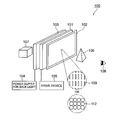
- a stereoscopic image display apparatus 100 includes a LCD 101 serving as a plane display device having a display face formed of pixels each of which includes subpixels of three primary colors R, G and B and which are arranged in a matrix form, an optical plate 102 provided in front of the display face of the LCD 101 to control light rays from pixels of the LCD 101 , and a back light 103 provided on the opposite side of the LCD 101 from the optical plate 102 (on the back face side of the LCD 101 ) and driven by a back light power supply 104 .
- a LCD 101 serving as a plane display device having a display face formed of pixels each of which includes subpixels of three primary colors R, G and B and which are arranged in a matrix form
- an optical plate 102 provided in front of the display face of the LCD 101 to control light rays from pixels of the LCD 101
- a back light 103 provided on the opposite side of the LCD 101 from the optical plate 102 (on the back face side of the LCD 101 ) and driven by a back light power supply
- the LCD 101 is electrically driven by a drive device 105 , and parallax information is displayed on each column of the display face. Light emitted from the back light 103 illuminates the display face of the LCD 101 .
- the optical plate 102 is disposed in a location between the display face of the LCD 101 and a viewer 108 .
- the optical plate 102 can be formed of, for example, a pinhole array plate having pinholes arranged in an array form.
- a three-dimensional real image 106 is reproduced by a light ray group emitted from pinholes 109 of the pinhole array plate 102 , and recognized by the viewer 108 .
- the known microlens array having microlenses 112 arranged in an array form instead of the pinholes 109 may be used.
- FIG. 2 is a diagram obtained by viewing location relations between the stereoscopic image display apparatus 100 shown in FIG. 1 and the three-dimensional image 106 from the above.
- the LCD 101 disposed behind the pinhole array plate 102 when viewed from the viewer 108 displays a parallax image group which differs in how it looks delicately according to the angle, i.e., a multiple visual point image (for example, an image formed of information stored in pixels of #1 to #7).
- a multiple visual point image for example, an image formed of information stored in pixels of #1 to #7.
- Light emitted from the multiple visual point image is passed through the pinholes 109 to produce a large number of parallax image light ray groups. They are condensed to reproduce the three-dimensional real image 106 (stereoscopic image).
- each subpixel displays information of luminance and color obtained at a point where a straight line passing through the subpixel and the center of the pinhole 109 intersects a stereoscopic image on the display space.
- a straight line drawn from the same subpixel through the same pinhole 109 “intersects the stereoscopic image 106 ” at a plurality of points.
- a point which is nearest the viewer 108 is regarded as a display point.
- a point P 1 located nearer the viewer 108 than a point P 2 is regarded as the display point.
- the stereoscopic image display apparatus 100 may have a configuration in which a slit array plate 110 having a plurality of slits 111 arranged in parallel as shown in FIG. 3 is disposed instead of the pinhole array plate serving as the optical plate 102 as shown in FIG. 1 .
- FIG. 4 is a schematic diagram obtained by viewing the slit array plate 110 from the front. As shown in FIG. 4 , the slits 111 are provided so as to be nearly parallel to the longitudinal direction (vertical direction) of the arrangement of the subpixels R, G and B. In the configuration in the case where the slit array plate 110 is used, therefore, the parallax in the vertical direction is not considered.
- the slit array plate 110 is easier in fabrication than the pinhole array plate, and the slit array plate 110 can reproduce a natural and highly definite stereoscopic image having no color separation in the same way as the pinhole array plate 102 .
- a lenticular sheet 113 may also be used instead of the slit array plate 110 .
- FIG. 1 A stereoscopic image capturing apparatus according to a first embodiment of the present invention is shown in FIG. 1 .
- FIG. 5 is a plan view of the stereoscopic image capturing apparatus according to the present embodiment.
- the stereoscopic image capturing apparatus according to the present embodiment includes a lens array camera 10 and a camera 20 . These cameras 10 and 20 are arranged so as to line up in the horizontal direction when viewed from an object 200 and so as to be common in an imaging area.
- the lens array camera 10 includes an image sensor 12 having photoelectric conversion elements, such as CCDs or CMOSs, (hereafter referred to as capturing pixels or simply pixels as well) capable of capturing a two-dimensional image arranged in a matrix form, a lens array 14 provided in the front of the image sensor 12 , and an optical system including an image formation lens 16 to focus light rays from an object to be captured on an image sensor 12 thorough the lens array 14 .
- the camera 20 includes an image sensor 22 having capturing pixels arranged in a matrix form and an optical system including an image formation lens 26 to focus light rays from an object to be captured on an image sensor 22 . And each of lenses included in the lens array 14 is formed so as to cover a plurality of capturing pixels.
- a first straight line which couples a center of the image sensor 12 to a center of the image formation lens 16 is nearly perpendicular to an object plane 200 a
- a second straight line which couples a center of the image sensor 22 to a center of the image formation lens 26 is nearly perpendicular to the object plane 200 a
- the first and second straight lines are disposed on the same plane in the horizontal direction when viewed from the object 200 .
- the object plane 200 a means a perpendicular to the object 200 which includes the object 200 .
- a configuration in which the lens array camera 10 and the camera 20 having no lens array (hereafter referred to as main camera as well) include an overlapping part in an imaging area and a common object is captured becomes a basic form.
- the lens array camera 10 can acquire images including a plurality of images from different directions (parallax images) at the same time. Since the lens array camera 10 and the camera 20 are disposed so as to line up in the horizontal direction and have a distance between when viewed from the object 200 , there is also a parallax between the lens array camera 10 and the camera 20 .
- a cylindrical lens array having a cylindrical shape is taken as an example. However, a microlens array can also be used.
- FIG. 6 is a front view obtained when the lens array camera 10 and the camera 20 are viewed from a direction of an arrow z (direction of the object 200 ) in FIG. 5 .
- the camera 10 using a cylindrical lens array can capture an image having a parallax in a direction which is nearly perpendicular to a ridgeline of a lens (a direction having lens power).
- the camera 20 is installed in the direction having a parallax. Such installation brings about an arrangement in which the parallax captured by the lens array camera 10 and the parallax of the camera 20 have the same vector.
- a base line 30 of the lens array camera 10 and the camera 20 i.e., a line 30 which couples a center of the lens array camera 10 to a center of the camera 20 is in a direction which is nearly perpendicular to a ridgeline 36 of a cylindrical lens 35 .
- the stereoscopic image capturing apparatus includes at least the lens array camera 10 and the camera 20 having no lens array.
- the stereoscopic image capturing apparatus according to the present embodiment captures a plurality of parallax images by using images of a low resolution with the lens array camera 10 and a high resolution image by using the camera 20 .
- the stereoscopic image capturing apparatus according to the present embodiment is configured so as to cause vectors of the parallax between the cameras 10 and 20 and the parallax of the lens array camera 10 to coincide with each other.
- the image captured by the stereoscopic image capturing apparatus includes a plurality of images having fine parallax intervals and one image having the same vector as the images and a large parallax interval.
- the image captured by the stereoscopic image capturing apparatus according to the present embodiment includes images having a fine resolution and the image having a coarse resolution.
- the images captured by the stereoscopic image capturing apparatus according to the present embodiment are information in which the parallax and resolution can be easily interpolated. Therefore, the stereoscopic image capturing apparatus according to the present embodiment can capture images which are capable of interpolating multi-parallax images which are small in data quantity and high in resolution.
- FIG. 7 shows the optical system in the lens array camera 10 according to the present embodiment.
- the lens array 14 is in an image formation relation to a virtual image lens array VLA which is considered to be in a location of the object 200 .
- An image captured at this time becomes an integral image observed through the virtual image lens array VLA by using the plane of the image formation lens 16 as the common imaging plane.
- the integral image is an image captured through the lens array or the like.
- a minute image called elemental image is captured by each of the lenses.
- the angle area of the parallax corresponds to the angle of view of the lens, and the number of parallaxes corresponds to the number of pixels of the elemental image. Furthermore, it is also possible to separate a multiple visual point image by reconstructing the integral image. Therefore, the resolution of the multiple visual point image reconstructed from the integral image which is captured by the present optical system corresponds to the lens pitch of the virtual image lens array VLA. And the parallax angle range ⁇ P which can be captured becomes an angle obtained by viewing an aperture d 2 of the image formation lens 16 from the lens center of the virtual image lens array VLA.
- the parallax angle range ⁇ P can be represented by Expression (4). Furthermore, the number of parallaxes N depends upon the number of image sensors assigned to each lens array.
- the angle pitch ⁇ Pi becomes of one parallax can be represented by Expression (5).
- ⁇ means that both sides thereof are nearly equal. It is meant that the left side can be approximated by the expression on the right side.
- Expression (4) and Expression (5) are approximation expressions at the center of the lens 16 , and they differ slightly depending upon the location. Since the integral image has the image formation lens as the common imaging plane, ⁇ P has a feature that it shifts toward the screen end unlike the ordinary integral image. This shift quantity corresponds to an angle shift of an image having a perspective.
- the perspective corresponds to an angle shift of an image according to perspective representation.
- the image according to the perspective representation can be compared to an image of a pinhole camera, and it is an image formed from light rays having different angles with the pinhole center used as the reference axis.
- the center of the pinhole corresponds to the image formation lens 16 .
- the lens array camera 10 can capture an integral image having a perspective.
- the angle of view ⁇ c1 of this image can be represented by Expression (6).
- ⁇ c1 2 ⁇ tan ⁇ 1 ( d 3/(2 ⁇ b )) (6)
- d 3 is a lens array width.
- a width d 1 of the elemental image in the integral image is designed according to Expression (7) on the basis of a pixel pitch P P and the number of parallaxes N.
- a lens pitch of the lens array 14 is designed on the basis of the pixel pitch P P and the number of parallaxes N. Details thereof will be described with reference to a third embodiment.
- a region where actual light enters depends upon the aperture width d 2 of the image formation lens 16 .
- the distance “a” from the lens array 14 for ensuring the width d 1 of the elemental image should be determined according to Expression (8). If the distance “a” deviates from the value represented by Expression (8), then crosstalk between elemental images or a dark line is caused.
- the distance “a” can be regulated by adjusting the width d 1 instead of the distance “a”.
- d 1 P P ⁇ N (7)
- a b ⁇ d 1 /d 2 (8)
- the focal length f LA of the lens array 14 can be determined according to Expression (3) by using the focal length f L1 of the image formation lens 16 in the lens array camera 10 and the distance “b”.
- FIG. 8 An optical system in the camera 20 is shown in FIG. 8 .
- d 4 denotes an aperture of the image formation lens 16
- d 5 denotes an image sensor effective area
- g denotes a distance between an imaging plane 22 a of the image sensor 22 and the image formation lens 26
- h denotes a distance between the image formation lens 26 and the object 200 .
- Relations among the angle of view ⁇ c2 , the distance g, the distance h, d 4 and d 5 are the same as those in the ordinary camera, and a similar design should be performed.
- the focal length f L2 of the image formation lens 26 and the distance g design is performed in the same way as the ordinary camera. This will be described in detail later.
- FIG. 9 is a plan view of the stereoscopic image capturing apparatus according to the present embodiment.
- FIG. 10 is a front view of the stereoscopic image capturing apparatus obtained when viewed from a direction of an arrow z (direction of the object) shown in FIG. 9 .
- the stereoscopic image capturing apparatus according to the present embodiment includes two lens array cameras 10 1 and 10 2 and a camera 20 .
- the present embodiment has a configuration obtained by providing one additional lens array camera in the first embodiment.
- the lens array cameras 10 1 and 10 2 are disposed on the left and right sides of the camera 20 in the horizontal direction when viewed from the object.
- a base line 30 1 between the lens array camera 10 1 and the camera 20 and a base line 30 2 between the lens array camera 10 2 and the camera 20 are arranged so as to be disposed nearly on the same straight line. At this time, therefore, arrangement is performed so as to cause ridgelines of cylindrical lenses included in each of the lens arrays 14 1 and 14 2 respectively in the lens array cameras 10 1 and 10 2 to be nearly perpendicular to the base lines between the cameras. It is also possible to use at least two lens array cameras in this way. In this case, an overlap portion of imaging areas becomes a utilization area. Therefore, it is also possible to capture the same area of the object while utilizing the whole of the image sensor face of the image sensors 12 1 and 12 2 and the image sensor 22 , i.e., use pixels effectively by performing convergence arrangement of cameras or shift arrangement of the cameras.
- the images captured by the stereoscopic image capturing apparatus according to the present embodiment are information in which the parallax and resolution can be easily interpolated in the same way as the first embodiment. Therefore, the stereoscopic image capturing apparatus according to the present embodiment can capture images which are capable of interpolating multi-parallax images which are small in data quantity and high in resolution.
- FIG. 11 is a front view of the stereoscopic image capturing apparatus according to the present embodiment obtained when viewed from the object.
- the stereoscopic image capturing apparatus according to this embodiment has a configuration obtained from that of the stereoscopic image capturing apparatus according to the second embodiment by arranging the lens array cameras 10 1 and 10 2 and the camera 20 so as to cause a base line 30 1 between the lens array camera 10 1 and the camera 20 to be nearly perpendicular to a base line 30 2 between the lens array camera 10 2 and the camera 20 .
- the lens array camera 10 1 when viewed from the object, the lens array camera 10 1 is disposed in the horizontal direction of the camera 20 and the lens array camera 10 2 is disposed in the vertical direction of the camera 20 .
- Ridgelines of cylindrical lenses in the lens array camera 10 1 disposed in the horizontal direction extend in the vertical direction when viewed from the object, and are nearly perpendicular to the base line 30 1 between the lens array camera 10 1 and the camera 20 .
- ridgelines of cylindrical lenses in the lens array camera 10 2 disposed in the vertical direction extend in the horizontal direction when viewed from the object, and are nearly perpendicular to the base line 30 2 between the lens array camera 10 2 and the camera 20 .
- the lens array cameras 10 1 and 10 2 can be disposed at different angles such as in the horizontal direction or the vertical direction with the camera 20 disposed in common.
- a base line 30 1 between the lens array camera 10 1 and the camera 20 and a base line 30 2 between the lens array camera 10 2 and the camera 20 are arranged so as to be nearly perpendicular to each other. This is because the parallax vector is in a direction perpendicular to the lens array, and it becomes easy to interpolate the parallax and resolution by aligning parallax vectors between cameras. If such an arrangement is performed, then the parallax vector is obtained as its horizontal component and its vertical component, and consequently a three-dimensional parallax vector can be found.
- pixels can be used effectively by performing convergence arrangement of cameras or shift arrangement of the cameras.
- the images captured by the stereoscopic image capturing apparatus according to the present embodiment are information in which the parallax and resolution can be easily interpolated in the same way as the first embodiment. Therefore, the stereoscopic image capturing apparatus according to the present embodiment can capture images which are capable of interpolating multi-parallax images which are small in data quantity and high in resolution.
- FIG. 12 is a front view of the stereoscopic image capturing apparatus according to the present embodiment obtained when viewed from the object.
- the stereoscopic image capturing apparatus according to the present embodiment has a configuration obtained by arranging one lens array camera 10 1 having a microlens array as its lens array, and two cameras 20 1 and 20 2 which do not have a lens array so as to cause a base line 30 1 between the lens array camera 10 1 and the camera 20 1 to be nearly perpendicular to a base line 31 2 between the lens array camera 10 1 and the camera 20 2 .
- the camera 20 1 is disposed in a horizontal direction to the lens array camera 10 1 and the camera 20 2 is disposed in a vertical direction to the lens array camera 10 1 viewed from the object.
- the lens array camera 10 1 having a microlens array can acquire a three-dimensional parallax including horizontal and vertical parallaxes.
- the resolution of the elemental image using the microlens is degraded to one severalth of the parallax in both the horizontal and vertical directions.
- two cameras 20 1 and 20 2 are disposed so as to bring about a coordinate system in which parallax vectors of image data are perpendicular to each other, and the corresponding image data are interpolated. In this way, a plurality of cameras 20 1 and 20 2 having no lens arrays can be disposed.
- pixels can also be used effectively by performing convergence arrangement of cameras or shift arrangement of the cameras.
- FIG. 13 is a front view of the stereoscopic image capturing apparatus according to the present embodiment obtained when viewed from the object.
- the stereoscopic image capturing apparatus according to the present embodiment has a configuration obtained from the stereoscopic image capturing apparatus according to the fourth embodiment shown in FIG. 12 by providing one additional lens array camera 10 2 having a microlens array as a lens array and causing a base line 31 3 between the lens array camera 10 2 and the camera 20 1 and a base line 31 4 between the lens array camera 10 2 and the camera 20 2 are arranged so as to be perpendicular to each other.
- the images captured by the stereoscopic image capturing apparatus according to the present embodiment are information in which the parallax and resolution can be easily interpolated in the same way as the first embodiment. Therefore, the stereoscopic image capturing apparatus according to the present embodiment can capture images which are capable of interpolating multi-parallax images which are small in data quantity and high in resolution.
- both the microlens array and the cylindrical lens array are considerable.
- the case where the cylindrical lens array is used will be described in more detail.
- the cylindrical lens array includes cylindrical lenses each taking the shape of a cylindrical lens arranged in an array form.
- the cylindrical lens array has its lens power only in a direction perpendicular to ridgelines of the cylindrical lenses. Therefore, a lens array camera using a cylindrical lens array can capture an image having a parallax only in a direction having the lens power.
- a lens 35 is disposed so as to have a ridgeline 36 in the vertical direction viewed from the object, the camera 20 is disposed in a location deviated from the lens array camera 10 in the horizontal direction.
- the lens array camera 10 has a parallax in the horizontal direction, and it coincides with the parallax between the cameras.
- the horizontal resolution lowers to one severalth of the parallax assigned to the horizontal direction. As compared with a microlens array in which the resolution degradation occurs in the horizontal and vertical directions, the resolution degrades only in the horizontal direction. Therefore, the efficiency is high in extracting the parallax vector.
- FIG. 14 is a diagram for explaining the relations between the lens pitch of the lens array 14 and the pixels of the image sensor 12 .
- the center of an elemental image is on a line extended from a line which couples the center of the image formation lens 16 and a center of each of lenses included in the lens array 14 .
- the elemental image width d 1 (called elemental image pitch as well) corresponds to intervals between straight lines passing through centers of the elemental images on the image sensor plane 12 a .
- angle data of each lens in the lens array 14 becomes angle data which differs in angle according to the image location unlike equal interval angle data obtained by one image sensor 12 .
- the elemental image pitch d 1 satisfies Expression (9), it assumes a value which is slightly larger than the value represented by Expression (7).
- the elemental image width d 1 does not become a discrete value of the pixel value.
- the shift quantity ⁇ ps is also quantized on the same scale. Therefore, the shift quantity of the capturing angle can be handled as a discrete value taking a pixel as the unit. This means that the angle of the plane of the virtual image lens array VLA is quantized discretely. It is facilitated to handle a coordinate system handling the angle.
- parallax data obtained from the lens array camera 10 which obtains different angle data according to the pixel location can be handled with angle data quantized at equal angle intervals which is obtained from the pixel interval in the image sensor. Even if Lp obtained by substituting Expression (11) or Expression (7) into Expression (9) cannot be reproduced strictly, it is possible to perform adjustment by quantization with a pixel taken as the unit.
- the optical system in the camera 20 becomes an optical system which forms an image from light at different angles with the lens center taken as the axis and records the image.
- the image can be said to be an image having a perspective.
- a retinal image viewed by the naked eyes is similar, and a natural image felt by human being can be captured.
- Association of the image of the camera 20 with pixels of the lens array camera 10 inclusive of the angle dimension is simplified by making the perspectives equal to each other.
- the focal length of the camera 20 should be made equal to that of the lens array camera 10 and the distance “b” shown in FIG. 7 should be made equal to a distance “g” shown in FIG. 8 .
- angles of view ⁇ c1 and ⁇ c2 between the cameras can be made equal to each other.
- FIG. 15 is a plan view showing an example of the convergence arrangement of the cameras.
- a part corresponding as an image becomes an overlap part of imaging areas. If the camera 20 and the lens array camera 10 face to the same direction as shown in FIG. 5 described in the first embodiment, then a part which does not overlap occurs in the imaging area and pixels in that part do not become effective.
- the effective area of pixels can be expanded.
- the object plane 200 a inclines to the image sensor plane. Because of the effect of the perspective in addition, distortion like a key stone occurs in a rectangle shape on the object plane 200 a . Since this distortion can also be corrected by a projection change, it is also possible to correct the distortion by image processing.
- the convergence arrangement is disadvantageous in processing time and cost, then distortion can be prevented from being generated by disposing the image sensors 12 and 22 in locations shifted from the image formation lenses 16 and 26 as shown in FIG. 16 .
- the distance between the center of the image sensor 12 and the center of the second image sensor 22 is greater than the distance between the center of the image formation lens 16 and the center of the image formation lens 26 .
- this shift arrangement is made possible by inclining a line coupling the center of the image sensor 12 and the center of the image formation lens 16 so as to shift an angle formed by the line and the object plane 200 a from 90 degrees by a shift quantity ⁇ s and inclining a line coupling the center of the image sensor 22 and the center of the image formation lens 26 so as to shift an angle formed by the line and the object plane 200 a from 90 degrees by the shift quantity ⁇ s .
- the key stone type distortion does not occur unlike the convergence arrangement, because the object plane 200 a does not differ between cameras.
- Expression (13) corresponds to the case where the cameras 10 and 20 are shifted by the same angle and the object 200 located in the center between the cameras is supposed. It is also possible to design shift quantities which differ from camera to camera in the camera arrangement. If the shift quantity is large, then there is a possibility that image distortion due to the image formation characteristics or the lens will be caused by extra-axis aberration or the like. Therefore, it is conceivable to design the image formation lenses supposing the shifted image planes.
- Embodiments of the stereoscopic image capturing system according to the present invention will now be described with reference to the drawings.
- the stereoscopic image capturing systems according to the ensuing embodiments are based on the assumption that the above-described stereoscopic image capturing apparatus is used.
- FIG. 17 is a block diagram showing a schematic configuration of the stereoscopic image capturing system according to the present embodiment.
- the stereoscopic image capturing system according to the present embodiment includes at least two image acquisition units 51 and 52 , a parallax vector generation processing unit 54 , a multiple visual point image generation unit 56 , and a stereoscopic image display data output unit 58 .
- the image acquisition unit 51 corresponds to a camera which does not have a lens array (for example, the camera 20 shown in FIG. 5 ), and the image acquisition unit 52 corresponds to a lens array camera (for example, the camera 10 shown in FIG. 5 ).
- the lens array camera 10 is low in resolution, but it can capture the parallax.
- the parallax vector generation processing unit 54 includes a parallax vector extraction unit 54 a , an associated point search unit 54 b , a parallax vector interpolation unit 54 c , and a parallax vector output unit 54 d .
- the parallax vector extraction unit 54 a extracts a parallax vector on the basis of image data acquired by the image acquisition unit 52 which is low in resolution but which has a parallax.
- the associated point search unit 54 b searches for and obtains a point associated with high resolution image data which is associated with the extracted parallax vector and acquired by the image acquisition unit 51 .
- the parallax vector interpolation unit 54 c interpolates resolution of the associated low resolution parallax vector by using high resolution image data at the obtained associated point.
- the parallax vector output unit 54 d outputs the parallax vector interpolated by the parallax vector interpolation unit 54 c . Data thus generated can be output as a parallax vector having a high resolution and a high precision.
- the multiple visual point image generation unit 56 generates a visual point image at an arbitrary angle, i.e., a multiple visual point image by using the parallax vector output from the parallax vector output unit 54 d .
- Stereoscopic image display data required for stereoscopic image display is generated by using the generated multiple visual point image and output from the stereoscopic image display data output unit 58 .
- Visual information containing depth information of the captured space can be presented by performing pixel conversion conformed to the stereoscopic image display apparatus and displaying the result.
- the stereoscopic image capturing system becomes an image system capable of interpolating high resolution multi-parallax images from images captured with a reduced quantity of data. It is also possible to perform high quality stereoscopic display by using the multi-parallax data.
- the parallax quantity of a camera having no lens array depends upon the relative location of the main camera with respect to a lens array camera paired with the main camera.
- An angle formed by an optical axis of the lens array camera and an optical axis of the main camera is a main angle difference between the cameras, and this becomes a relative parallax angle.
- the relative main parallax angle may be considered to be twice the shift angle ⁇ s represented by Expression (13). If an axis perpendicular to the image sensors 12 and 22 is defined as a reference axis, the main parallax angle becomes an angle formed by the reference axis and the optical axis.
- the main parallax angle can be given by the shift angle ⁇ s represented by Expression (13) (the sign is given by the coordinate system).
- an image of perspective projection with the principal point of the lens taken as the center can be captured.
- the angle of acquired light differs from pixel to pixel.
- the parallax angle of the captured pixel becomes an angle which couples a pixel location and the principal point of the lens.
- Calculation can be performed in the same way in the case where the lens is shifted as shown in FIG. 16 as well, and the parallax angle of the captured pixel becomes an angle obtained by offsetting the shift ⁇ s .
- a normal line of the object plane is defined as a reference axis and the angle is calculated. In other words, it is necessary to add a rotation angle of a camera from a base line of the cameras (a line which couples lens principal points of cameras) as an offset.
- the main parallax angle as the parallax angle of the camera. If the image sensors of the cameras and lens principal points are disposed in parallel to the same axis as shown in FIG. 5 , then a central location of an area used for capturing (a pixel area which can be used in common) and lens principal points can also be given as a main parallax angle.
- the parallax angle of the lens array camera can be considered to be the sum of an angle depending upon the arrangement, an angle on a perspective projection image, and a parallax angle depending upon the lens array.
- the angle depending upon the arrangement and the angle on a perspective projection image are similar to those described with reference to the main camera, and the principal point of the lens array should be considered as the reference location of the perspective projection.
- FIG. 18 shows relations between the light ray and the parallax angles. Behavior of the light ray will now be described by tracing the light conversely and the parallax angle depending upon the lens array will now be described.
- a straight line coupling the principal point of the lens array LA to an image sensor subjected to light reception is refracted to a center of an associated virtual image of the lens array on the virtual image plane (hereafter referred to as VLA plane as well) by a lens L 1 .
- VLA plane virtual image plane
- a parallax angle of this pixel becomes ⁇ pp.
- the angle ⁇ cp on the perspective projection is given by the following expression.
- ⁇ cp tan ⁇ 1 ( x 1/ b )
- b is a distance between the lens array LA and the lens L 1
- x 1 is a distance from a lens center of the lens array LA.
- An associated point x 2 on the lens L 1 obtained by tracing light conversely from x 0 of an element location is obtained by the following expression.
- x 2 x 1/ a ⁇ b
- the parallax angle ⁇ bp depending upon the lens array LA is obtained approximately by the following expression.
- ⁇ pp is a parallax angle of a light ray which can be acquired by a pixel of the image sensor.
- ⁇ pp is a parallax angle of a light ray which can be acquired by a pixel of the image sensor.
- a parallax angle can be associated with each pixel by giving the parallax angle ⁇ cp of perspective projection to each associated pixel of the lens array LA in the case of the lens array camera and giving an associated parallax angle ⁇ bp (inclusive of a negative sign) to each pixel in addition to the offset angle depending upon the arrangement.
- the light ray space is a space which represents a plurality of visual points on an epi-polar line by using locations and light ray angles (tan ⁇ ). If the base line of the cameras is regarded as the horizontal direction and the ridgeline of the cylindrical lens is regarded as the vertical direction, then pixels having the same horizontal address should be disposed on an axis which indicates tan ⁇ so as to be associated with angles in the parallax direction.
- VLS plane supposed object plane
- the angle of the VLA plane differs according to the relations between the lens array and pixels as already described with reference to the stereoscopic image capturing apparatus. Locations according to parameters of the optical system are rearranged on the axis which indicates tan ⁇ in accordance with the pixel location. Specifically, rearrangement from the angle interval given by Expression (5) and the shift angle given by Expression (10) is performed.
- FIG. 21 A coordinate system having an imaging plane (supposed image formation location) 300 as a reference plane and having one end of the imaging plane 300 (an end of a common region captured by cameras) as an origin is set.
- An angle ⁇ obtained by using a normal line (the z-axis) of the imaging plane 300 as a reference axis is defined as parallax angle.
- a pixel P in the main camera shown in FIG. 21 has a parallax angle ⁇ and gives an x coordinate of an intersection with the reference plane.
- An image obtained by arranging pixel values (values having luminance information and chromaticity information such as R, G and B) in a light ray space having the x coordinate in the space and the axis indicating the value of tan ⁇ as two axes which are perpendicular to each other (which may be three axes inclusive of the y axis) is referred to as light ray space image.
- This light ray space image indicates the angle of a base line direction of the cameras, and corresponds to a pixel on the epi-polar line. It indicates an associated point retrieval area to be used in stereo matching or the like.
- FIG. 22 shows a simple light ray space.
- an axis associated with the location is defined as “i” and an axis associated with the angle is defined as “j”, and they are indicated.
- a real space coordinate is associated with a pixel address of the main camera.
- the “i” axis can be given as the pixel address of the main camera.
- the lens array number is associated with the location. It should be now noted that the lens array camera differs from the main camera in pixel pitch, and “i” is associated with the pitch ratio.
- an angle associated with one pixel interval of the lens array camera is given as a minimum unit, and the main parallax angle between the main camera and the lens array camera is disposed by finding its ratio to the angle interval of one pixel in the lens array camera.
- the perspective of the lens array camera is set equal to that of the main camera.
- FIG. 23 A stereoscopic image capturing system according to a modification of the present embodiment is shown in FIG. 23 .
- the stereoscopic image capturing system according to the modification has a configuration obtained from that of the stereoscopic image capturing system according to the sixth embodiment shown in FIG. 17 by providing a light ray space conversion unit 53 between the image acquisition unit 52 and the parallax vector extraction unit 54 a .
- parallax vector extraction can be performed easily by converting an image acquired by the image acquisition unit 52 which is the lens array camera to a light ray space by using the light ray space conversion unit 53 .
- a method for extracting a parallax vector from the image acquisition unit 52 which is the lens array camera and the image acquisition unit 51 which is the main camera will now be described.
- a procedure of the parallax vector extraction processing is shown in FIG. 24
- association of the parallax vector extraction processing with the light ray space is shown in FIG. 25 .
- the parallax vector extraction unit 54 a extracts a parallax vector from image data acquired by the image acquisition unit 52 which is the lens array camera, and obtains a parallax vector group (steps S 11 and S 12 in FIG. 24 and (1) in FIG. 25 ).
- the associated point search unit 54 b searches for an associated point of high resolution image data acquired by the image acquisition unit 51 and associated with a parallax vector in the extracted parallax vector group (step S 13 in FIG. 24 and (2) in FIG. 25 ).
- the parallax vector interpolation unit 54 c interpolates and outputs a resolution of an associated low resolution parallax vector by using the high resolution image data at an associated point thus obtained (steps S 15 and S 16 in FIG. 24 and (3) in FIG. 25 ).
- a parallax vector and a pixel for which an associated point is not obtained are subjected to exception processing as described later (steps S 17 , S 18 , S 19 and S 20 ).
- parallax vector will now be described. If an object having a depth is viewed from a different angle, the associated pixel location moves.
- the real space and the parallax vector will now be described with reference to FIG. 26( a ).
- light rays emitted in all directions from a point Q(xq, zq) can be represented as straight lines which pass through various points on the reference plane.
- a change of the straight line can be represented as the following function.
- tan ⁇ ( x ⁇ xq )/ zq (14)
- This function indicates that the pixel location moves because the angle of view ⁇ differs.
- This function can also be considered to be a velocity vector which represents pixel movement between different parallax images.
- the movement quantity of the pixel per angle is defined as parallax vector.
- the parallax vector can be represented as a straight line having an inclination. This can be appreciated from Expression (14) as well. This movement quantity per angle is an inclination of the straight line, and it is associated with the depth. In the light ray space image as well, a straight line having the same pixel value associated with the depth can be obtained for respective points. It is now supposed that this point is a perfect diffusion plane and the illumination is uniform. At a point having anisotropy in sight according to the angle of view such as on a mirror face or a refraction face, therefore, such a straight line cannot be obtained. Furthermore, it is considered that the luminance is changed by the influence of illumination.
- a parallax vector having a predetermined location and angle as a base point and having tan ⁇ and an inclination of x on the space is defined.
- the parallax vector can also be defined as a vector on the three-dimensional space of tan ⁇ , x and y.
- An object image is divided into small blocks, and a reference image is scanned from block to block.
- a location having high correlation between a block and a reference image is found by using a difference in pixel value.
- a location having high correlation between parallaxes is shifted by performing the block matching with multiple visual point images.
- the pixel shift quantity (optical flow) of every parallax image (every angle) is a parallax vector, and the center of the object block should be regarded as a base point. If the center of the object block is defined every pixel, then a parallax vector associated with each pixel can be obtained.
- an associated pixel group can be grouped by clustering pixel values (inclusive of a color or the like) in light ray space data obtained by sampling pixels coarsely, making the pixel sampling fine, and consequently increasing the divisions of clustering.
- Grouped data are a set of high correlation data.
- a vector extending from a pixel which becomes the reference in the group into a parallax angle direction of grouped data can be obtained as a parallax vector.
- An inclination of a straight line on the light ray space should be associated.
- the inclination of the straight line can be obtained by preparing filters capable of detecting inclinations of straight lines respectively and obtaining correlation of light ray space data with the filters on respective points.
- a parallax vector is obtained.
- a filtered center pixel becomes a reference pixel, and an angle having the highest correlation should be regarded as an angle of a parallax vector.
- parallax vectors as the number of lenses in the lens array are calculated on image data of the lens array camera by using a technique of the 1) block matching, 2) clustering, or 3) parallax filtering. For example, a pixel which becomes the reference is handled as a parallax center in the lens array image, and a parallax vector is associated with every pixel.
- a point associated with a pixel of the main camera is obtained by using, for example, a pixel value of a parallax vector and the vector obtained using the above-described method. Since there are restrictions in the resolution and parallax quantity of the lens array camera, the parallax vector has a width of some extent. Search is performed on an extension line of the parallax vector inclusive of the vector width, and a point having a pixel value which is the nearest a pixel value the parallax vector has is regarded as an associated point. There are two respects to be noted. A first respect is that the main camera and the lens array camera differ in resolution. A second respect is that all associated points do not always exist. Pixels may be used as they are.
- the resolution differs, however, it is also possible to evaluate pixels inclusive of the lens array camera by using an average of neighboring pixels. If an associated point is found, then the width of the parallax vector can be made small because the resolution is increased.
- interpolation between pixels of the lens array camera is performed by using pixels of the main camera. In some cases, there is no associated point. Therefore, the nearest pixel is not always given. A certain threshold is provided. If a pixel value does not satisfy a condition concerning the threshold, an associated point is judged not to be present and exception processing is performed.
- FIG. 27 shows a schematic diagram of parallax interpolation performed when there is an associated point. If an associated point is found, interpolation is performed as a parallax vector having the resolution of the main camera by using pixels of the main camera. In some cases, the difference in pixel between the main camera and the lens array camera represents substance feeling of the object. Therefore, it is also possible to store a difference between them and give pixel values so as to gradually change the luminance value and chromaticity by interpolation between associated points. It becomes possible to further enhance the picture quality by performing calibration of luminance deviation or chromaticity deviation such as an individual difference between cameras. As the concept of the parallax vector, therefore, the parallax vector can be defined inclusive of the change quantity of the pixel value.
- parallax vector or pixel can be performed. If an associated point between the parallax vector obtained by the lens array camera and the main camera is not present as shown in FIG. 28 , then the parallax vector obtained by the lens array camera should be stored as it is. It is also possible to divide vectors having the same pixel value in accordance with the resolution of the main camera in order to unify the vector resolution. If there are no associated points in pixels of the main camera as shown in FIGS. 29A , 29 B and 29 C, then it is conceivable to assign vectors to respective pixels.
- a provisional parallax vector is given to each pixel by interpolating an angle on the basis of vector information of adjacent parallax vectors (step S 19 in FIG. 24 ).
- An associated parallax vector of the lens array camera is searched for by using that parallax vector (step S 18 in FIG. 24 ).
- a decision is made whether an occlusion relation is satisfied, i.e., the provisional vector is located behind the parallax vector searched for, on the basis of the parallax vector searched for (steps S 18 and S 20 in FIG. 24 ).
- the parallax vector (inclination of a line on the light ray space) represents the depth location, and the before-behind relation can be ascertained by comparing inclinations.
- the parallax vector in the lens array camera should satisfy the occlusion relation. If the occlusion relation is not satisfied, then a contradiction occurs. If the contradiction has occurred, then the parallax vector is located further behind and re-given, and repetition processing is performed until a vector having no contradiction point is given (steps S 18 , S 19 and S 20 in FIG. 24 ). If there are no contradiction points, a parallax vector is output.
- the parallax vector has a reference point, a two-dimensional vector on the light ray space, and pixel values (such as R, G and B data).
- pixel values such as R, G and B data.
- a vector and a pixel value are put into an array associated with a pixel location of the main camera.
- vectors in the occlusion relation in the main camera and pixel values are put into only necessary parts of an array associated with a pixel location of a parallax center of the lens array camera.
- FIG. 27 A processing procedure of a concrete example for generating a multiple visual point image is shown in FIG. 27 .
- a schematic diagram of the multiple visual point image processing on the light ray space is shown in FIG. 31 .
- a required mesh of pixels is generated from parameters such as the required resolution of the multiple visual point image, the number of visual points and arrangement of the cameras (step S 31 in FIG. 30 ). It is also possible to specify this mesh regardless of the number of pixels in the main camera and the lens array camera, and pixel values should be determined by the interpolation processing of vector data.
- Mesh inclination on the light ray space shown in FIG. 31 represents the perspective of the camera. Data with least interpolation and light processing load can be generated by giving the resolution and perspective of the main camera.
- the horizontal interval of the horizontal axis on the light ray space is associated with the needed pixel interval, and the number of divisions obtained by cutting the mesh becomes the number of pixels.
- the data interval of tan ⁇ on the coordinate axis is associated with the interval of the parallax interval of the stereoscopic image display apparatus, and the number of data becomes the number of parallaxes. For example, supposing a stereoscopic image display apparatus in which ten parallaxes are included in ten degrees and the number of displayed horizontal pixels is 800, a mesh in which the longitudinal direction is divided into ten divisions at an interval of 1 degree and the horizontal direction is divided into 800 divisions should be considered.
- An image is generated from the generated parallax vector.
- pixels are written into the mesh in order beginning with a pixel having a larger depth value (located in the near-side) (steps S 32 and S 33 in FIG. 30 ). If such processing is performed, then processing can be performed without considering which should be put in a point on the mesh on which vectors are overlapped. Specifically, inclinations of parallax vectors on the light ray space are sorted, and vectors having inclinations located in further near-side are written in one after another. Even if overlapping points are present, a point written in later and located this side is used as a final pixel (step S 34 in FIG. 30 ).
- the stereoscopic image can be reproduced. Details thereof have been already described with reference to the stereoscopic image display apparatus. It is also possible to attach a display panel for stereoscopic display to the stereoscopic image capturing apparatus, and capture while presenting the captured image inclusive of the depth. At this time, processing of converting multiple visual point image data to an image format according to the display and display the image is performed. If the presentation is aimed, then it is conceivable to perform output and storage of the image in a format for stereoscopic display instead of the multiple visual point image data.
- FIG. 32 shows a processing flow of data transmission.
- the multiple visual point image for stereoscopic display can also be transmitted, the data quantity becomes large and it is not efficient.
- a compressed data unit 60 performs coding and compression by using this parallax vector.
- a decoding and data processing unit 64 at the transmission destination performs decoding and generates a multiple visual point image.
- a stereoscopic image presentation unit 66 presents a stereoscopic image.
- FIG. 33 shows a processing flow of data storage. Compressed data using the parallax vector as the data quantity are efficient in storage. Therefore, a storage unit 70 stores data compressed by the compressed data unit 60 . When performing stereoscopic image display, a stereoscopic image should be presented by decoding data stored in the storage unit 70 and generating a multiple visual point image.
Landscapes
- Engineering & Computer Science (AREA)
- Multimedia (AREA)
- Signal Processing (AREA)
- Physics & Mathematics (AREA)
- General Physics & Mathematics (AREA)
- Optics & Photonics (AREA)
- Testing, Inspecting, Measuring Of Stereoscopic Televisions And Televisions (AREA)
- Stereoscopic And Panoramic Photography (AREA)
Abstract
Description
1/a−1/(−b)=1f LA (1)
1/b−1/(−c)=1/f L1 (2)
The following expression can be obtained from the expressions (1) and (2).
1/a+1/f L1−1/c=1/f LA (3)
θP˜2×tan−1(d2/(2×c)) (4)
θPi˜θP /N (5)
θc1=2×tan−1(d3/(2×b)) (6)
Here, d3 is a lens array width.
d1=P P ×N (7)
a=b×d1/d2 (8)
If the distance “a” is thus determined, then the focal length fLA of the
Lp=d1×b/(a+b) (9)
tan θps =x/(a+b) (10)
Lp=Pp×N (11)
θs=tan−1(d/2L) (13)
θcp=tan−1(x1/b)
Here, b is a distance between the lens array LA and the lens L1, and x1 is a distance from a lens center of the lens array LA. An associated point x2 on the lens L1 obtained by tracing light conversely from x0 of an element location is obtained by the following expression.
x2=x1/a×b
The parallax angle θbp depending upon the lens array LA is obtained approximately by the following expression.
θbp θp/d2×x2
θpp becomes
θpp˜θcp+θbp
(The sign of each angle is given by the coordinate system depending upon the location.) θpp is a parallax angle of a light ray which can be acquired by a pixel of the image sensor. As a matter of fact, an angle designed beforehand can be given to each pixel according to a pixel address associated with the lens array LA, and consequently it is not necessary to give an angle by an approximate calculation. In other words, a parallax angle can be associated with each pixel by giving the parallax angle θcp of perspective projection to each associated pixel of the lens array LA in the case of the lens array camera and giving an associated parallax angle θbp (inclusive of a negative sign) to each pixel in addition to the offset angle depending upon the arrangement.
tan θ=(x−xq)/zq (14)
This function indicates that the pixel location moves because the angle of view θ differs. This function can also be considered to be a velocity vector which represents pixel movement between different parallax images. Here, the movement quantity of the pixel per angle is defined as parallax vector.
Claims (20)
Applications Claiming Priority (2)
| Application Number | Priority Date | Filing Date | Title |
|---|---|---|---|
| JP2008-245502 | 2008-09-25 | ||
| JP2008245502A JP5238429B2 (en) | 2008-09-25 | 2008-09-25 | Stereoscopic image capturing apparatus and stereoscopic image capturing system |
Publications (2)
| Publication Number | Publication Date |
|---|---|
| US20100073463A1 US20100073463A1 (en) | 2010-03-25 |
| US8416284B2 true US8416284B2 (en) | 2013-04-09 |
Family
ID=42037213
Family Applications (1)
| Application Number | Title | Priority Date | Filing Date |
|---|---|---|---|
| US12/461,179 Expired - Fee Related US8416284B2 (en) | 2008-09-25 | 2009-08-04 | Stereoscopic image capturing apparatus and stereoscopic image capturing system |
Country Status (2)
| Country | Link |
|---|---|
| US (1) | US8416284B2 (en) |
| JP (1) | JP5238429B2 (en) |
Cited By (1)
| Publication number | Priority date | Publication date | Assignee | Title |
|---|---|---|---|---|
| US20120008855A1 (en) * | 2010-07-08 | 2012-01-12 | Ryusuke Hirai | Stereoscopic image generation apparatus and method |
Families Citing this family (85)
| Publication number | Priority date | Publication date | Assignee | Title |
|---|---|---|---|---|
| JP4905326B2 (en) * | 2007-11-12 | 2012-03-28 | ソニー株式会社 | Imaging device |
| JP2009162620A (en) * | 2008-01-07 | 2009-07-23 | Toshiba Corp | Inspection apparatus and method |
| US8866920B2 (en) | 2008-05-20 | 2014-10-21 | Pelican Imaging Corporation | Capturing and processing of images using monolithic camera array with heterogeneous imagers |
| US11792538B2 (en) | 2008-05-20 | 2023-10-17 | Adeia Imaging Llc | Capturing and processing of images including occlusions focused on an image sensor by a lens stack array |
| EP3328048B1 (en) | 2008-05-20 | 2021-04-21 | FotoNation Limited | Capturing and processing of images using monolithic camera array with heterogeneous imagers |
| EP2502115A4 (en) | 2009-11-20 | 2013-11-06 | Pelican Imaging Corp | CAPTURE AND IMAGE PROCESSING USING A MONOLITHIC CAMERAS NETWORK EQUIPPED WITH HETEROGENEOUS IMAGERS |
| US20110216065A1 (en) * | 2009-12-31 | 2011-09-08 | Industrial Technology Research Institute | Method and System for Rendering Multi-View Image |
| CN103004180A (en) | 2010-05-12 | 2013-03-27 | 派力肯影像公司 | Architectures for imager arrays and array cameras |
| FR2962291B1 (en) * | 2010-07-01 | 2012-08-24 | St Microelectronics Grenoble 2 | METHOD FOR PROCESSING 3D IMAGES, AND CORRESPONDING SYSTEM |
| JP5039182B2 (en) * | 2010-07-27 | 2012-10-03 | 株式会社東芝 | Stereoscopic image output apparatus and backlight control method |
| JP5507693B2 (en) * | 2010-08-24 | 2014-05-28 | 富士フイルム株式会社 | Imaging apparatus and operation control method thereof |
| WO2012029299A1 (en) | 2010-08-31 | 2012-03-08 | パナソニック株式会社 | Image capture device, playback device, and image-processing method |
| JP5204350B2 (en) | 2010-08-31 | 2013-06-05 | パナソニック株式会社 | Imaging apparatus, playback apparatus, and image processing method |
| US8878950B2 (en) | 2010-12-14 | 2014-11-04 | Pelican Imaging Corporation | Systems and methods for synthesizing high resolution images using super-resolution processes |
| JP2012163851A (en) * | 2011-02-08 | 2012-08-30 | Sony Corp | Stereoscopic image pickup device |
| TWI462569B (en) * | 2011-04-22 | 2014-11-21 | Mstar Semiconductor Inc | 3d video camera and associated control method |
| US8305456B1 (en) | 2011-05-11 | 2012-11-06 | Pelican Imaging Corporation | Systems and methods for transmitting and receiving array camera image data |
| US20130265459A1 (en) | 2011-06-28 | 2013-10-10 | Pelican Imaging Corporation | Optical arrangements for use with an array camera |
| JP2013026826A (en) * | 2011-07-21 | 2013-02-04 | Sony Corp | Image processing method, image processing device and display device |
| JP5982751B2 (en) | 2011-08-04 | 2016-08-31 | ソニー株式会社 | Image processing apparatus, image processing method, and program |
| WO2013043751A1 (en) | 2011-09-19 | 2013-03-28 | Pelican Imaging Corporation | Systems and methods for controlling aliasing in images captured by an array camera for use in super resolution processing using pixel apertures |
| CN104081414B (en) | 2011-09-28 | 2017-08-01 | Fotonation开曼有限公司 | Systems and methods for encoding and decoding light field image files |
| JP5818674B2 (en) * | 2011-12-21 | 2015-11-18 | 株式会社東芝 | Image processing apparatus, method, program, and image display apparatus |
| JP6055595B2 (en) * | 2012-01-10 | 2016-12-27 | 日本放送協会 | Stereoscopic image capturing apparatus and stereoscopic image display apparatus |
| JP6217918B2 (en) * | 2012-01-27 | 2017-10-25 | パナソニックIpマネジメント株式会社 | Array-like optical element, imaging member, imaging element, imaging device, and distance measuring device |
| US9412206B2 (en) | 2012-02-21 | 2016-08-09 | Pelican Imaging Corporation | Systems and methods for the manipulation of captured light field image data |
| JP5987899B2 (en) * | 2012-03-30 | 2016-09-07 | 富士通株式会社 | Generating device, generating program, and generating method |
| US9210392B2 (en) | 2012-05-01 | 2015-12-08 | Pelican Imaging Coporation | Camera modules patterned with pi filter groups |
| EP2873028A4 (en) | 2012-06-28 | 2016-05-25 | Pelican Imaging Corp | SYSTEMS AND METHODS FOR DETECTING CAMERA NETWORKS, OPTICAL NETWORKS AND DEFECTIVE SENSORS |
| US20140002674A1 (en) | 2012-06-30 | 2014-01-02 | Pelican Imaging Corporation | Systems and Methods for Manufacturing Camera Modules Using Active Alignment of Lens Stack Arrays and Sensors |
| CN107346061B (en) | 2012-08-21 | 2020-04-24 | 快图有限公司 | System and method for parallax detection and correction in images captured using an array camera |
| EP2888698A4 (en) | 2012-08-23 | 2016-06-29 | Pelican Imaging Corp | HIGH RESOLUTION MOTION ESTIMATING BASED ON ELEMENTS FROM LOW RESOLUTION IMAGES CAPTURED WITH MATRIX SOURCE |
| WO2014043641A1 (en) | 2012-09-14 | 2014-03-20 | Pelican Imaging Corporation | Systems and methods for correcting user identified artifacts in light field images |
| WO2014052974A2 (en) | 2012-09-28 | 2014-04-03 | Pelican Imaging Corporation | Generating images from light fields utilizing virtual viewpoints |
| US9143711B2 (en) | 2012-11-13 | 2015-09-22 | Pelican Imaging Corporation | Systems and methods for array camera focal plane control |
| JPWO2014112002A1 (en) * | 2013-01-15 | 2017-01-19 | オリンパス株式会社 | Imaging device and imaging apparatus |
| US9462164B2 (en) | 2013-02-21 | 2016-10-04 | Pelican Imaging Corporation | Systems and methods for generating compressed light field representation data using captured light fields, array geometry, and parallax information |
| US9253380B2 (en) | 2013-02-24 | 2016-02-02 | Pelican Imaging Corporation | Thin form factor computational array cameras and modular array cameras |
| US9774789B2 (en) | 2013-03-08 | 2017-09-26 | Fotonation Cayman Limited | Systems and methods for high dynamic range imaging using array cameras |
| US8866912B2 (en) | 2013-03-10 | 2014-10-21 | Pelican Imaging Corporation | System and methods for calibration of an array camera using a single captured image |
| US9519972B2 (en) | 2013-03-13 | 2016-12-13 | Kip Peli P1 Lp | Systems and methods for synthesizing images from image data captured by an array camera using restricted depth of field depth maps in which depth estimation precision varies |
| US9124831B2 (en) | 2013-03-13 | 2015-09-01 | Pelican Imaging Corporation | System and methods for calibration of an array camera |
| US9106784B2 (en) | 2013-03-13 | 2015-08-11 | Pelican Imaging Corporation | Systems and methods for controlling aliasing in images captured by an array camera for use in super-resolution processing |
| US9888194B2 (en) | 2013-03-13 | 2018-02-06 | Fotonation Cayman Limited | Array camera architecture implementing quantum film image sensors |
| WO2014153098A1 (en) | 2013-03-14 | 2014-09-25 | Pelican Imaging Corporation | Photmetric normalization in array cameras |
| WO2014159779A1 (en) | 2013-03-14 | 2014-10-02 | Pelican Imaging Corporation | Systems and methods for reducing motion blur in images or video in ultra low light with array cameras |
| US10122993B2 (en) | 2013-03-15 | 2018-11-06 | Fotonation Limited | Autofocus system for a conventional camera that uses depth information from an array camera |
| WO2014150856A1 (en) | 2013-03-15 | 2014-09-25 | Pelican Imaging Corporation | Array camera implementing quantum dot color filters |
| EP4604059A3 (en) | 2013-03-15 | 2025-09-17 | Adeia Imaging LLC | Systems and methods for stereo imaging with camera arrays |
| US9497429B2 (en) | 2013-03-15 | 2016-11-15 | Pelican Imaging Corporation | Extended color processing on pelican array cameras |
| US9445003B1 (en) | 2013-03-15 | 2016-09-13 | Pelican Imaging Corporation | Systems and methods for synthesizing high resolution images using image deconvolution based on motion and depth information |
| JP6026979B2 (en) * | 2013-09-06 | 2016-11-16 | 日本電信電話株式会社 | Image processing apparatus, image processing method, and image processing program |
| JP2015060053A (en) | 2013-09-18 | 2015-03-30 | 株式会社東芝 | Solid-state imaging device, control device, and control program |
| WO2015048694A2 (en) | 2013-09-27 | 2015-04-02 | Pelican Imaging Corporation | Systems and methods for depth-assisted perspective distortion correction |
| US9426343B2 (en) | 2013-11-07 | 2016-08-23 | Pelican Imaging Corporation | Array cameras incorporating independently aligned lens stacks |
| US10119808B2 (en) | 2013-11-18 | 2018-11-06 | Fotonation Limited | Systems and methods for estimating depth from projected texture using camera arrays |
| EP3075140B1 (en) | 2013-11-26 | 2018-06-13 | FotoNation Cayman Limited | Array camera configurations incorporating multiple constituent array cameras |
| DE102013226789B4 (en) * | 2013-12-19 | 2017-02-09 | Fraunhofer-Gesellschaft zur Förderung der angewandten Forschung e.V. | Multi-channel optical image pickup device and multi-channel optical image pickup method |
| US10089740B2 (en) | 2014-03-07 | 2018-10-02 | Fotonation Limited | System and methods for depth regularization and semiautomatic interactive matting using RGB-D images |
| US9521319B2 (en) | 2014-06-18 | 2016-12-13 | Pelican Imaging Corporation | Array cameras and array camera modules including spectral filters disposed outside of a constituent image sensor |
| CN113256730B (en) | 2014-09-29 | 2023-09-05 | 快图有限公司 | Systems and methods for dynamic calibration of array cameras |
| US9942474B2 (en) | 2015-04-17 | 2018-04-10 | Fotonation Cayman Limited | Systems and methods for performing high speed video capture and depth estimation using array cameras |
| US9952426B2 (en) * | 2015-05-28 | 2018-04-24 | Seefront Gmbh | Autostereoscopic system |
| EP3151554A1 (en) * | 2015-09-30 | 2017-04-05 | Calay Venture S.a.r.l. | Presence camera |
| JP6823501B2 (en) * | 2017-03-03 | 2021-02-03 | 日本電信電話株式会社 | Anomaly detection device, anomaly detection method and program |
| JP6756281B2 (en) * | 2017-03-14 | 2020-09-16 | オムロン株式会社 | Display method and display device |
| CN108732772B (en) * | 2017-04-25 | 2020-06-30 | 京东方科技集团股份有限公司 | A display device and its driving method |
| US10482618B2 (en) | 2017-08-21 | 2019-11-19 | Fotonation Limited | Systems and methods for hybrid depth regularization |
| WO2021055585A1 (en) | 2019-09-17 | 2021-03-25 | Boston Polarimetrics, Inc. | Systems and methods for surface modeling using polarization cues |
| WO2021071995A1 (en) | 2019-10-07 | 2021-04-15 | Boston Polarimetrics, Inc. | Systems and methods for surface normals sensing with polarization |
| EP4066001B1 (en) | 2019-11-30 | 2026-03-04 | Intrinsic Innovation LLC | Systems and methods for transparent object segmentation using polarization cues |
| JP7462769B2 (en) | 2020-01-29 | 2024-04-05 | イントリンジック イノベーション エルエルシー | System and method for characterizing an object pose detection and measurement system - Patents.com |
| US11797863B2 (en) | 2020-01-30 | 2023-10-24 | Intrinsic Innovation Llc | Systems and methods for synthesizing data for training statistical models on different imaging modalities including polarized images |
| WO2021243088A1 (en) | 2020-05-27 | 2021-12-02 | Boston Polarimetrics, Inc. | Multi-aperture polarization optical systems using beam splitters |
| US12020455B2 (en) | 2021-03-10 | 2024-06-25 | Intrinsic Innovation Llc | Systems and methods for high dynamic range image reconstruction |
| US12069227B2 (en) | 2021-03-10 | 2024-08-20 | Intrinsic Innovation Llc | Multi-modal and multi-spectral stereo camera arrays |
| US11290658B1 (en) | 2021-04-15 | 2022-03-29 | Boston Polarimetrics, Inc. | Systems and methods for camera exposure control |
| US11954886B2 (en) | 2021-04-15 | 2024-04-09 | Intrinsic Innovation Llc | Systems and methods for six-degree of freedom pose estimation of deformable objects |
| US12067746B2 (en) | 2021-05-07 | 2024-08-20 | Intrinsic Innovation Llc | Systems and methods for using computer vision to pick up small objects |
| US12175741B2 (en) | 2021-06-22 | 2024-12-24 | Intrinsic Innovation Llc | Systems and methods for a vision guided end effector |
| US12340538B2 (en) | 2021-06-25 | 2025-06-24 | Intrinsic Innovation Llc | Systems and methods for generating and using visual datasets for training computer vision models |
| US12172310B2 (en) | 2021-06-29 | 2024-12-24 | Intrinsic Innovation Llc | Systems and methods for picking objects using 3-D geometry and segmentation |
| US11689813B2 (en) | 2021-07-01 | 2023-06-27 | Intrinsic Innovation Llc | Systems and methods for high dynamic range imaging using crossed polarizers |
| US12293535B2 (en) | 2021-08-03 | 2025-05-06 | Intrinsic Innovation Llc | Systems and methods for training pose estimators in computer vision |
| JP7634786B1 (en) * | 2023-12-21 | 2025-02-21 | 三菱電機株式会社 | Image output device and image output method |
Citations (11)
| Publication number | Priority date | Publication date | Assignee | Title |
|---|---|---|---|---|
| JPH10224820A (en) | 1997-02-07 | 1998-08-21 | Canon Inc | Compound eye camera device |
| US6118475A (en) * | 1994-06-02 | 2000-09-12 | Canon Kabushiki Kaisha | Multi-eye image pickup apparatus, and method and apparatus for measuring or recognizing three-dimensional shape |
| US6381360B1 (en) * | 1999-09-22 | 2002-04-30 | Fuji Jukogyo Kabushiki Kaisha | Apparatus and method for stereoscopic image processing |
| US7061532B2 (en) * | 2001-03-27 | 2006-06-13 | Hewlett-Packard Development Company, L.P. | Single sensor chip digital stereo camera |
| US20060125921A1 (en) * | 1999-08-09 | 2006-06-15 | Fuji Xerox Co., Ltd. | Method and system for compensating for parallax in multiple camera systems |
| US20060164509A1 (en) * | 2004-12-14 | 2006-07-27 | Andrew Marshall | Stereo camera/viewer |
| JP2006304230A (en) | 2005-04-25 | 2006-11-02 | Nippon Hoso Kyokai <Nhk> | Imaging device and display device |
| US20070097206A1 (en) * | 2005-11-02 | 2007-05-03 | Houvener Robert C | Multi-user stereoscopic 3-D panoramic vision system and method |
| US7253949B2 (en) * | 2002-12-17 | 2007-08-07 | Piontkowski Paul K | Stereo microscope |
| JP2007286521A (en) | 2006-04-19 | 2007-11-01 | Eyedentify:Kk | Simple imaging device for forming 3d image which can be three-dimensionally viewed with naked eye from images in a plurality of imaging bodies |
| US20080117290A1 (en) * | 2006-10-18 | 2008-05-22 | Mgc Works, Inc. | Apparatus, system and method for generating stereoscopic images and correcting for vertical parallax |
Family Cites Families (9)
| Publication number | Priority date | Publication date | Assignee | Title |
|---|---|---|---|---|
| JPH077747A (en) * | 1993-06-21 | 1995-01-10 | Toshiba Corp | Stereoscopic display system |
| JPH08334730A (en) * | 1995-06-05 | 1996-12-17 | Canon Inc | 3D image reproduction device |
| JPH09245195A (en) * | 1996-03-08 | 1997-09-19 | Canon Inc | Image processing method and apparatus |
| JP2998791B2 (en) * | 1996-10-31 | 2000-01-11 | 日本電気株式会社 | 3D structure estimation device |
| US6269175B1 (en) * | 1998-08-28 | 2001-07-31 | Sarnoff Corporation | Method and apparatus for enhancing regions of aligned images using flow estimation |
| JP2001264905A (en) * | 2000-03-16 | 2001-09-28 | Fuji Color Service Co Ltd | Stereoscopic photograph holder |
| US20020101658A1 (en) * | 2001-01-29 | 2002-08-01 | Reuben Hoppenstein | Electronic virtual lens for observing 3-D or 4-D images |
| JP2005210217A (en) * | 2004-01-20 | 2005-08-04 | Olympus Corp | Stereoscopic camera |
| JP4448844B2 (en) * | 2006-11-22 | 2010-04-14 | 富士フイルム株式会社 | Compound eye imaging device |
-
2008
- 2008-09-25 JP JP2008245502A patent/JP5238429B2/en not_active Expired - Fee Related
-
2009
- 2009-08-04 US US12/461,179 patent/US8416284B2/en not_active Expired - Fee Related
Patent Citations (11)
| Publication number | Priority date | Publication date | Assignee | Title |
|---|---|---|---|---|
| US6118475A (en) * | 1994-06-02 | 2000-09-12 | Canon Kabushiki Kaisha | Multi-eye image pickup apparatus, and method and apparatus for measuring or recognizing three-dimensional shape |
| JPH10224820A (en) | 1997-02-07 | 1998-08-21 | Canon Inc | Compound eye camera device |
| US20060125921A1 (en) * | 1999-08-09 | 2006-06-15 | Fuji Xerox Co., Ltd. | Method and system for compensating for parallax in multiple camera systems |
| US6381360B1 (en) * | 1999-09-22 | 2002-04-30 | Fuji Jukogyo Kabushiki Kaisha | Apparatus and method for stereoscopic image processing |
| US7061532B2 (en) * | 2001-03-27 | 2006-06-13 | Hewlett-Packard Development Company, L.P. | Single sensor chip digital stereo camera |
| US7253949B2 (en) * | 2002-12-17 | 2007-08-07 | Piontkowski Paul K | Stereo microscope |
| US20060164509A1 (en) * | 2004-12-14 | 2006-07-27 | Andrew Marshall | Stereo camera/viewer |
| JP2006304230A (en) | 2005-04-25 | 2006-11-02 | Nippon Hoso Kyokai <Nhk> | Imaging device and display device |
| US20070097206A1 (en) * | 2005-11-02 | 2007-05-03 | Houvener Robert C | Multi-user stereoscopic 3-D panoramic vision system and method |
| JP2007286521A (en) | 2006-04-19 | 2007-11-01 | Eyedentify:Kk | Simple imaging device for forming 3d image which can be three-dimensionally viewed with naked eye from images in a plurality of imaging bodies |
| US20080117290A1 (en) * | 2006-10-18 | 2008-05-22 | Mgc Works, Inc. | Apparatus, system and method for generating stereoscopic images and correcting for vertical parallax |
Non-Patent Citations (1)
| Title |
|---|
| Background Art Information Sheet provided by applicants (Dec. 15, 2008) (1 page total). |
Cited By (1)
| Publication number | Priority date | Publication date | Assignee | Title |
|---|---|---|---|---|
| US20120008855A1 (en) * | 2010-07-08 | 2012-01-12 | Ryusuke Hirai | Stereoscopic image generation apparatus and method |
Also Published As
| Publication number | Publication date |
|---|---|
| JP5238429B2 (en) | 2013-07-17 |
| US20100073463A1 (en) | 2010-03-25 |
| JP2010078768A (en) | 2010-04-08 |
Similar Documents
| Publication | Publication Date | Title |
|---|---|---|
| US8416284B2 (en) | Stereoscopic image capturing apparatus and stereoscopic image capturing system | |
| EP0645926B1 (en) | Image processing apparatus and method. | |
| KR100637363B1 (en) | Method for displaying three dimensional image, method for capturing three dimensional image, and three dimensional display apparatus | |
| Okano et al. | Real-time integral imaging based on extremely high resolution video system | |
| US8330796B2 (en) | Arrangement and method for the recording and display of images of a scene and/or an object | |
| JP4476905B2 (en) | Structure of stereoscopic display image data, recording method of stereoscopic display image data, display reproduction method, recording program, and display reproduction program | |
| US8111320B2 (en) | Multi-image capture system with improved depth image resolution | |
| US20080079805A1 (en) | Stereoscopic image display apparatus and stereoscopic image producing method | |
| US7652665B2 (en) | Method for producing multi-viewpoint image for three-dimensional image display and program therefor | |
| WO2006035884A1 (en) | 3d image data structure, recording method thereof, and display reproduction method thereof | |
| JP2010503310A (en) | File format of encoded stereoscopic video data | |
| WO2012042998A1 (en) | Image processing device, image processing method, program, and recording medium | |
| CN116708746A (en) | Naked eye 3D-based intelligent display processing method | |
| JP4272464B2 (en) | Stereoscopic image correction apparatus and method | |
| JP6502701B2 (en) | Element image group generating device, program therefor, and digital broadcast receiving device | |
| JP3676916B2 (en) | Stereoscopic imaging device and stereoscopic display device | |
| EA026475B1 (en) | Monitoring device | |
| JP5088973B2 (en) | Stereo imaging device and imaging method thereof | |
| JP5747679B2 (en) | Presentation method of 3D image | |
| JP2005123664A (en) | Display device and method, program, recording medium, and screen | |
| JP4693727B2 (en) | 3D beam input device | |
| JP2023101331A (en) | Image processing device, image processing method, and computer program | |
| JP3088852B2 (en) | 3D image input device | |
| JP2613864B2 (en) | 3D stereoscopic image processing method | |
| US20020008757A1 (en) | Stereoscopic picture image forming apparatus |
Legal Events
| Date | Code | Title | Description |
|---|---|---|---|
| AS | Assignment |
Owner name: KABUSHIKI KAISHA TOSHIBA,JAPAN Free format text: ASSIGNMENT OF ASSIGNORS INTEREST;ASSIGNORS:MOMONOI, YOSHIHARU;IWANAKA, YUKI;REEL/FRAME:023080/0573 Effective date: 20090715 Owner name: KABUSHIKI KAISHA TOSHIBA, JAPAN Free format text: ASSIGNMENT OF ASSIGNORS INTEREST;ASSIGNORS:MOMONOI, YOSHIHARU;IWANAKA, YUKI;REEL/FRAME:023080/0573 Effective date: 20090715 |
|
| FEPP | Fee payment procedure |
Free format text: PAYOR NUMBER ASSIGNED (ORIGINAL EVENT CODE: ASPN); ENTITY STATUS OF PATENT OWNER: LARGE ENTITY |
|
| REMI | Maintenance fee reminder mailed | ||
| LAPS | Lapse for failure to pay maintenance fees | ||
| STCH | Information on status: patent discontinuation |
Free format text: PATENT EXPIRED DUE TO NONPAYMENT OF MAINTENANCE FEES UNDER 37 CFR 1.362 |
|
| STCH | Information on status: patent discontinuation |
Free format text: PATENT EXPIRED DUE TO NONPAYMENT OF MAINTENANCE FEES UNDER 37 CFR 1.362 |
|
| FP | Lapsed due to failure to pay maintenance fee |
Effective date: 20170409 |