US8416185B2 - Operational object controlling device, system, method and program - Google Patents
Operational object controlling device, system, method and program Download PDFInfo
- Publication number
- US8416185B2 US8416185B2 US12/428,523 US42852309A US8416185B2 US 8416185 B2 US8416185 B2 US 8416185B2 US 42852309 A US42852309 A US 42852309A US 8416185 B2 US8416185 B2 US 8416185B2
- Authority
- US
- United States
- Prior art keywords
- motion
- user
- operational object
- feature quantities
- template
- Prior art date
- Legal status (The legal status is an assumption and is not a legal conclusion. Google has not performed a legal analysis and makes no representation as to the accuracy of the status listed.)
- Expired - Fee Related, expires
Links
Images


Classifications
-
- G—PHYSICS
- G06—COMPUTING OR CALCULATING; COUNTING
- G06F—ELECTRIC DIGITAL DATA PROCESSING
- G06F3/00—Input arrangements for transferring data to be processed into a form capable of being handled by the computer; Output arrangements for transferring data from processing unit to output unit, e.g. interface arrangements
- G06F3/01—Input arrangements or combined input and output arrangements for interaction between user and computer
- G06F3/011—Arrangements for interaction with the human body, e.g. for user immersion in virtual reality
Definitions
- the present invention relates to a device, system, method, and program for selecting a motion of an operational object suitable to a condition according to a motion of a person. More particularly, the present invention relates to a device, system, method, and program to enable an avatar to dance in a virtual world according to a choreographed data.
- a person can cause an avatar, which is his or her own operational object, also called a character representing the person, in a virtual world, to dance according to a choreography by operating the avatar in order to express himself or herself or communicate with other people.
- a person can feel as if he or she actually danced, by causing his or her avatar to dance according to a choreography.
- There are several conventional techniques for causing an operational object to dance according to a choreography The following presents some examples of such conventional techniques.
- Japanese Patent Application Publication No. 2001-276291 discloses a dance game system with which a player can play a dance game by using choreography data previously created by the player.
- This dance game system composes a choreography based on dance steps that the player performs to music on a foot stepper provided to the dance game system, and then registers the choreography in the dance game system.
- choreographies prestored in the dance game system
- choreographies thus registered in the dance game system can be used for dance games.
- Japanese Patent Application Publication No. 2002-042168 discloses a dancing image exaggerating and synthesizing apparatus for causing a virtual dancer of a three-dimensional computer graphics (3DCG) to perform a highly-sophisticated dance by exaggerating a dance of a person who dances to music.
- the dancing image exaggerating and synthesizing apparatus synthesizes a dancing image of an actual person and dance patterns read from previously-prepared dance patterns.
- the dancing image is obtained by composing an image of the person dancing to accompanying music with a camera, and the read dance patters are those keeping pace with the tempo of the accompanying music. In this way, the dancing image exaggerating and synthesizing apparatus generates an image in which a 3DCG virtual dancer is performing the dance.
- Japanese Patent Application Publication No. 2005-297095 discloses a robot apparatus that imitates observed motions of a user and also performs new motions obtained by modulating the motions of the user.
- the robot apparatus captures an image of motions of a user from a camera, and performs the motions.
- the robot apparatus accumulates the captured motions of the user in a storage unit inside the robot apparatus, and creates and performs new motions based on the accumulated motions of the user.
- Patent Document 1 provides a variation in the motions of an avatar, which is an operational object, by changing a combination of steps.
- different motions cannot be selected and assigned to steps on each position which limits the variation of selectable motions.
- the techniques described in Patent Documents 2 and 3 are capable of reflecting motions of a user directly in motions of an operational object, but have a drawback in that some undesired motions are also directly reflected against the wishes of the user.
- easy and simple implementation of these techniques is impeded by the inconvenience of a user having to install multiple cameras and dedicated devices.
- the present invention aims to provide an operational object controlling device and method that is capable of easily reflecting a user's motions in motions of an operational object after modifying the user's motions, thereby allowing the user to feel united with the operational object, and causing the operational object to perform various motions.
- the invention provides an operational object controlling device that detects a motion of at least one part of the body of a user and selects a motion for an operational object according to the detected motion.
- the device includes: a motion detecting unit for detecting the user's motions; a motion obtaining unit for obtaining the user's motion from the motions detected by the motion detecting unit at a plurality of predetermined intervals; a motion feature quantities extraction unit for extracting the user's motion feature quantities each of which is defined by one of the frequency components obtained by applying a Fourier transformation on a temporal sequence of the user's motions obtained by the motion obtaining unit; a template storage unit for storing the templates which weight the frequency components of the user's motion feature quantities; an operational object motion storage unit for storing the temporal motion sequences of the operational object; a motion feature quantities transform unit for transforming the user's motion feature quantities, by use of a template that is obtained from the template storage unit according to environmental information of the user or the operational object; and an operational object motion
- the invention provides an operational object selecting method of detecting a motion of at least one part of the body of a user and of selecting a motion of an operational object according to the detected motion.
- the method includes the steps of: obtaining a motion of the user for each of a plurality of predetermined intervals; extracting the user's motion feature quantities each of which is defined by one of the frequency components obtained by performing a frequency transform on the temporal motion sequences of the user; obtaining a template of a plurality of templates based on environmental information of the user or the operational object, wherein the templates having been previously stored weight the frequency components of the user's motion feature quantities; transforming the user's motion feature quantities by use of the template; and obtaining temporal motion sequences of the operational object that has motion feature quantities close to the user's motion feature quantities thus transformed, the motion feature quantities of the operational object being based on each of the temporal motion sequences of the operational object previously stored.
- the present invention provides a computer readable article of manufacture tangibly embodying computer readable instructions for executing a computer implemented method for causing a computer to detect a motion of at least one part of the body of a user and for selecting a motion of an operational object according to the detected motion, the method including the steps described above.
- FIG. 1 shows a functional configuration of an operational object controlling device according to an embodiment of the invention.
- FIG. 2 shows one example of an XML file of skeleton data in a Biovision Hierarchical Data (BVH), format.
- BVH Biovision Hierarchical Data
- FIG. 3 shows an XML file tag structure of skeleton data in the BVH format.
- FIG. 4 shows one example of an XML file of motion data in the BVH format.
- FIG. 5 shows an XML file tag structure of motion data in the BVH format.
- FIG. 6 shows one example of an XML file of absolute coordinates and feature quantities of motion data in the BVH format.
- FIG. 7 shows an XML file tag structure of absolute coordinates and feature quantities of motion data in the BVH format.
- FIG. 8 shows an example of a logical structure of MusicXML.
- FIG. 9 shows a part of MusicXML of a score.
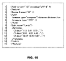
- FIG. 10 shows one example of an XML file of a template application rule and template information stored in a template database (DB).
- DB template database
- FIG. 11 shows an XML file tag structure of a file application rule and file information.
- FIG. 12 shows a flowchart of avatar's motion selection processing.
- FIGS. 13A to 13C show an example of causing an avatar to make motions along with a change in motions which a user makes to music.
- FIG. 14 shows a hardware configuration of the operational object controlling device according to the present embodiment.
- a preferred embodiment of the present invention provides an operational object controlling device that detects a motion of at least one part of the body of a user and selects a motion for an operational object according to the detected motion.
- the operational object controlling device includes a motion detection unit for detecting a motion of the user, a motion obtaining unit, a motion feature quantities extraction unit, a template, e.g., filter, storage unit, an operational object motion storage unit, a motion feature quantities transform unit and an operational object motion obtaining unit.
- the motion obtaining unit obtains the user's motion, which is detected by the motion detecting unit, for each predetermined interval.
- the motion feature quantities extraction unit extracts the user's motion feature quantities each of which is defined by one of the frequency components obtained by applying a Fourier transformation on a temporal sequence of the user's motions obtained by the motion obtaining unit.
- the template storage unit stores templates which weight the frequency components of the user's motion feature quantities.
- the operational object motion storage unit previously stores temporal motion sequences of the operational object.
- the motion feature quantities transform unit transforms the user's motion feature quantities, by use of a template that is obtained from the template storage unit according to environmental information of the user or the operational object.
- the operational object motion obtaining unit obtains a temporal motion sequence of the operational object that has motion feature quantities close to the user's motion feature quantities thus transformed, the motion feature quantities of the operational object being figured out based on each of the temporal motion sequences of the operational object previously stored in the operational object storage unit.
- the “operational object” here is an object operated by a user to perform motions. Typical examples of this are an avatar in a virtual world, and a robot in a real space. Also, the operational objects include human types as well as animal types and others.
- the “frequency transform” means to examine various frequency components included in temporal sequence values (temporal motion sequence value in the present invention), and the examples of the transform are the Fourier transformation and the Wavelet transform.
- the “environmental information” is composed of information on the user or the operational object and information on an environment where the user or the operational object exists, such as the information of a played musical piece, time, the sex and age of an avatar.
- the frequency components in the user's motion feature quantities are weighted according to the environmental information, by which the user's motion is modified and then is reflected in the motion of the operational object.
- “Modification” means to amplify or soften a particular motion of the user, such as making the particular motion larger or smaller.
- the operational object motion obtaining unit calculates a correlation coefficient between a temporal sequence dataset of each motion stored in the operational object motion storage unit, and temporal motion sequences obtained by performing an inverse frequency transform on the user's motion feature quantities with weight assigned to them by the motion feature quantities transform unit. Then, the operational object motion obtaining unit obtains the temporal motion sequences having the correlation coefficient closest to 1.0, e.g., unity, from among the temporal motion sequences stored in the operational object motion storage unit. By obtaining the temporal motion sequences of the operational object having the correlation coefficient closest to unity with the temporal motion sequences calculated from the weighted user's motion feature quantities, the operational object motion obtaining unit can identify the motion of the operational object close to the user's motion. Moreover, the motion feature quantities transform unit in an embodiment of the invention can use the template after performing the frequency transform on the template. Use of such template already processed by the frequency transform reduces the influence of frequency shift on the calculation result.
- Each of the motions of the operational object in an embodiment of the invention can be represented in a tree structure having at least one motion point.
- the motion point is, for example, a joint in the case where the operational object is an avatar, a robot or the like having a body structure similar to a human.
- Use of the tree structure including at least one motion point to represent the motion enables the expressing of a relationship between motion points and also the preparing of a flexible data structure with a high degree of scalability.
- the operational object motion storage unit and the template storage unit in an embodiment of the invention are relational databases or databases in the Extensible Markup Language (XML).
- XML Extensible Markup Language
- the environmental information of the user or the operational object is information on a musical piece played while the user performs motions
- the operational object controlling device further includes a music information storage unit for storing the information on the music.
- the information on the musical piece indicates, for example, a part of the musical piece such as “solo” and “chorus.”
- One of the templates is obtained according to the information on the musical piece, and thereby a user's motion can be modified to suit the musical piece to cause the operational object to perform the modified motion. For example, for the part of “chorus” that is an exciting part of the music, a template weighting high frequency components can be selected to make the motion more active.
- each of the predetermined intervals is determined as equivalent to one segment of a single measure of a musical piece.
- the segment is obtained by dividing the single measure by one or more. This allows each segment of a musical piece and its corresponding segment of the entire motions to coincide with each other, thereby preventing the operational object from performing motions out of the rhythms of music.
- an avatar is an operational object of a user in a virtual world.
- This description merely provides one example of the present invention.
- the technical scope of the present invention is not limited to this embodiment.
- the description of the embodiment of the present invention provides only some of the most preferable results of implementation of the present invention. Thus, the results of implementation of the present invention are not limited to those described in the embodiment or example of the present invention.
- the operational object controlling device 1 includes a user motion obtaining unit 10 , a motion feature value, e.g., quantities, extraction unit 11 , a music information obtaining unit 12 , a template searching unit 13 , a motion feature value, e.g., quantities, transform unit 14 , an avatar motion obtaining unit 15 , an avatar motion database (DB) 20 , a music DB 21 and an a template DB 22 .
- a motion feature value e.g., quantities, transform unit 14
- an avatar motion obtaining unit 15 e.g., an avatar motion database (DB) 20 , a music DB 21 and an a template DB 22 .
- the user motion obtaining unit 10 obtains a user's motions as three-dimensional absolute positions in temporal sequences through an input device (motion detector) such as a Wii Remote (trademark).
- an input device motion detector
- any device capable of obtaining three-dimensional absolute positions in temporal sequences can be used as the input device.
- One example of such devices is a device capable of calculating an absolute position through computation with an acceleration sensor.
- the motion feature quantities extraction unit 11 extracts the feature quantities of a user's motions by performing a frequency transform on temporal motion sequences obtained by the user motion obtaining unit 10 .
- the Fourier transformation is used for the frequency transform.
- the music information obtaining unit 12 obtains information on a musical piece currently played and information on the next measure of the musical piece, from the music DB 21 .
- the template searching unit 13 obtains template information from the template DB 22 according to the information obtained by the music information obtaining unit 12 .
- the motion feature quantities transform unit 14 weights frequency components of the motion feature quantities according to both the motion feature quantities extracted by the motion feature quantities extraction unit 11 , and the template information obtained by the template searching unit 13 .
- the avatar motion obtaining unit 15 calculates correlation coefficient between temporal motion sequences obtained through the inverse Fourier transformation of the motion feature quantities weighted by the motion feature quantities transform unit 14 , and each of temporal motion sequences in the avatar motion DB 20 , and obtains the temporal motion sequences having a correlation coefficient closest to unity, e.g. 1.0, in the avatar motion DB 20 .
- the avatar is displayed on a display or the like while performing a motion based on the obtained temporal motion sequences.
- the avatar motion DB 20 stores a temporal sequence of a continuous motion and its motion feature quantities for a specific number of frames, and accumulates multiple sets of the temporal motion sequences and feature quantities with respect to multiple types of motions of each part of the entire body of the avatar.
- the frame is a unit of sampling of the continuous motion. For example, one measure of a musical piece is divided into K segments and the motion is sampled at intervals of a 1/K measure for every frame. Thus, the number of frames is equivalent to one measure.
- each of the predetermined intervals at which the user's motion is obtained is equivalent to one segment of a single measure where the single measure is divided by an integer equal to at least one.
- the avatar motion DB 20 can be a relational DB in which information is expressed in a table format, or can be an XML DB in which information is expressed in XML. In this embodiment, the avatar motion DB 20 is an XML DB.
- the music DB 21 accumulatively stores music information on composers of respective musical pieces, and attribute information indicating an attribute such as “verse” for each measure of each of musical pieces, or a played time until the measure.
- the template DB 22 accumulatively stores template information on templates and rules for applying templates to the motion feature quantities.
- the template information is used to emphasize specific frequencies in the motion feature quantities.
- the music DB 21 can also be either a relational DB or an XML DB. In this embodiment, the music DB 21 is an XML DB.
- the user motion obtaining unit 10 is one example of a motion obtaining unit; the template searching unit 13 and the motion feature quantities transform unit 14 are one example of a motion feature quantities transform unit; the avatar motion obtaining unit 15 is one example of an operational object motion obtaining unit; the music DB 21 is one example of a music information storage unit; and the avatar motion DB 20 is one example of an operational object motion storage unit.
- each of the DBs can be a database on a hard disk, or can be prepared in an external storage device such as a memory. A hardware configuration of the operational object controlling device 1 will be described later.
- an avatar's motions are expressed in a Biovision Hierarchical Data, (BVH), file format that is one general motion data format and the avatar motion DB 20 is the XML DB conforming to the BVH format.
- the avatar's motion can be expressed in another format such as Acclaim Skeleton File and Acclaim Motion Capture (ASF/AMC) format.
- a relational DB can be used as the avatar motion DB 20 .
- the avatar motion DB 20 is composed of three items: skeleton data defining the skeleton structure and dimensions of an avatar; frame-based motion data defining an avatar's motion; and absolute coordinates and feature quantities of the motion data.
- the Skeleton data and the frame-based motion data are data pieces constituting a motion data set.
- a human body is expressed as an articulated link structure having multiple joints and bones.
- the motion data includes information on the length of each bone as well as time-series information on the position of each joint or time-series information on the angle of each joint.
- the avatar can be moved by use of the motion data.
- the absolute coordinates and feature quantities of the motion data are used to select a motion for the avatar, which will be described later.
- FIG. 2 shows one example of an XML file of skeleton data in the BVH format
- FIG. 3 shows an XML file tag structure of skeleton data in the BVH format.
- the skeleton structure and dimensions of an avatar are defined with ⁇ Root>, ⁇ Joint> and ⁇ End> under ⁇ Skeleton>.
- the skeleton tags in FIGS. 3 , 5 , 7 , and 11 are depicted in the figures without brackets.
- ⁇ Joint> denotes a joint node constituting a hierarchy structure, and has at least one ⁇ Joint> or ⁇ End> as a child node.
- ⁇ Root> denotes a special ⁇ Joint> serving as the sole starting point of the hierarchy structure, and has at least one ⁇ Joint> as a child node.
- ⁇ Root> defines the highest part of the hierarchy structure. If an object represents a person, a part representing the waist is generally defined as ⁇ Root>.
- ⁇ End> denotes a special ⁇ Joint> that is an end node of the hierarchy structure, and does not have any child node.
- ⁇ Root>, ⁇ Joint> and ⁇ End> each have a name attribute and an offset attribute.
- the name attribute specifies the name of a joint
- the offset attribute specifies the positions of x, y and z, in listed order, from the parent joint of ⁇ Root>.
- “Avatar” is set in name and the initial positions in the world coordinate system are set in offset.
- a joint name “v15” is defined in name, and the positions of x, y and z from ⁇ Root> are defined as (0.0000, 2.7700, 2.3300) in offset.
- joints are defined in the same way in ⁇ Joint>.
- the joints of ⁇ Joint> are defined in ascending order of the distance from ⁇ Root>.
- a joint name is defined as “skull_tip” and the positions from the Root are defined as (0.0000, 17.5290, 3.5690), in the same manner as ⁇ Joint>.
- ⁇ Joint> there is no definition of ⁇ Joint> below ⁇ End>.
- the same skeleton data in all the motion data accumulated in the avatar motion DB 20 , from the viewpoint of the data volume and the like. For this reason, when new motion data of an avatar is registered, and if the skeleton of the avatar performing the motion to be registered is different from the skeleton used in the avatar motion DB 20 , a scale factor of each joint in the skeleton of the avatar performing the motion to be registered is obtained with respect to the skeleton in the avatar motion DB 20 . Then, according to the obtained scale factors, the new avatar's motion data is scaled up or down to follow the skeleton in the avatar motion DB 20 . Then, the adjusted avatar's motion data is registered in the avatar motion DB 20 .
- the scale factor between the skeleton of the user's avatar and the skeleton in the avatar motion DB 20 is first obtained for each Joint in the same manner as in the above case of registering the motion data. Then, the motion data normalized to follow the skeleton in the avatar motion DB 20 are scaled up or down according to the obtained scale factors, and thus are adjusted to the avatar operated by the user.
- a conventional technique such as Dynamic Time Warping is used as this scaling technique.
- FIG. 4 shows one example of an XML file of motion data in the BVH format
- FIG. 5 shows an XML file tag structure of motion data in the BVH format.
- the postures of all joints of an avatar are defined with ⁇ Source>, ⁇ Skeleton>, ⁇ Root> and ⁇ Joint> frame by frame.
- ⁇ Source> specifies a source file format in a type attribute and the length of total data in a frame attribute.
- ⁇ Skeleton> is a skeleton information defining tag for specifying a corresponding file of skeleton data in a name attribute.
- xmlMotion_skeleton.xml is the name of a skeleton file corresponding to the motion data shown in FIG. 4 , that is, a skeleton file including the definition of the skeleton structure of an avatar operable by using the motion data shown in FIG. 4 .
- ⁇ Root> the position information and rotation information of ⁇ Root> are defined.
- the rotation information of each joint is stored in temporal sequences in a line direction.
- the joint information needs to conform to the skeleton data specified in ⁇ Skeleton>. This is because the joint information is motion data corresponding to the skeleton data specified in ⁇ Skeleton>.
- Any of the Euler angle representation, the Quaternion representation and the axis angle representation can be used as a method of representing the rotation information. In any of the representation methods, numerical values need to be given in the order of frames.
- ⁇ Position> is a Root position defining tag for defining ⁇ X>, ⁇ Y> and ⁇ Z>.
- ⁇ Rotation> is a Root pointing direction defining tag for defining any one of ⁇ Euler>, ⁇ Quaternion>, and ⁇ AxisAngle> tags.
- the pointing direction in the three-dimensional coordinate system is specified as rotation from a reference direction in the order of frames.
- the reference direction is defined in a way that the front direction is the +z direction, and that the gravity direction is the +y direction.
- ⁇ Euler> is an Euler representation defining tag including ⁇ X>, ⁇ Y> and ⁇ Z> for specifying Euler angles in a data attribute in the order of frames.
- the rotation matrices of ⁇ X>, ⁇ Y> and ⁇ Z> are multiplied in the order of specifying ⁇ X>, ⁇ Y> and ⁇ Z>.
- ⁇ Quaternion> is a Quaternion representation defining tag including ⁇ W>, ⁇ X>, ⁇ Y> and ⁇ Z> for specifying quaternions in data attributes in the order of frames.
- ⁇ AxisAngle> is an axis angle representation defining tag including ⁇ X>, ⁇ Y>, ⁇ V> and ⁇ Angle> for specifying three-dimensional vectors each representing a direction of a rotation axis, and rotation angles in data attributes in the order of frames.
- the pointing directions of the Root are defined with ⁇ Euler> in which the data attributes of ⁇ X>, ⁇ Y> and ⁇ Z> tags each indicate (0.0). This means that the Root points in the reference direction.
- ⁇ Joint> is a Joint rotation defining tag for defining any one of ⁇ Euler>, ⁇ Quaternion>, and ⁇ AxisAngle> tags.
- Tags included in any of the ⁇ Euler>, ⁇ Quaternion> and ⁇ AxisAngle> under ⁇ Joint> are similar to those under ⁇ Root>.
- the pointing directions of each joint in the three-dimensional coordinate system are specified, as a rotational movement from a reference direction, in the data attributes of ⁇ X>, ⁇ Y> and ⁇ Z> in the order of frames.
- the reference direction different directions are determined for respective joint parts. In general, the reference directions of the respective joints are determined based on the posture in which the avatar stands up with the arms hanging down.
- FIG. 6 shows one example of an XML file of absolute coordinates and feature quantities of motion data in the BVH format
- FIG. 7 shows an XML file tag structure of absolute coordinates and feature quantities of motion data in the BVH format.
- the absolute coordinates and motion feature quantities of motion data are defined with ⁇ Source>, ⁇ Motion> and ⁇ Joint> under ⁇ Feature>.
- ⁇ Source> is a Source information defining tag for specifying the number of dimensions of each motion feature quantities in a frame attribute. This number of dimensions is equal to the number of frames in its corresponding motion data in the case where the absolute coordinates are used.
- the corresponding motion data is defined in ⁇ Motion>. Assuming that the absolute coordinates and motion feature quantities in the motion data shown in FIG. 6 correspond to the motion data shown in FIG. 4 , the number of dimensions specified in the frame attribute in FIG. 6 is 2. This is the same as the number of frames in the motion data in FIG. 4 .
- ⁇ Motion> is a motion data defining tag for indicating a file name of its corresponding motion data in a name attribute.
- ⁇ Joint> is a node defining tag for specifying a joint name in a name attribute. This joint name needs to conform to the joint name in the corresponding motion data.
- ⁇ Spectrum> and ⁇ Position> are defined under ⁇ Joint>.
- ⁇ Spectrum> is a motion feature quantities defining tag for specifying the name of motion feature quantities in a type attribute and motion feature quantities in each of ⁇ X>, ⁇ Y> and ⁇ Z>. Since the motion feature quantities takes a complex number as a result of the Fourier transformation, a data 1 attribute indicates a real part whereas a data 2 attribute indicates an imaginary part.
- ⁇ Position> is an absolute coordinate defining tag for specifying a motion feature quantities name in a type attribute and the absolute coordinates in each of ⁇ X>, ⁇ Y> and ⁇ Z>.
- the absolute coordinates and feature quantities of the motion data can be figured out from the skeleton data defining the skeleton structure and dimensions of an avatar; and the frame-based motion data defining an avatar's motion. For this reason, the absolute coordinates and feature quantities of the motion data can be obtained, when needed, from the skeleton data defining the skeleton structure and dimensions of an avatar and the frame-based motion data defining an avatar's motion. However, this calculation takes some time. For this reason, it is desirable to calculate the absolute coordinates and feature quantities in advance and to store them in the avatar motion DB 20 .
- the avatar's motion is generally expressed not by absolute coordinates but by relationships among joints.
- the information obtained by the input device is expressed by absolute coordinates
- the user's motion feature quantities is a value calculated based on the absolute coordinates. Accordingly, in order to compare the user's and avatar's motion feature quantities with each other, it is necessary to obtain the avatar's motion feature quantities based on the absolute coordinates as will be described later. For this purpose, the absolute coordinates of the avatar's motions are obtained at the start of the process.
- the transform matrices used in Equation 1 are presented in Equations 2, 3 and 4 and a determinant of the parent joint vector (t x , t y , t z ) is presented in Equation 5.
- the absolute coordinates of a specific joint are obtained in the steps of:
- the motion feature quantities of absolute coordinates of an avatar will be described.
- the temporal motion sequences of the avatar are expressed in the three-dimensions of x, y, and z.
- a method for extracting feature quantities is described for each of the dimensions.
- a (a 0 , a 1 , . . . , a K-1 ) denotes a specific-dimensional temporal motion sequence, for example, of x coordinates in temporal motion sequences of K frames.
- K denotes the number of frames obtained by dividing one measure of a musical piece into K segments.
- the values A, B and C thus obtained are used as the motion feature quantities.
- the values A k , B k and C k are complex numbers, and the motion feature quantities are of three-dimensional temporal sequence data of the K frames. For this reason, an apparent number of feature quantities per motion is 2 ⁇ K ⁇ 3, but their degree of freedom is K ⁇ 3.
- the music DB 21 is not limited to an XML DB but can be a relational DB.
- the music DB 21 accumulatively stores MusicXML files in which attribute information such as “chorus” and “verse” is added to each measure or each played time.
- the MusicXML file is composed of three elements of “music information,” “play information” and “score information.”
- the music information indicates a title, composer and the like of each musical piece, the play information indicates information on an audio device and the like, and the score information indicates a score image and has notes and lyrics per measure written therein.
- FIG. 8 shows an example of a logical structure of MusicXML. As shown in FIG.
- FIG. 9 shows a part of MusicXML of a score.
- a type attribute is added to ⁇ measure> specifying a measure as shown in FIG. 9 , and the added type attribute indicates that this measure is “verse.”
- a number attribute indicates a sequential number of a measure. In FIG. 9 , the number attribute indicates that the measure is the first measure.
- an annotation can be added to a musical piece at a particularly-specified time point, by attaching time line information as in Timeline Annotator to the time line of information in XML format used in iTunes (trademark) such as iTunes Music Library.xml.
- the template DB 22 is an XML DB is not limited to an XML DB but can be a relational DB.
- the template DB 22 accumulatively stores XML files of template application rules and template information.
- FIG. 10 shows one example of an XML file of a template application rule and template information stored in the template DB 22 .
- FIG. 11 shows an XML file tag structure of a file application rule and file information. As shown in FIG. 11 , ⁇ Source>, ⁇ Rule> and ⁇ Joint> are defined under ⁇ Feature> to specify a template application rule and template information.
- ⁇ Source> is a Source information defining tag for specifying the number of dimensions of a template in a frame attribute.
- ⁇ Rule> is a tag for specifying music information targeted for a rule application, and uses type attributes to define tags for a format of music information and an element of the music information.
- a motion feature quantities defining tag ⁇ Template> is defined, and the template information for motion feature quantities is defined in a type attribute of each of ⁇ X>, ⁇ Y> and ⁇ Z>.
- the relationship between ⁇ Joint> and ⁇ Template> is the same as that between ⁇ Joint> and ⁇ Spectrum> of the motion feature quantities stored in the avatar motion DB 20 .
- the XML file shown in FIG. 10 is one example of a template applied to a musical piece composed by Johannes Brahms at a measure defined as “verse.”
- the composer name and the music part “verse” are specified on the 5th and 6th lines.
- the name attribute of ⁇ Joint> on line 8 indicates that the XML file is applied to the joint “l_wrist.”
- Possible template application examples for weighting frequency components of motion feature quantities are: to emphasize low frequency components for a musical part such as “solo” where relatively mild motions are more suitable; and to emphasize both high and low frequency components for a musical part such as “chorus” where exciting and energetic motions are more suitable.
- FIG. 12 shows a flowchart of avatar's motion selection processing.
- the avatar's motion selection processing starts once a musical piece starts.
- the user motion obtaining unit 10 obtains temporal motion sequences of a user from an input device.
- the description is provided, for example, based on the case where a Wii Remote (trademark) is used as the input device.
- the Wii Remote is equipped with a CMOS image sensor in its front edge, and is used in combination with a horizontally-long bar-like device, called a sensor bar, which has five infrared LEDs incorporated at both ends.
- the image sensor senses two light spots from both ends of the sensor bar.
- a pointing direction in which the Wii Remote points to the television screen, and a distance between the Wii Remote and the television screen can be calculated based on the positional relationship and distance between the sensed two light spots.
- the user motion obtaining unit 10 obtains, as a user's motion, the pointing direction of the Wii Remote and the distance from the Wii Remote, which are thus calculated.
- a motion such as a rotation is obtained using two or more devices by specifying in advance which part of the body is assigned to each of the devices (when two devices are held with the right and left hands. The device on the left hand side remains in left hand, and the device held with the right hand is dedicated to the right hand, etc. If more input devices are respectively assigned to more parts of the body, the motion of each of the parts of the user's body can be reflected in a motion of the corresponding part of the avatar's body. In this case, it is necessary to specify correspondences between devices and parts of a user's body, respectively, before actual use. In addition, temporal motion sequences and motion feature quantities need to be defined for each part of the body in the avatar motion DB 20 .
- the user motion obtaining unit 10 samples the motions not at specific fixed intervals, but at intervals of a 1/K measure (resulting from division of one measure into K segments). This measure dividing number K needs to be equal to the number of dimensions or frames in the avatar motion DB 20 and the template DB 22 .
- the motion feature quantities extraction unit 11 obtains user's motion feature quantities from the temporal sequence of the user's motions obtained in step S 1 .
- the user's motion feature quantities are obtained through the Fourier transformation shown in Equation 6 in the same manner of obtaining the foregoing avatar's motion feature quantities.
- step S 3 from the music DB 21 , the music information obtaining unit 12 obtains information on the measure next to a currently played measure and its music information.
- the music information is obtained by use of a conventional technique.
- Obtaining the information on the measure next to a currently played measure means to obtain the information indicating that the next measure is a measure of “verse,” for example when a measure of “solo” is currently played.
- Such obtaining is necessary because the avatar performs a motion, which is selected based on a user's motion obtained in step S 1 by use of the information obtained in step S 3 , at a time point sometime after the user's motion is obtained.
- the template searching unit 13 searches the template DB 22 to obtain templates (step S 4 ). Since the template DB 22 is the XML DB as described above, XQuery or the like is used for the search. In the case where two or more search results are obtained, a template is determined in any method, such as selecting a template at random or using the average of the search results to select a template.
- the template obtained in step S 3 is applied to the user's motion feature quantities obtained in Step S 2 (step S 5 ).
- X, Y and Z denote the user's motion feature quantities for the axes X, Y and Z, respectively
- ⁇ , ⁇ and ⁇ denote templates for the axes X, Y and Z, respectively.
- the frequency components in the X axis direction, which are desired to be emphasized, can be emphasized according to Equation 7.
- X′, Y′ and Z′ are obtained.
- X′, Y′ and Z′ obtained in step S 5 are subjected to the inverse Fourier transformation for the frequency domain (step S 6 ).
- the avatar's motion selection processing involves: performing the Fourier transformation on the temporal sequence of the user's motions; applying the templates to the resultant temporal sequence of the user's motions; performing the inverse Fourier transformation on the template processed, e.g., filtered, temporal sequence of the user's motions; and calculating correlations between the resultant temporal sequence of the user's motions and the avatar's temporal motion sequences.
- the template processed e.g., filtered, temporal sequence of the user's motions
- correlations between the resultant temporal sequence of the user's motions and the avatar's temporal motion sequences Besides this processing, there is processing for selecting a suitable avatar's motion even when a frequency shift occurs.
- This processing involves: performing the Fourier transformation on the temporal sequence of the user's motions; performing the Fourier transformation on the templates, similarly; applying the resultant templates to the resultant temporal sequence of the user's motions; performing the inverse Fourier transformation on the template processed temporal sequence of the user's motions; and calculating correlations between the resultant temporal sequence of the user's motions and the avatar's temporal motion sequences.
- the processing uses feature quantities A i , B i and C i for the respective axes prestored in the avatar motion DB 20 .
- clustering of the avatar's motions can be effective. More specifically, the avatar's motions are first classified into clusters in temporal sequences, and the median value of each cluster is obtained. Then, one cluster is selected according to the correlation coefficients respectively calculated with the motion feature quantities of the temporal motion sequences having the medium values of the clusters. Thereafter, temporal motion sequences in the selected cluster having the correlation coefficient closest to unity are searched out again.
- FIGS. 13A to 13C show an example of causing an avatar to perform motions along with a change in motions which a user performs to music.
- FIG. 13A shows that the user dances while holding an input device with the right hand and moving the right hand up and down.
- the music is exciting in the “chorus”
- the high frequency components of the user's motion feature quantities are weighted by the templates to select motions in which the avatar moves the right hand energetically up and down as shown in FIG. 13B .
- the low frequency components of the user's motion feature quantities are weighted by the templates to select motions in which the avatar moves the right hand moderately up and down as shown in FIG. 13C .
- FIG. 14 shows a hardware configuration of the operational object controlling device 1 according to the present embodiment.
- the operational object controlling device 1 includes a central processing unit (CPU) 310 constituting a controller 300 , a bus line 200 , a communication interface (I/F) 320 , a main memory 330 , a basic input output system (BIOS) 340 , a display device 350 , an input/output (I/O) controller 360 , an input device 370 such as a keyboard and mouse, a hard disk 380 , an optical disc drive 390 , and a semiconductor memory 410 .
- the hard disk 380 , the optical disc drive 390 and the semiconductor memory 410 are collectively called a storage device 420 .
- the controller 300 is a unit for controlling the operational object controlling device 1 overall, and reads and executes various programs stored in the hard disk 380 as needed to implement various functions according to the embodiment of the present invention while collaborating with the described hardware.
- the communication I/F 320 is a network adapter for allowing the operational object controlling device 1 to receive and transmit information from and to other devices through a communication network.
- the communication I/F 320 can include a modem, a cable modem and Ethernet (trade mark) adapter. However, if the operational object controlling device 1 does not perform communications, the communication I/F 320 is not needed.
- the BIOS 340 stores a boot program to be executed by the CPU 310 at the start-up time of the operational object controlling device 1 , a hardware-dependant program of the operational object controlling device 1 , and other programs.
- the display device 350 includes a display device such as a cathode-ray tube display device (CRT) or a liquid crystal display device.
- a display device such as a cathode-ray tube display device (CRT) or a liquid crystal display device.
- the storage device 420 such as the hard disk 380 , the optical disc drive 390 and the semiconductor memory 410 can be connected to the I/O controller 360 .
- the input device 370 is for inputting a user's motions and is equivalent to a motion detecting unit.
- the hard disk 380 stores various programs for causing the hardware to function as the operational object controlling device 1 , a program for implementing the functions of the present invention, and tables and records.
- the operational object controlling device 1 can use as an external storage device a hard disk (not shown) additionally installed outside the device 1 .
- a DVD-ROM drive, a CD-ROM drive, a DVD-RAM drive or a CD-RAM drive, for example, can be used in place of the optical disc drive 390 .
- the disc 400 corresponding to each of the drives is used. It is also possible to provide a program or data to the main memory 330 or the hard disk 380 through the I/O controller 360 after reading the program or data from the optical disc 400 through the optical disc drive 390 .
- a computer in this present invention is an information processing apparatus including the storage device 420 , the CPU 310 and the like, and that the operational object controlling device 1 is configured as an information processing apparatus including the storage device 420 , the CPU 310 and the like.
- This information processing apparatus corresponds to the computer of the embodiment of the present invention.
- the operational object controlling device 1 can be implemented by use of any of various terminals such as a mobile phone, a PDA (personal data assistant) and a gaming device as long as the principle of the embodiment of the present invention is applicable to the terminal.
- an operational object controlling device and method that are capable of easily reflecting a user's motions in motions of an operational object after modifying the user's motions, thereby allowing the user to feel united with the operational object, and causing the operational object to perform various motions.
Landscapes
- Engineering & Computer Science (AREA)
- General Engineering & Computer Science (AREA)
- Theoretical Computer Science (AREA)
- Human Computer Interaction (AREA)
- Physics & Mathematics (AREA)
- General Physics & Mathematics (AREA)
- Processing Or Creating Images (AREA)
Abstract
Description
X′ k=αk X k (k=0,1 . . . , K−1)
X′, Y′ and Z′ obtained in step S5 are subjected to the inverse Fourier transformation for the frequency domain (step S6). For example, the inverse Fourier transformation for xi′=(x′0, x′1, . . . , x′K-1) is expressed as
Claims (19)
Applications Claiming Priority (2)
| Application Number | Priority Date | Filing Date | Title |
|---|---|---|---|
| JP2008113241A JP5495222B2 (en) | 2008-04-23 | 2008-04-23 | Operation object control device, system, method and program |
| JP2008-113241 | 2008-04-23 |
Publications (2)
| Publication Number | Publication Date |
|---|---|
| US20090267894A1 US20090267894A1 (en) | 2009-10-29 |
| US8416185B2 true US8416185B2 (en) | 2013-04-09 |
Family
ID=41214521
Family Applications (1)
| Application Number | Title | Priority Date | Filing Date |
|---|---|---|---|
| US12/428,523 Expired - Fee Related US8416185B2 (en) | 2008-04-23 | 2009-04-23 | Operational object controlling device, system, method and program |
Country Status (2)
| Country | Link |
|---|---|
| US (1) | US8416185B2 (en) |
| JP (1) | JP5495222B2 (en) |
Cited By (1)
| Publication number | Priority date | Publication date | Assignee | Title |
|---|---|---|---|---|
| US8989521B1 (en) * | 2011-11-23 | 2015-03-24 | Google Inc. | Determination of dance steps based on media content |
Families Citing this family (6)
| Publication number | Priority date | Publication date | Assignee | Title |
|---|---|---|---|---|
| US8334842B2 (en) * | 2010-01-15 | 2012-12-18 | Microsoft Corporation | Recognizing user intent in motion capture system |
| KR101189633B1 (en) * | 2011-08-22 | 2012-10-10 | 성균관대학교산학협력단 | A method for recognizing ponter control commands based on finger motions on the mobile device and a mobile device which controls ponter based on finger motions |
| US20150095822A1 (en) * | 2012-07-02 | 2015-04-02 | eScoreMusic, Inc. | Systems and methods for music display, collaboration, annotation, composition, and editing |
| JP6287921B2 (en) * | 2015-03-25 | 2018-03-07 | ブラザー工業株式会社 | Information processing apparatus and program |
| GB201621434D0 (en) * | 2016-12-16 | 2017-02-01 | Palantir Technologies Inc | Processing sensor logs |
| JP6699677B2 (en) * | 2018-02-06 | 2020-05-27 | ヤマハ株式会社 | Information processing method, information processing apparatus, and program |
Citations (4)
| Publication number | Priority date | Publication date | Assignee | Title |
|---|---|---|---|---|
| JP2001276291A (en) | 2000-03-31 | 2001-10-09 | Daiichikosho Co Ltd | Dance game system |
| JP2002042168A (en) | 2000-07-31 | 2002-02-08 | Taito Corp | Dance image enhancement composition device |
| JP2005297095A (en) | 2004-04-07 | 2005-10-27 | Sony Corp | Robot apparatus and operation comparison method thereof |
| US7049608B2 (en) * | 2001-05-29 | 2006-05-23 | Advantest Corp. | Position detection apparatus, position detection method, electronic part carrying apparatus, and electronic beam exposure apparatus |
Family Cites Families (3)
| Publication number | Priority date | Publication date | Assignee | Title |
|---|---|---|---|---|
| JP3368739B2 (en) * | 1996-01-22 | 2003-01-20 | 三菱電機株式会社 | Animation production system |
| JP2000288253A (en) * | 1999-04-07 | 2000-10-17 | Enix Corp | Video game device and recording medium storing program |
| JP2001299975A (en) * | 2000-04-27 | 2001-10-30 | Hiromi Hamabe | Bodily sensing device and bodily sensing system |
-
2008
- 2008-04-23 JP JP2008113241A patent/JP5495222B2/en active Active
-
2009
- 2009-04-23 US US12/428,523 patent/US8416185B2/en not_active Expired - Fee Related
Patent Citations (4)
| Publication number | Priority date | Publication date | Assignee | Title |
|---|---|---|---|---|
| JP2001276291A (en) | 2000-03-31 | 2001-10-09 | Daiichikosho Co Ltd | Dance game system |
| JP2002042168A (en) | 2000-07-31 | 2002-02-08 | Taito Corp | Dance image enhancement composition device |
| US7049608B2 (en) * | 2001-05-29 | 2006-05-23 | Advantest Corp. | Position detection apparatus, position detection method, electronic part carrying apparatus, and electronic beam exposure apparatus |
| JP2005297095A (en) | 2004-04-07 | 2005-10-27 | Sony Corp | Robot apparatus and operation comparison method thereof |
Cited By (1)
| Publication number | Priority date | Publication date | Assignee | Title |
|---|---|---|---|---|
| US8989521B1 (en) * | 2011-11-23 | 2015-03-24 | Google Inc. | Determination of dance steps based on media content |
Also Published As
| Publication number | Publication date |
|---|---|
| US20090267894A1 (en) | 2009-10-29 |
| JP5495222B2 (en) | 2014-05-21 |
| JP2009261533A (en) | 2009-11-12 |
Similar Documents
| Publication | Publication Date | Title |
|---|---|---|
| US8416185B2 (en) | Operational object controlling device, system, method and program | |
| Smith et al. | Efficient neural networks for real-time motion style transfer | |
| Raptis et al. | Real-time classification of dance gestures from skeleton animation | |
| KR101671900B1 (en) | System and method for control of object in virtual world and computer-readable recording medium | |
| CN115244495B (en) | Real-time style for virtual environment motion | |
| Egges et al. | Personalised real-time idle motion synthesis | |
| JP4489825B2 (en) | Gesture input system, method and program | |
| JP5902204B2 (en) | Motion recognition | |
| CN105228708B (en) | Body motion scoring device, dance scoring device, karaoke device and game device | |
| Jensenius | Methods for studying music-related body motion | |
| KR20010081193A (en) | 3D virtual reality motion capture dance game machine by applying to motion capture method | |
| Garcia et al. | Spatial motion doodles: Sketching animation in vr using hand gestures and laban motion analysis | |
| Tilmanne et al. | Stylistic gait synthesis based on hidden Markov models | |
| Aristidou et al. | Feature extraction for human motion indexing of acted dance performances | |
| JP2001134615A (en) | Method and device for retrieving three-dimensional human body posture | |
| CN111353347B (en) | Action recognition error correction method, electronic device, storage medium | |
| Sankhla et al. | Automated translation of human postures from kinect data to labanotation | |
| Hachaj et al. | RMoCap: an R language package for processing and kinematic analyzing motion capture data | |
| CN111353345B (en) | Method, device, system, electronic device, and storage medium for providing training feedback | |
| Wang | Simulation of athlete gait recognition based on spectral features and machine learning | |
| Krüger et al. | Multi-mode tensor representation of motion data | |
| Han et al. | Connecting users to virtual worlds within MPEG-V standardization | |
| JP2018128947A (en) | CG generation apparatus and program | |
| 김성훈 et al. | Partial movement authoring for a reconfigurable motion capture | |
| WO2023032422A1 (en) | Processing method, program, and processing device |
Legal Events
| Date | Code | Title | Description |
|---|---|---|---|
| AS | Assignment |
Owner name: INTERNATIONAL BUSINESS MACHINES CORPORATION, NEW Y Free format text: ASSIGNMENT OF ASSIGNORS INTEREST;ASSIGNORS:DOI, JUN;FUJIWARA, KAORI;TATSUBORI, MICHIAKI;REEL/FRAME:022585/0644;SIGNING DATES FROM 20090403 TO 20090419 Owner name: INTERNATIONAL BUSINESS MACHINES CORPORATION, NEW Y Free format text: ASSIGNMENT OF ASSIGNORS INTEREST;ASSIGNORS:DOI, JUN;FUJIWARA, KAORI;TATSUBORI, MICHIAKI;SIGNING DATES FROM 20090403 TO 20090419;REEL/FRAME:022585/0644 |
|
| STCF | Information on status: patent grant |
Free format text: PATENTED CASE |
|
| FPAY | Fee payment |
Year of fee payment: 4 |
|
| MAFP | Maintenance fee payment |
Free format text: PAYMENT OF MAINTENANCE FEE, 8TH YEAR, LARGE ENTITY (ORIGINAL EVENT CODE: M1552); ENTITY STATUS OF PATENT OWNER: LARGE ENTITY Year of fee payment: 8 |
|
| FEPP | Fee payment procedure |
Free format text: MAINTENANCE FEE REMINDER MAILED (ORIGINAL EVENT CODE: REM.); ENTITY STATUS OF PATENT OWNER: LARGE ENTITY |
|
| LAPS | Lapse for failure to pay maintenance fees |
Free format text: PATENT EXPIRED FOR FAILURE TO PAY MAINTENANCE FEES (ORIGINAL EVENT CODE: EXP.); ENTITY STATUS OF PATENT OWNER: LARGE ENTITY |
|
| STCH | Information on status: patent discontinuation |
Free format text: PATENT EXPIRED DUE TO NONPAYMENT OF MAINTENANCE FEES UNDER 37 CFR 1.362 |
|
| FP | Lapsed due to failure to pay maintenance fee |
Effective date: 20250409 |