US8400550B2 - Camera-equipped electronic device - Google Patents
Camera-equipped electronic device Download PDFInfo
- Publication number
- US8400550B2 US8400550B2 US11/991,565 US99156506A US8400550B2 US 8400550 B2 US8400550 B2 US 8400550B2 US 99156506 A US99156506 A US 99156506A US 8400550 B2 US8400550 B2 US 8400550B2
- Authority
- US
- United States
- Prior art keywords
- unit
- camera
- electronic device
- photographic
- mode
- Prior art date
- Legal status (The legal status is an assumption and is not a legal conclusion. Google has not performed a legal analysis and makes no representation as to the accuracy of the status listed.)
- Expired - Fee Related, expires
Links
Images


Classifications
-
- H—ELECTRICITY
- H04—ELECTRIC COMMUNICATION TECHNIQUE
- H04N—PICTORIAL COMMUNICATION, e.g. TELEVISION
- H04N5/00—Details of television systems
- H04N5/76—Television signal recording
- H04N5/765—Interface circuits between an apparatus for recording and another apparatus
- H04N5/77—Interface circuits between an apparatus for recording and another apparatus between a recording apparatus and a television camera
- H04N5/772—Interface circuits between an apparatus for recording and another apparatus between a recording apparatus and a television camera the recording apparatus and the television camera being placed in the same enclosure
-
- H—ELECTRICITY
- H04—ELECTRIC COMMUNICATION TECHNIQUE
- H04N—PICTORIAL COMMUNICATION, e.g. TELEVISION
- H04N1/00—Scanning, transmission or reproduction of documents or the like, e.g. facsimile transmission; Details thereof
- H04N1/00885—Power supply means, e.g. arrangements for the control of power supply to the apparatus or components thereof
- H04N1/00899—Detection of supply level or supply failure
-
- H—ELECTRICITY
- H04—ELECTRIC COMMUNICATION TECHNIQUE
- H04N—PICTORIAL COMMUNICATION, e.g. TELEVISION
- H04N21/00—Selective content distribution, e.g. interactive television or video on demand [VOD]
- H04N21/40—Client devices specifically adapted for the reception of or interaction with content, e.g. set-top-box [STB]; Operations thereof
- H04N21/41—Structure of client; Structure of client peripherals
- H04N21/418—External card to be used in combination with the client device, e.g. for conditional access
- H04N21/4184—External card to be used in combination with the client device, e.g. for conditional access providing storage capabilities, e.g. memory stick
-
- H—ELECTRICITY
- H04—ELECTRIC COMMUNICATION TECHNIQUE
- H04N—PICTORIAL COMMUNICATION, e.g. TELEVISION
- H04N21/00—Selective content distribution, e.g. interactive television or video on demand [VOD]
- H04N21/40—Client devices specifically adapted for the reception of or interaction with content, e.g. set-top-box [STB]; Operations thereof
- H04N21/41—Structure of client; Structure of client peripherals
- H04N21/422—Input-only peripherals, i.e. input devices connected to specially adapted client devices, e.g. global positioning system [GPS]
- H04N21/4223—Cameras
-
- H—ELECTRICITY
- H04—ELECTRIC COMMUNICATION TECHNIQUE
- H04N—PICTORIAL COMMUNICATION, e.g. TELEVISION
- H04N21/00—Selective content distribution, e.g. interactive television or video on demand [VOD]
- H04N21/40—Client devices specifically adapted for the reception of or interaction with content, e.g. set-top-box [STB]; Operations thereof
- H04N21/43—Processing of content or additional data, e.g. demultiplexing additional data from a digital video stream; Elementary client operations, e.g. monitoring of home network or synchronising decoder's clock; Client middleware
- H04N21/433—Content storage operation, e.g. storage operation in response to a pause request, caching operations
- H04N21/4334—Recording operations
-
- H—ELECTRICITY
- H04—ELECTRIC COMMUNICATION TECHNIQUE
- H04N—PICTORIAL COMMUNICATION, e.g. TELEVISION
- H04N21/00—Selective content distribution, e.g. interactive television or video on demand [VOD]
- H04N21/40—Client devices specifically adapted for the reception of or interaction with content, e.g. set-top-box [STB]; Operations thereof
- H04N21/43—Processing of content or additional data, e.g. demultiplexing additional data from a digital video stream; Elementary client operations, e.g. monitoring of home network or synchronising decoder's clock; Client middleware
- H04N21/443—OS processes, e.g. booting an STB, implementing a Java virtual machine in an STB or power management in an STB
- H04N21/4436—Power management, e.g. shutting down unused components of the receiver
-
- H—ELECTRICITY
- H04—ELECTRIC COMMUNICATION TECHNIQUE
- H04N—PICTORIAL COMMUNICATION, e.g. TELEVISION
- H04N23/00—Cameras or camera modules comprising electronic image sensors; Control thereof
- H04N23/60—Control of cameras or camera modules
- H04N23/63—Control of cameras or camera modules by using electronic viewfinders
- H04N23/633—Control of cameras or camera modules by using electronic viewfinders for displaying additional information relating to control or operation of the camera
-
- H—ELECTRICITY
- H04—ELECTRIC COMMUNICATION TECHNIQUE
- H04N—PICTORIAL COMMUNICATION, e.g. TELEVISION
- H04N23/00—Cameras or camera modules comprising electronic image sensors; Control thereof
- H04N23/60—Control of cameras or camera modules
- H04N23/65—Control of camera operation in relation to power supply
- H04N23/651—Control of camera operation in relation to power supply for reducing power consumption by affecting camera operations, e.g. sleep mode, hibernation mode or power off of selective parts of the camera
-
- H—ELECTRICITY
- H04—ELECTRIC COMMUNICATION TECHNIQUE
- H04N—PICTORIAL COMMUNICATION, e.g. TELEVISION
- H04N5/00—Details of television systems
- H04N5/44—Receiver circuitry for the reception of television signals according to analogue transmission standards
-
- H—ELECTRICITY
- H04—ELECTRIC COMMUNICATION TECHNIQUE
- H04N—PICTORIAL COMMUNICATION, e.g. TELEVISION
- H04N2201/00—Indexing scheme relating to scanning, transmission or reproduction of documents or the like, and to details thereof
- H04N2201/0008—Connection or combination of a still picture apparatus with another apparatus
- H04N2201/001—Sharing resources, e.g. processing power or memory, with a connected apparatus or enhancing the capability of the still picture apparatus
-
- H—ELECTRICITY
- H04—ELECTRIC COMMUNICATION TECHNIQUE
- H04N—PICTORIAL COMMUNICATION, e.g. TELEVISION
- H04N2201/00—Indexing scheme relating to scanning, transmission or reproduction of documents or the like, and to details thereof
- H04N2201/0008—Connection or combination of a still picture apparatus with another apparatus
- H04N2201/0013—Arrangements for the control of the connected apparatus by the still picture apparatus
-
- H—ELECTRICITY
- H04—ELECTRIC COMMUNICATION TECHNIQUE
- H04N—PICTORIAL COMMUNICATION, e.g. TELEVISION
- H04N2201/00—Indexing scheme relating to scanning, transmission or reproduction of documents or the like, and to details thereof
- H04N2201/0077—Types of the still picture apparatus
- H04N2201/0084—Digital still camera
-
- H—ELECTRICITY
- H04—ELECTRIC COMMUNICATION TECHNIQUE
- H04N—PICTORIAL COMMUNICATION, e.g. TELEVISION
- H04N5/00—Details of television systems
- H04N5/76—Television signal recording
- H04N5/907—Television signal recording using static stores, e.g. storage tubes or semiconductor memories
Definitions
- the present invention relates to a camera-equipped electronic device having functions other than a photographing function, such as functions of receiving and displaying TV broadcasts.
- Patent reference literature 1 discloses such a digital camera with a built-in TV tuner so as to allow the user to view television broadcasts.
- a camera-equipped electronic device comprises a photographic unit that stores in a storage medium an image obtained by photographing a subject via an imaging unit; a non-photographic unit that executes non-photographing processing different from photographing processing executed in the photographic unit and requires greater electric power than is required by the photographing processing; a decision-making unit that makes a decision as to whether or not a current state of use is such that if the non-photographic unit is engaged in operation over a predetermined length of time, remaining battery capacity will be depleted to a level equal to or less than a predetermined value; and a restricting unit that imposes restrictions on a use of the non-photographic unit with regard to consumption of the electric power based upon results of the decision made by the decision-making unit.
- the decision-making unit includes a detection unit that detects a state of the storage medium; and the restricting unit restricts the use of the non-photographic unit with regard to the consumption of the electric power in correspondence to the detected state of the storage medium.
- the detection unit detects the presence of the storage medium loaded in the camera-equipped electronic device; and the restricting unit restricts the use of the non-photographic unit if the presence of the storage medium loaded in the camera-equipped electronic device is not detected.
- the decision-making unit includes a mode selector unit that selects one of a user mode and a non-user mode; and the restricting unit restricts the use of the non-photographic unit when the non-user mode has been selected.
- the decision-making unit includes a detection unit that detects the presence of the storage medium loaded in the camera-equipped electronic device; and the restricting unit restricts the use of the non-photographic unit when the user mode has been selected and the presence of the storage medium loaded in the camera-equipped electronic device is detected.
- a mode selector unit that selects one of a user mode and a non-user mode, and the detection unit detects the presence of the storage medium loaded in the camera-equipped electronic device; and the restricting unit restricts the use of the non-photographic unit when the user mode has been selected and the presence of the storage medium loaded in the camera-equipped electronic device is detected.
- a mode selector unit that selects one of a user mode and a non-user mode
- the detection unit includes a capacity detection unit that detects a remaining storage capacity available in the storage medium; and when the user mode has been selected and the detected remaining storage capacity available at the storage medium is equal to or less than a reference value, the restricting unit does not restrict the use of the non-photographic unit, whereas when the non-user mode has been selected, the restricting unit restricts the use of the non-photographic unit regardless of the detected remaining storage capacity available at the storage medium.
- the decision-making unit includes a power supply detection unit that detects whether or not electric power is being supplied to the camera-equipped electronic device from an external power source; and the restricting unit restricts the use of the non-photographic unit with regard to consumption of the electric power when the power supply detection unit detects that no electric power is being supplied to the camera-equipped electronic device from the external power source.
- the camera-equipped electronic device in the camera-equipped electronic device according to the eighth aspect, it is preferred that there is further provided a state detection unit that detects the presence of the storage medium loaded in the camera-equipped electronic device, and the restricting unit does not restrict the use of the non-photographic unit when the state detection unit does not detect the presence of the storage medium loaded in the camera-equipped electronic device.
- the restricting unit does not restrict the use of the non-photographic unit with regard to the consumption of the electric power when the power supply detection unit detects that electric power is being supplied from the external power source to the camera-equipped electronic device.
- the camera-equipped electronic device in the camera-equipped electronic device according to any of the first through the tenth aspect, it is preferred that there is further provided a selection unit that selects one of the photographic unit and the non-photographic unit, and the restricting unit imposes restrictions on the use of the non-photographic unit on condition that the non-photographic unit has been selected by the selection unit.
- the restricting unit performs one of allowance of the non-photographic unit to be engaged in operation over only a predetermined length of time and disallowance of engagement of a specific function among a plurality of functions of the non-photographic unit.
- the non-photographic unit is at least one of a television unit and a projector.
- FIG. 1 External views of a TV tuner-equipped digital camera with a according to the present invention, with (a) presenting a top view and (b) presenting a rear view
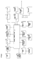
- FIG. 2 A block diagram of the TV tuner-equipped digital camera according to the present invention
- FIG. 3 A flowchart of the operations executed in the TV tuner-equipped digital camera in a first embodiment of the present invention
- FIG. 4 A flowchart of the operations executed in the TV tuner-equipped digital camera in a second embodiment of the present invention
- FIG. 5 A block diagram of a projector-equipped digital camera according to the present invention
- FIG. 6 A flowchart of the operations executed in the projector-equipped digital camera according to the present invention
- FIG. 7 A flowchart of the operations executed in the TV tuner-equipped digital camera in a fourth embodiment of the present invention
- FIG. 8 A block diagram of the essential structure adopted in a TV tuner/projector-equipped digital camera according to the present invention
- FIG. 9 A flowchart of the operations executed in the TV tuner/projector-equipped digital camera
- FIG. 10 A block diagram of the essential structure adopted in the TV tuner-equipped digital camera in a sixth embodiment of the present invention
- FIG. 11 A flowchart of the operations executed in the TV tuner-equipped digital camera in the sixth embodiment of the present invention
- FIG. 1 provides external views of the TV tuner-equipped digital camera according to the present invention
- FIG. 2 provides a block diagram of the TV tuner-equipped digital camera.
- An object of the first embodiment is to limit the length of time over which a television broadcast can be viewed at a retail shop.
- the digital camera is judged to be in a retail store mode when a memory card is loaded therein.
- the TV tuner-equipped digital camera has a digital camera function and a TV tuner function. It is to be noted that the elements engaged in operation primarily to fulfill these functions are collectively referred to as a digital camera unit and a TV tuner unit.
- the digital camera unit includes a lens 14 , an image sensor 15 , a typical example of which is a CCD sensor or a CMOS sensor, a shutter release button switch 10 operated by the user, a cross key 18 operated by the user to select various settings, an built-in memory 16 where a captured image is temporarily stored, an overall control unit 19 that includes a CPU and its peripheral circuits engaged in operation to execute various types of photographing control and execute image composite processing to be detailed later, a liquid crystal monitor 11 at which a reproduced photographic image, a through image or various settings menus are displayed with a backlight (not shown), and a memory card slot 12 a at which a memory card 12 having saved therein captured images together with image capturing time information indicating times counted via a time counter circuit 102 .
- the liquid crystal monitor 11 may be constituted with a light emitting element such as an organic EL (electroluminescence) element.
- a memory card 12 may assume any form as long as it is a recording medium that can be detachably loaded into the camera body.
- Reference numeral 13 indicates a battery
- reference numeral 31 indicates an A/D conversion circuit
- reference numeral 32 indicates a correction circuit
- reference numeral 33 indicates a memory
- reference numeral 34 indicates a card I/F
- reference numeral 35 indicates an external I/F.
- a signal (card detection signal) indicating the presence/absence of a card in the memory card slot 12 a is input to the overall control unit 19 via the card I/F 34 .
- a menu button 100 operated to bring up a setting menu at the liquid crystal monitor 11 and a display button 101 operated to bring up on display at the liquid crystal monitor 11 the newest photographic image most recently stored in the built-in memory 16 are disposed.
- the TV tuner unit includes a tuner 21 , an antenna 22 , a processing circuit 23 that digitally processes the video signal in a received television broadcast, a speaker 26 through which the television broadcast sound is output and an amplifier 25 that amplifies the sound.
- the TV tuner unit shares with the digital camera unit the overall control unit 19 which also executes various types of control related to the television broadcast, the liquid crystal monitor 11 at which the received television image is displayed, and the cross key 18 .
- an operation unit 20 in FIG. 2 represents various operation members including the cross key 18 . In a camera mode, the cross key 18 is used as the zoom button and the like, whereas it is used in a television mode for selecting a channel and adjusting the volume.
- the operation unit 20 in this embodiment includes a mode selector switch 24 with which a changeover operation is performed to change over from the “camera mode” to the “television mode” and vice versa.
- the following is an explanation of the operations executed in the TV tuner-equipped digital camera according to the present invention, given in reference to the flowchart presented in FIG. 3 .
- the individual processing procedures shown in FIG. 3 are executed based upon a program by the overall control unit 19 .
- the program based upon which the various types of processing in FIG. 3 is executed is stored in a memory (not shown) and is started up in response to an operation signal input via the mode selector switch 24 .
- step S 1 in FIG. 3 As a negative decision is made with regard to “television mode selected?” in step S 1 in FIG. 3 , i.e., if it is decided that the “camera mode” has been set at the mode selector switch 24 through a user operation, the operation proceeds to step S 2 .
- step S 2 various types of processing are executed to allow the TV tuner-equipped digital camera to function as a digital camera.
- a subject light flux transmitted through the lens 14 forms an image at the light receiving surface of the image sensor 15 , which, in turn, outputs an image signal corresponding to the intensity of the light constituting the subject image.
- the image signal is then converted to a digital signal at the A/D conversion circuit 31 and undergoes various types of image processing at the correction circuit 32 to generate image data.
- the image data thus generated are stored into the memory 33 used as a primary buffer.
- the image data stored in the memory 33 are compressed as necessary and are recorded into the built-in memory 16 used as a secondary buffer. If a memory card 12 , i.e., a recording medium, is loaded, the photographic image data are transferred from the built-in memory 16 and recorded into a memory card 12 .
- a photographic image is reproduced by transferring the corresponding image data recorded in the built-in memory 16 or a memory card 12 to a VRAM 17 and bringing up the image corresponding to the image data on display at the liquid crystal monitor 11 under control executed by the overall control unit 19 .
- image data obtained by photographing an image over a predetermined time interval are recorded into the built-in memory 16 and are also transferred by the overall control unit 19 to the VRAM 17 so as to bring up a real time display of the image corresponding to the image data at the liquid crystal monitor 11 .
- the photographer is able to view the subject as a dynamic image at the liquid crystal monitor 11 .
- the VRAM 17 which functions as a buffer memory where the image data used for display of a reproduced image at the liquid crystal monitor 11 are held, has a capacity for storing image data, the volume of which corresponds to the number of pixels at the liquid crystal monitor 11 .
- step S 1 in FIG. 3 If an affirmative decision is made in step S 1 in FIG. 3 , i.e., if it is decided that the “television mode” has been set at the mode selector switch 24 through a user operation, the operation proceeds to step S 3 . If an affirmative decision is made with regard to “memory card loaded?” in step S 3 , i.e., if it is decided that a memory card 12 is loaded based upon a card detection signal received via the card I/F 34 , the operation proceeds to step S 4 . In step S 4 , various types of processing are executed so as to allow the TV tuner-equipped digital camera to function as a television tuner alone.
- television signals are received at the tuner 21 from the antenna 22 and a sound signal and a video signal are output.
- the sound signal is amplified at the amplifier 25 and is then output through the speaker 26 .
- the video signal undergoes digital processing for display at the processing circuit 23 .
- the video signal having undergone the digital processing for display is temporarily saved as video data into the built-in memory 16 or a memory card 12 , and is also transferred by the overall control unit 19 to the VRAM 17 .
- the video image corresponding to the video data is then brought up on display at the liquid crystal monitor 11 . It is to be noted that channel selection at the tuner 21 is controlled by the overall control unit 19 based upon the results of an operation at the cross key 18 .
- step S 3 If a negative decision is made in step S 3 , i.e., if it is decided that no memory card 12 is loaded, the operation proceeds to step S 5 .
- step S 5 the television broadcast received as described above is stored into the built-in memory 16 and the video image is displayed at the liquid crystal monitor 11 via the VRAM 17 .
- the operation then proceeds to step S 6 . It is to be noted that a timer is started up in step S 5 to limit the length of time over which the TV broadcast is to be received.
- step S 6 the length of time having been counted at the timer is read and the length of time that has elapsed following the television broadcast reception start is detected. If an affirmative decision is made in step S 6 , i.e., if it is decided that a predetermined length of time has elapsed following the television broadcast reception start, the operation proceeds to step S 7 . If, on the other hand, a negative decision is made in step S 6 , i.e., if it is decided that the predetermined length of time has not elapsed following the television broadcast reception start, the operation returns to step S 5 to continuously receive the television broadcast and display the television broadcast at the liquid crystal monitor 11 .
- the predetermined length of time may be approximately “30 seconds”, which may be selected as a default value or the time may be selected at the retail shop by subsequently modifying the default value.
- An upper limit is set to the length of time that may be selected at the retail shop in adherence to the concept of the present invention of limiting battery consumption.
- step S 7 to which the operation proceeds when the predetermined length of time elapses following the television broadcast reception start, a message such as “demonstration mode display ending” is brought up on display over a specific length of time at the liquid crystal monitor 11 .
- the operation then proceeds to step S 8 to turn off the display at the liquid crystal monitor 11 , thereby ending the series of processing.
- the overall control unit 19 imposes restrictions on the use of electric power at the TV tuner unit, i.e., a non-photographic unit, that executes non-photographing processing distinguishable from photographing processing. Namely, if a memory card 12 is not loaded in the camera body, the overall control unit 19 imposes restrictions with regard to the length of time over which the television broadcast can be received. As a result, excessive battery power consumption is prevented.
- the present invention is particularly effective in preventing television broadcast display over an excessively long period of time while a prospective customer considers the pros and cons of the potential purchase since the demonstration model at a retail shop is not likely to have a memory card 12 loaded therein as a theft deterrent measure and the like. It is to be noted that the demonstration model will be able to provide full digital camera performance via the built-in memory 16 even when a memory card 12 is not loaded.
- the TV tuner-equipped digital camera achieved in the second embodiment includes components identical to those of the TV tuner-equipped digital camera in the first embodiment shown in FIGS. 1 and 2 .
- the overall control unit 19 displays at the liquid crystal monitor 11 a demonstration dynamic image stored in advance in the built-in memory 16 if it detects no memory card 12 is loaded.
- the demonstration dynamic image has been on display over a predetermined length of time, e.g., 30 seconds, the overall control unit 19 turns off the liquid crystal monitor 11 .
- the following is an explanation of the operations executed in the TV tuner-equipped digital camera in the second embodiment, given in reference to the flowchart presented in FIG. 4 .
- the individual processing procedures shown in FIG. 4 are executed based upon a program by the overall control unit 19 .
- the program based upon which the various types of processing in FIG. 4 is executed is stored in a memory (not shown) and is started up in response to an operation signal input via the mode selector switch 24 . It is to be noted that the same processing step numbers are assigned to steps in which processing identical to that in the flowchart in FIG. 3 is executed so as to preclude the need for a repeated explanation thereof.
- step S 9 a demonstration dynamic image similar to a television broadcast, stored in advance in the built-in memory 16 , is displayed at the liquid crystal monitor 11 instead of receiving and displaying a television broadcast, and then the operation proceeds to step S 6 .
- step S 5 the timer for restricting the length of time over which the TV tuner-equipped digital camera is to engage in television operation is started up in step S 9 .
- the dynamic image may be a sample television program or a television commercial. This dynamic image can also be brought up on display in the regular operation mode.
- the overall control unit 19 displays the demonstration dynamic image similar to a received television broadcast instead of actually receiving a television broadcast.
- the consumption of electric power at the IC used in the television broadcast reception circuit is minimized.
- the length of time over which the dynamic image remains on display at the liquid crystal monitor 11 is restricted to a predetermined time length by the overall control unit 19 if no memory card 12 is loaded in the camera body and thus, excessive battery power consumption is prevented through the second embodiment as well.
- the second embodiment is particularly effective in preventing television broadcast display over an excessively long period of time while a prospective customer considers the pros and cons of the potential purchase since the demonstration model at a retail shop is not likely to have a memory card 12 loaded therein as a theft deterrence measure and the like. It is to be noted that the demonstration model will be able to provide full digital camera performance via the built-in memory 16 even when a memory card 12 is not loaded.
- FIG. 5 presents a block diagram of the projector-equipped digital camera achieved in the third embodiment.
- the projector-equipped digital camera has a projector function and a digital camera function. It is to be noted that the elements engaged in operation primarily to fulfill these functions are collectively referred to as the digital camera unit and the projector unit.
- the structure of the digital camera unit is identical to that of the digital camera unit in the TV tuner-equipped digital camera described above. It is to be noted that the mode selector switch 24 at the operation unit 20 is operated to change over from “the camera mode” to the “projector mode” and vice versa.
- the projector unit includes a projection lens 41 , a liquid crystal panel 42 , an LED light source 43 , an LED drive unit 44 , a liquid crystal drive unit 45 and a lens drive unit 46 .
- the LED drive unit 44 supplies an electrical current to the LED light source 43 in response to an LED drive signal output from the overall control unit 19 .
- the LED light source 43 illuminates the liquid crystal panel 42 with brightness, the level of which corresponds to the current supplied thereto.
- the quantity of light from the LED light source 43 can be manually adjusted via a control dial or the like (not shown). It is to be noted that the projector unit is used to project an image corresponding to image data stored in a memory card 12 or the built-in memory 16 onto a screen (not shown).
- the projector-equipped digital camera further includes the antenna 22 , the tuner 21 and the processing unit 23 having been described in reference to the first embodiment and the second embodiment and is thus capable of receiving television broadcasts, a received television broadcast can be projected via the projector unit.
- the following is an explanation of the operations executed in the projector-equipped digital camera in the embodiment, given in reference to the flowchart presented in FIG. 6 .
- the individual processing procedures shown in FIG. 6 are executed based upon a program by the overall control unit 19 .
- the program based upon which the various types of processing in FIG. 6 is executed is stored in a memory (not shown) and is started up in response to an operation signal input via the mode selector switch 24 .
- step S 21 in FIG. 6 If an affirmative decision is made with regard to “projector mode selected?” in step S 21 in FIG. 6 , i.e., if it is decided that the “projector mode” has been set at the mode selector switch 24 , the operation proceeds to step S 23 .
- step S 23 a decision is made as to whether or not a memory card 12 is loaded based upon a detection signal provided from the card I/F 34 . If an affirmative decision is made in step S 23 , i.e., if it is decided that a memory card 12 is loaded, the operation proceeds to step S 24 to execute various types of processing to allow the projector-equipped digital camera to function as a projector only.
- step S 21 if a negative decision is made in step S 21 , i.e., if it is decided that the “camera mode” has been set at the mode selector switch 24 , the operation proceeds to step S 2 to execute various types of processing to allow the projector-equipped digital camera to function as a digital camera only, as explained earlier.
- the overall control unit 19 reads out image data stored in a memory card 12 .
- the liquid crystal drive unit 45 generates a liquid crystal panel drive signal in correspondence to the image data thus read out and drives the liquid crystal panel 42 with the generated drive signal. More specifically, it applies a voltage to the liquid crystal layer for each pixel in correspondence to the image signal. As the voltage is thus applied, the arrangement of the liquid crystal molecules changes at the liquid crystal layer, altering the transmittance of light at the liquid crystal layer. By modulating the light from the LED light source 43 in correspondence to the image signal as described above, the liquid crystal panel 42 generates a light image.
- the lens drive unit 46 drives the projection lens 41 so that it advances/retreats along the optical axis.
- the light image emitted from the liquid crystal panel 42 is projected via the projection lens 41 toward the screen or the like.
- step S 25 a projector operation is started up as in step S 24 to project the demonstration image, before the operation proceeds to step S 26 .
- a timer is started up in step S 25 to impose restrictions on the length of time over which the projector-equipped digital camera is to operate as a projector.
- the demonstration image is a sample image stored in advance in the built-in memory 16 .
- step S 26 the length of time having been counted on the timer is read and a decision is made as to whether or not a predetermined length of time has elapsed following the start of the projection via the projector. If an affirmative decision is made in step S 26 , i.e., if it is decided that the predetermined length of time has elapsed following the projection start, the operation proceeds to step S 27 . If, on the other hand, a negative decision is made in step S 26 , i.e., if it is decided that the predetermined length of time has not elapsed following the projection start, the operation returns to step S 25 to continuously project the demonstration image via the projector.
- the setting for the predetermined length of time is selected as has been explained earlier.
- step S 27 to which the operation proceeds when the predetermined length of time elapses following the projection start, a message such as “demonstration mode display ending” is brought up on display over a specific length of time at the screen and the liquid crystal monitor 11 .
- the operation then proceeds to step S 28 to turn off the LED light source 33 so as to end the series of processing by ending the projection via the projector.
- the message may remain on display at the liquid crystal monitor 11 over a specific length of time after the projection via the projector ends.
- the battery power consumption can be further reduced by applying the following restrictions when no memory card is loaded in a projector that allows manual adjustment of the light source brightness.
- the following advantage is achieved in the projector-equipped digital camera in the third embodiment described above. If no memory card 12 is loaded, the overall control unit 19 restricts the length of time over which the projector is allowed to engage in projection to the predetermined length of time, e.g., 30 seconds. Excessive battery power consumption is thus prevented.
- the third embodiment is particularly effective in preventing projection over an excessively long period of time while a prospective customer considers the pros and cons of the potential purchase since the demonstration model at a retail shop is not likely to have a memory card 12 loaded therein as a theft deterrence measure and the like. It is to be noted that the demonstration model will be able to provide full digital camera performance via the built-in memory 16 even when a memory card 12 is not loaded.
- the fourth embodiment of the present invention is now described in reference to FIG. 7 .
- the TV tuner-equipped digital camera achieved in the fourth embodiment includes components identical to those of the TV tuner-equipped digital camera in the first embodiment shown in FIGS. 1 and 2 .
- a mode changeover is executed to switch camera functions for the camera use at the retail shop or for the camera use by a user having purchased the camera by turning on/off a hidden switch in the TV tuner-equipped digital camera in the fourth embodiment.
- a non-user mode is selected when the hidden switch is in an ON state so as to impose restrictions on the length of time over which a television broadcast can be received.
- the mode setting is turned off, thereby switching to the user mode.
- the overall control unit 19 adjusts the restriction imposed on the length of time over which a television broadcast can be received at the TV tuner unit in correspondence to whether or not a memory card is loaded.
- the hidden switch may be constituted with, for instance, the shutter release button switch 10 , the menu button 100 and the display button 101 , disposed at different surfaces.
- the hidden switch may enter an ON state after the shutter release button switch 10 , the menu button 100 and the display button 101 are continuously held down simultaneously for 10 seconds, so as to shift into an operation mode in which the use of the TV tuner unit is restricted.
- This operation mode is the non-user mode selected when the TV tuner-equipped digital camera is displayed at a retail shop or the like, as described earlier.
- the hidden switch enters an OFF state to shift into the user mode, i.e., the regular operation mode in which the user operates the TV tuner-equipped digital camera.
- a decision as to whether or not to shift into the user mode or the non-user mode is made by the overall control unit 19 .
- the TV tuner-equipped digital camera Since the operation mode shifts into the non-user mode only if the operation members disposed at different surfaces are operated simultaneously over a predetermined length of time (e.g., 10 seconds), the TV tuner-equipped digital camera is never allowed to inadvertently shift from the user mode to the non-user mode due to a plurality of operation members becoming depressed in a specific position at which the camera is held.
- a predetermined length of time e.g. 10 seconds
- the hidden switch by constituting the hidden switch with operation members that are only operated in operation modes different from one another (e.g., individually in the photographing mode and the display mode), such as the shutter release button 10 , which is operated only in the photographing mode and a reproduced image frame feed switch, which is operated only in the display mode, the risk of the camera mode shifting into the non-user mode due to an inadvertent operation can be further reduced.
- operation members that are only operated in operation modes different from one another (e.g., individually in the photographing mode and the display mode)
- the shutter release button 10 which is operated only in the photographing mode
- a reproduced image frame feed switch which is operated only in the display mode
- the overall control unit 19 sets the TV tuner-equipped digital camera in the non-user mode.
- the overall control unit 19 restricts the length of time over which a television broadcast can be received at the TV tuner unit, i.e., a non-photographic unit, to a predetermined length of time, e.g., 30 seconds.
- a predetermined length of time e.g. 30 seconds.
- the overall control unit 19 sets the TV tuner-equipped digital camera in the user mode. Upon receiving from the mode selector switch 24 a signal indicating that the television mode has been selected, the overall control unit 19 verifies whether or not a memory card 12 is loaded. If a memory card 12 is not loaded, i.e., if no card detection signal is input via the card I/F 34 , the overall control unit 19 does not impose any restrictions with regard to the length of time over which television broadcasts can be received.
- the overall control unit 19 imposes the restrictions so as to limit the television broadcast reception time to the predetermined length of time, i.e., 30 seconds. In other words, when the thirty-second period elapses following the start of the television image display at the liquid crystal monitor 11 , the overall control unit ends the operation by the TV tuner unit and turns off the liquid crystal monitor 11 .
- the following is an explanation of the operations executed in the TV tuner-equipped digital camera in the fourth embodiment, given in reference to the flowchart presented in FIG. 7 .
- the individual processing procedures shown in FIG. 7 are executed based upon a program by the overall control unit 19 .
- the program based upon which the various types of processing in FIG. 7 is executed is stored in a memory (not shown) and is started up in response to an operation signal input via the mode selector switch 24 .
- step S 101 a decision is made as to whether or not the hidden switch has been turned on. If the hidden switch is in the ON state, an affirmative decision is made in step S 101 and the operation proceeds to step S 102 . If, on the other hand, the hidden switch is in the OFF state, a negative decision is made in step S 101 and the operation proceeds to step S 110 .
- step S 102 a decision is made as in step S 1 in FIG. 3 as to whether or not the television mode has been selected via the mode selector switch 24 . If the television mode has been selected, an affirmative decision is made in step S 102 and the operation proceeds to step S 104 .
- the processing executed in step S 104 (television broadcast reception/display) through step S 107 (monitor off) is similar to the processing executed in step S 5 (television broadcast reception/display) through step S 8 (monitor off) in FIG. 3 .
- step S 103 various types of processing are executed to allow the TV tuner-equipped digital camera to function as a digital camera, as in step S 2 in FIG. 3 .
- step S 108 to which the operation proceeds after making a negative decision in step S 101 , a decision is made as in step S 102 as to whether or not the television mode has been selected. If the television mode has been selected, an affirmative decision is made in step S 108 and the operation proceeds to step S 109 . If the camera mode has been selected, a negative decision is made in step S 102 and the operation proceeds to step S 110 .
- step S 110 various types of processing are executed to allow the TV tuner-equipped digital camera to function as a digital camera, as in step S 103 .
- step S 109 a decision is made as to whether or not a memory card 12 is loaded. If a memory card 12 is loaded, i.e., if a card detection signal is input from the card I/F 34 , an affirmative decision is made in step S 109 and the operation proceeds to step S 112 .
- the processing executed in step S 112 (television broadcast reception/display) through step S 115 (monitor off) is similar to the processing executed in step S 104 (television broadcast reception/display) through step S 107 (monitor off). If no memory card 12 is loaded, a negative decision is made in step S 109 and the operation proceeds to step S 111 .
- step S 111 the image of the television broadcast received at the TV tuner 21 is displayed at the liquid crystal monitor 11 , as in step S 4 in FIG. 3 .
- the overall control unit 19 imposes restrictions with regard to the use of the TV tuner unit, i.e., a non-photographic unit by limiting the length of time over which the TV tuner unit is allowed to receive television broadcast. Since this prevents television display over an unnecessarily long period of time while a prospective customer is trying out the camera set in the non-user mode at a retail store, battery power is not consumed to an excessive extent.
- the overall control unit 19 upon detecting that a memory card 12 is loaded, imposes restrictions on the use of the TV tuner unit by limiting the length of time over which the TV tuner unit is allowed to receive television broadcast.
- a memory card 12 is loaded in the TV tuner-equipped digital camera set in the user mode, the user is likely to use the camera to photograph a subject. Since the non-photographic unit cannot be used over an extended period of time under such circumstances, excessive battery power consumption is prevented so as to ensure that sufficient battery power is available for the photographic unit operation while photographing the subject.
- FIG. 8 shows the essential structure of the TV tuner/projector-equipped digital camera, the external appearance of which is identical to that shown in FIG. 1 . It is to be noted that the same reference numerals are assigned to components identical to those of the TV tuner-equipped digital cameras and the projector-equipped digital camera achieved in the first through fourth embodiment.
- the mode selector switch 24 at the operation unit 20 can be operated to select the “television mode”, the “projector mode” or the “camera mode”. Of these, the “projector mode” and the “television mode” can be selected at the same time. At this dual-mode setting, the video image of a television broadcast received at the tuner 21 can be projected via the projector unit.
- the “camera mode”, on the other hand, is never selected in combination with the “projector model” or the “television mode”.
- the TV tuner/projector-equipped digital camera in the fifth embodiment includes a hidden switch.
- the hidden switch When the hidden switch is in the ON state, i.e., when the non-user mode has been selected, restrictions are imposed with regard to the length of time over which the TV tuner unit and the projector unit can be used.
- the hidden switch When the hidden switch is in the OFF state, i.e., in the user mode, the overall control unit 19 adjusts the restrictions imposed with regard to the length of time over which the TV tuner unit and the projector unit can be used, depending upon whether or not a memory card is loaded.
- the overall control unit 19 sets the TV tuner/projector-equipped digital camera in the non-user mode.
- the overall control unit 19 drives the TV tuner unit to receive a television broadcast at the tuner 21 .
- the overall control unit 19 stops the electric power supply to the projector unit.
- the overall control unit 19 displays the video image of the received television broadcast at the liquid crystal monitor 11 .
- the overall control unit 19 limits the length of time over which the television broadcast is received to a predetermined length of time set at 30 seconds. Thus, when 30 seconds elapses following the video image display start, the overall control unit 19 stops driving the TV tuner unit.
- the overall control unit 19 drives the projector unit.
- the overall control unit 19 drives the TV tuner unit so as to receive a television broadcast via the tuner 21 .
- the overall control unit 19 projects the video image of the received television broadcast via the projector unit and also outputs the sound of the received television broadcast through the speaker 26 .
- the overall control unit 19 also limits the length of time over which the television image is projected to a predetermined length of time set at 30 seconds. Namely, when 30 seconds elapses following the television image projection start, the overall control unit 19 turns off the LED light source 43 and stops driving the projector unit. It also stops driving the TV tuner unit.
- the overall control unit 19 sets the TV tuner/projector-equipped digital camera in the user mode.
- the overall control unit 19 drives the TV tuner unit.
- the overall control unit 19 also adjusts the restrictions imposed with regard to the use of the TV tuner unit, i.e., a non-photographic unit, in correspondence to whether or not a memory card 12 is loaded. At this time, the overall control unit 19 stops the electric power supply to the projector unit.
- the overall control unit 19 displays the television broadcast image at the liquid crystal monitor 11 and outputs the sound through the speaker 26 . In this situation, the overall control unit 19 does not impose any restrictions with regard to the length of time over which the television broadcast can be received.
- the overall control unit 19 When a memory card 12 is loaded, i.e., when a card detection signal is input from the card I/F 34 , the overall control unit 19 displays the television broadcast image at the liquid crystal monitor 11 and outputs the sound through the speaker 26 . In this situation, however, the overall control unit 19 imposes restrictions so as to limit the length of television broadcast reception to a predetermined length of time set at 30 seconds. Namely, when 30 seconds elapses following the television image display start, the overall control unit 19 stops driving the TV tuner unit.
- the overall control unit 19 drives the projector unit.
- the overall control unit 19 also adjusts the restrictions imposed with regard to the use of the projector unit, i.e., a non-photographic unit, in correspondence to whether or not a memory card 12 is loaded.
- the overall control unit 19 makes a decision as to whether or not the television mode has been selected. If the television mode has been selected, the overall control unit 19 drives the TV tuner unit to receive a television broadcast at the tuner 21 . Then, the overall control unit 12 projects the video image of the received television broadcast via the projector unit and also outputs the sound through the speaker 26 . At this time, the overall control unit 19 does not impose any restrictions with regard to the use of the projector unit. If, on the other hand, the television mode is not currently selected, the overall control unit 19 turns off the LED light source 43 and stops driving the projector unit. Namely, it does not project the television image via the projector unit under these circumstances.
- the overall control unit drives the TV tuner unit to receive a television broadcast via the tuner 21 .
- the overall control unit 19 projects the image of the received television broadcast via the projector unit and outputs the sound through the speaker 26 . If, on the other hand, the television mode has not been selected via the mode selector switch 24 , the overall control unit 19 reads out image data stored in a memory card 12 . The overall control unit 19 then projects the image corresponding to the image data having been read out via the projector unit.
- the overall control unit 19 When the predetermined length of time, set at 30 seconds, elapses following the image projection start, the overall control unit 19 turns off the LED light source 43 and stops driving the projector unit. In other words, the overall control unit 19 imposes restrictions with regard to the length of time over which the projector unit can be utilized. It is to be noted that if the television mode has also been selected in the TV tuner/projector-equipped digital camera, the overall control unit 19 stops driving the TV tuner unit.
- the following is an explanation of the operations executed in the TV tuner/projector-equipped digital camera in the fifth embodiment, given in reference to the flowchart presented in FIG. 9 .
- the individual processing procedures shown in FIG. 9 are executed based upon a program by the overall control unit 19 .
- the program based upon which the various types of processing in FIG. 9 is executed is stored in a memory (not shown) and is started up in response to an operation signal input via the mode selector switch 24 .
- step S 201 a decision is made as to whether or not the hidden switch has been turned on. If the hidden switch is in the ON state, an affirmative decision is made in step S 201 and the operation proceeds to step S 202 . If, on the other hand, the hidden switch is in the OFF state, a negative decision is made in step S 201 and the operation proceeds to step S 213 .
- step S 202 a decision is made as to whether or not the projector mode has been selected. If a signal indicating that the projector mode has been selected is input from the mode selector switch 24 , an affirmative decision is made in step S 202 and the operation proceeds to step S 209 . In step S 209 , the image of the television broadcast received at the tuner 21 is projected via the projector unit and then the operation proceeds to step S 210 .
- step S 210 (decision-making as to whether or not the predetermined length of time has elapsed) through step S 212 (light source off) is similar to the processing executed in step S 26 (decision-making as to whether or not the predetermined length of time has elapsed) through step S 28 (light source off) in FIG. 6 .
- step S 203 The processing executed in step S 203 (decision-making as to whether or not the television mode has been selected) through step S 208 (monitor off) is similar to the processing executed in step S 102 (decision-making as to whether or not the television mode has been selected) through step S 107 (monitor off) in FIG. 7 .
- step S 213 to which the operation proceeds when the hidden switch is in the OFF state, a decision is made as to whether or not the projector mode has been selected. If a signal indicating that the projector mode has been selected is input from the mode selector switch 24 , an affirmative decision is made in step S 213 and the operation proceeds to step S 222 . If, on the other hand, no signal indicating that the projector mode has been selected is input from the mode selector switch 24 , a negative decision is made in step S 213 and the operation proceeds to step S 214 .
- step S 214 (decision-making as to whether or not the television mode has been selected) through step S 221 (monitor off) is similar to the processing executed in step S 108 (decision-making as to whether or not the television mode has been selected) through step S 115 (monitor off) in FIG. 7 .
- step S 222 a decision is made as to whether or not a memory card 12 is loaded. If a card detection signal is input from the card I/F 34 , an affirmative decision is made in step S 222 and the operation proceeds to step S 225 .
- step S 225 the image of the television broadcast received at the tuner 21 or the image corresponding to image data read out from a memory card 12 is projected via the projector unit before the operation proceeds to step S 226 .
- step S 226 determination-making as to whether or not the predetermined length of time has elapsed
- step S 228 light source off
- the processing executed in step S 226 (decision-making as to whether or not the predetermined length of time has elapsed) through step S 228 (light source off) is similar to the processing executed in step S 26 (decision-making as to whether or not the predetermined length of time has elapsed) through step S 28 (light source off) in FIG. 6 .
- step S 222 If no card detection signal is input from the card I/F 34 , a negative decision is made in step S 222 and the operation proceeds to step S 223 .
- step S 223 a decision is made as to whether or not the television mode has been selected. If a signal indicating that the television mode has been selected is input from the mode selector switch 24 , an affirmative decision is made in step S 223 and the operation proceeds to step S 224 .
- step S 224 the image of the television broadcast received at the tuner 21 is projected via the projector unit as in step S 209 . If, on the other hand, no signal indicating that the television mode has been selected is input from the mode selector switch 24 , a negative decision is made in step S 223 and the operation proceeds to step S 228 .
- the overall control unit 19 imposes restrictions on the length of time over which the TV tuner unit, i.e., a non-photographic unit, is allowed to receive a television broadcast or the length of time over which the projector unit, i.e., a non-photographic unit can be engaged in image projection.
- the length of time over which a television broadcast can be displayed or an image can be projected while a prospective customer checks out the TV tuner/projector-equipped digital camera can be restricted to prevent excessive battery power consumption.
- the overall control unit 19 upon detecting that a memory card 12 is loaded, imposes restrictions on the length of time over which the TV tuner unit is allowed to receive a television broadcast or the length of time over which the projector unit can be engaged in image projection.
- a memory card 12 is loaded in the TV tuner/projector-equipped digital camera in the user mode, the user is likely to use the camera to photograph a subject. Since a non-photographic unit cannot be used over an extended period of time under such circumstances, excessive battery power consumption is prevented so as to ensure that sufficient battery power is available for the photographic unit operation while photographing the subject.
- FIG. 10 is a block diagram showing the essential structure adopted in the TV tuner-equipped digital camera assuming an external appearance identical to that shown in FIG. 1 . As shown in the block diagram in FIG. 10 , it includes a cradle detection unit 37 that detects the resting state when the camera is set on a cradle 37 .
- the overall control unit 19 does not impose any restrictions with regard to the length of time over which a television broadcast can be received regardless of whether or not a memory card 12 is loaded.
- the overall control unit 19 imposes restrictions on the length of time over which a television broadcast can be received upon detecting that a memory card 12 is loaded via the card IN 34 . If the TV tuner-equipped digital camera is not placed on the cradle 37 and the presence of a memory card 12 is not detected, the overall control unit 19 does not impose any restrictions on the length of time over which a television broadcast can be received.
- the following is an explanation of the operations executed in the TV tuner-equipped digital camera in the embodiment given in reference to the flowchart presented in FIG. 11 .
- the individual processing procedures shown in FIG. 11 are executed based upon a program by the overall control unit 19 .
- the program based upon which the various types of processing in FIG. 11 is executed is stored in a memory (not shown) and is started up in response to an operation signal input via the mode selector switch 24 .
- step S 301 the state of the camera with regard to whether or not it is currently placed on the cradle 37 is detected. If a resting state signal is input from the cradle detection unit 36 , an affirmative decision is made in step S 301 and the operation proceeds to step S 302 .
- step S 302 a decision is made as to whether or not the camera mode has been selected. If the camera mode has been selected, an affirmative decision is made in step S 302 and the operation proceeds to step S 303 .
- step S 303 processing similar to that executed in step S 2 in FIG. 3 is executed before ending the series of processing. If the television mode has been selected, a negative decision is made in step S 302 and the operation proceeds to step S 304 .
- step S 304 processing similar to that executed in step S 4 in FIG. 3 is executed before ending the series of processing.
- step S 301 If, on the other hand, no resting state signal is input from the cradle detection unit 36 , a negative decision is made in step S 301 and the operation proceeds to step S 305 .
- the processing executed in step S 305 (decision-making as to whether or not the television mode has been selected) through step S 312 (monitor off) is similar to that executed in step S 108 (decision-making as to whether or not the television mode has been selected) through step S 115 (monitor off) in FIG. 7 .
- the overall control unit 19 Upon detecting that no electric power is currently supplied via the cradle 37 , i.e., an external power source, the overall control unit 19 imposes restrictions with regard to the length of time over which a television broadcast can be received at the TV tuner unit, which is a non-photographic unit. Thus, since a television broadcast cannot be displayed over an extended period of time unless electric power is being supplied from the external power source, excessive battery power consumption is prevented. (2) If the presence of the memory card is not detected while no electric power is being received from the cradle 37 , the overall control unit 19 does not impose any restrictions with regard to the length of time over which a television broadcast can be received at the TV tuner unit, i.e., a non-photographic unit.
- the non-photographic unit can be utilized anytime the user desires under these circumstances. (3) If it is detected that the electric power is being supplied from the cradle 37 , the overall control unit 19 does not impose any restrictions on the use of the TV tuner unit, i.e., a non-photographic unit.
- the camera is placed on the cradle 37 , it is connected via the cradle 37 to the AC power source and thus, the battery power in the battery within the camera does not need to be used. This means that even if the non-photographic unit is engaged in operation over an extended period of time, excessive consumption of battery power does not occur, allowing the user to utilize the non-photographic unit as he wishes.
- the overall control unit 19 may limit the use of the non-photographic unit based upon the remaining storage capacity available in a memory card 12 . In such a case, the overall control unit 19 should make a decision as to whether or not information indicating the remaining storage capacity available in a memory card 12 , input via the card I/F 34 , indicates a value equal to or less than a predetermined reference value.
- the overall control unit 19 does not need to impose restrictions on the use of the non-photographic unit.
- the overall control unit 19 does not need to restrict the use of the non-photographic unit regardless of the available storage capacity at a memory card 12 .
- the overall control unit 19 may restrict the use of the non-photographic unit based upon the available storage capacity in the built-in memory. In such a case, the overall control unit 19 will need to detect the remaining storage capacity at the built-in memory. Then, the overall control unit 19 will make a decision as to whether or not the detected remaining storage capacity at the built-in memory is equal to or less than a predetermined reference value. If the remaining storage capacity at the built-in memory is equal to or less than the predetermined reference value when the hidden switch is in the OFF state or the camera is not currently resting on the cradle 37 , the overall control unit 19 will not need to impose restrictions on the use of the non-photographic unit. When the hidden switch is in the ON state or the camera is currently resting on the cradle 37 , the overall control unit 19 will not need to restrict the use of the non-photographic unit regardless of the available storage capacity at the built-in memory.
- a unit with significant electric power requirements is not limited to a TV tuner or a projector.
- the present invention may be adopted when the digital camera is equipped with a monitor or a unit with significant IC power requirements such as a portable video game unit or a communication device.
- the present invention can be adopted in various types of electronic devices equipped with cameras.
Landscapes
- Engineering & Computer Science (AREA)
- Multimedia (AREA)
- Signal Processing (AREA)
- General Engineering & Computer Science (AREA)
- Software Systems (AREA)
- Studio Devices (AREA)
- Television Receiver Circuits (AREA)
Abstract
Description
- Patent reference literature 1: Japanese Laid Open Patent Publication No. 2000-23004
(2) When the hidden switch is in the OFF state and the TV tuner-equipped digital camera is set in the user mode, the
(2) If the presence of the memory card is not detected while no electric power is being received from the
(3) If it is detected that the electric power is being supplied from the
Claims (25)
Applications Claiming Priority (3)
| Application Number | Priority Date | Filing Date | Title |
|---|---|---|---|
| JP2005-305807 | 2005-10-20 | ||
| JP2005305807 | 2005-10-20 | ||
| PCT/JP2006/320952 WO2007046500A1 (en) | 2005-10-20 | 2006-10-20 | Electronic apparatus with camera |
Publications (2)
| Publication Number | Publication Date |
|---|---|
| US20090225190A1 US20090225190A1 (en) | 2009-09-10 |
| US8400550B2 true US8400550B2 (en) | 2013-03-19 |
Family
ID=37962592
Family Applications (1)
| Application Number | Title | Priority Date | Filing Date |
|---|---|---|---|
| US11/991,565 Expired - Fee Related US8400550B2 (en) | 2005-10-20 | 2006-10-20 | Camera-equipped electronic device |
Country Status (4)
| Country | Link |
|---|---|
| US (1) | US8400550B2 (en) |
| EP (1) | EP1940150A4 (en) |
| JP (1) | JP5251126B2 (en) |
| WO (1) | WO2007046500A1 (en) |
Families Citing this family (3)
| Publication number | Priority date | Publication date | Assignee | Title |
|---|---|---|---|---|
| JP5115757B2 (en) * | 2009-07-29 | 2013-01-09 | Necアクセステクニカ株式会社 | Power saving device, power saving method, control device, and security device |
| KR102524498B1 (en) * | 2016-07-06 | 2023-04-24 | 삼성전자주식회사 | The Electronic Device including the Dual Camera and Method for controlling the Dual Camera |
| KR102461972B1 (en) * | 2017-12-12 | 2022-11-03 | 삼성전자주식회사 | Apparatus and method for performing data transmission with docking device by using usb interface |
Citations (33)
| Publication number | Priority date | Publication date | Assignee | Title |
|---|---|---|---|---|
| JPS5778280A (en) | 1980-10-31 | 1982-05-15 | Nippon Kogaku Kk <Nikon> | Electronic camera |
| JPS57170679A (en) | 1981-04-14 | 1982-10-20 | Nippon Kogaku Kk <Nikon> | Power supply controlling system for electronic camera |
| JPS6354079A (en) | 1986-08-22 | 1988-03-08 | サムソン エレクトロニクス カンパニ− リミテツド | Image recorder/player in which television and camera are unified |
| JPH01115371U (en) | 1987-12-26 | 1989-08-03 | ||
| JPH03120971A (en) | 1989-10-04 | 1991-05-23 | Olympus Optical Co Ltd | Electronic camera |
| JPH03186073A (en) | 1989-12-15 | 1991-08-14 | Olympus Optical Co Ltd | Information recording and reproducing device |
| US5142379A (en) | 1986-08-22 | 1992-08-25 | Samsung Electronics Co., Ltd. | Power feeding and input signal switching control system for video tape recorder combined with television receiver and camera in a body |
| JPH06105192A (en) | 1992-09-21 | 1994-04-15 | Fuji Photo Optical Co Ltd | Electronic view finder with projection function |
| JPH0787379A (en) | 1993-09-10 | 1995-03-31 | Canon Inc | Imaging system |
| JPH0837635A (en) | 1994-07-25 | 1996-02-06 | Sony Corp | Electronics |
| US5745798A (en) * | 1995-04-27 | 1998-04-28 | Canon Kabushiki Kaisha | Electronic apparatus |
| JPH11215416A (en) | 1998-01-28 | 1999-08-06 | Sony Corp | Image display method |
| US5963255A (en) | 1996-04-16 | 1999-10-05 | Apple Computer, Inc. | System and method for managing utilization of a battery |
| JP2000023004A (en) | 1998-07-01 | 2000-01-21 | Minolta Co Ltd | Digital camera |
| JP2000217029A (en) | 1999-01-26 | 2000-08-04 | Sony Corp | Imaging equipment |
| JP2001094864A (en) | 1999-09-27 | 2001-04-06 | Asahi Optical Co Ltd | Photographing operation control device for electronic still camera |
| JP2001285704A (en) | 2000-03-31 | 2001-10-12 | Canon Inc | Imaging device, imaging method, and storage medium |
| JP2002077710A (en) | 2000-09-04 | 2002-03-15 | Matsushita Electric Ind Co Ltd | Imaging device with user recognition function |
| JP2002094845A (en) | 2000-09-12 | 2002-03-29 | Canon Inc | Image processing apparatus, image processing method, digital camera, and storage medium |
| JP2002112085A (en) | 2000-09-27 | 2002-04-12 | Fuji Photo Film Co Ltd | Imaging device |
| JP2002118781A (en) | 2000-10-05 | 2002-04-19 | Olympus Optical Co Ltd | Electronic camera |
| JP2002118782A (en) | 2000-10-05 | 2002-04-19 | Olympus Optical Co Ltd | Electronic camera |
| JP2002244190A (en) | 2001-02-15 | 2002-08-28 | Olympus Optical Co Ltd | Camera |
| JP2003274224A (en) | 2002-03-15 | 2003-09-26 | Olympus Optical Co Ltd | Imaging apparatus and display control method thereof |
| GB2387235A (en) | 2002-04-05 | 2003-10-08 | Hewlett Packard Co | Battery charge level measuring in an appliance |
| JP2004015198A (en) | 2002-06-04 | 2004-01-15 | Canon Inc | Video recording device |
| US6710809B1 (en) | 1999-02-26 | 2004-03-23 | Minolta Co., Ltd. | Battery-driven electric equipment |
| JP2004140641A (en) | 2002-10-18 | 2004-05-13 | Sadao Takeda | Image communication device and image storage system |
| US6850270B1 (en) | 1999-02-08 | 2005-02-01 | Olympus Corporation | Electronic camera with built-in printer |
| JP2005250392A (en) | 2004-03-08 | 2005-09-15 | Olympus Corp | Camera |
| US20060170882A1 (en) * | 2003-11-21 | 2006-08-03 | Howell Schwartz | System and method for managing projector bulb life |
| US20060187365A1 (en) * | 2005-02-18 | 2006-08-24 | Infocus Corporation | Optical assembly to provide complementary illumination of subpixels of a light valve pixel |
| US7268800B2 (en) * | 1992-12-01 | 2007-09-11 | Canon Kabushiki Kaisha | Image processing system and information processing apparatus |
Family Cites Families (2)
| Publication number | Priority date | Publication date | Assignee | Title |
|---|---|---|---|---|
| US6740809B2 (en) * | 2002-03-01 | 2004-05-25 | Andrew Corporation | Configuration for sealing three-dimensional enclosures |
| JP2005305807A (en) | 2004-04-21 | 2005-11-04 | Sumitomo Metal Steel Products Inc | Chrome-free coated steel sheet |
-
2006
- 2006-10-20 EP EP06812081A patent/EP1940150A4/en not_active Withdrawn
- 2006-10-20 JP JP2007541061A patent/JP5251126B2/en not_active Expired - Fee Related
- 2006-10-20 WO PCT/JP2006/320952 patent/WO2007046500A1/en not_active Ceased
- 2006-10-20 US US11/991,565 patent/US8400550B2/en not_active Expired - Fee Related
Patent Citations (34)
| Publication number | Priority date | Publication date | Assignee | Title |
|---|---|---|---|---|
| JPS5778280A (en) | 1980-10-31 | 1982-05-15 | Nippon Kogaku Kk <Nikon> | Electronic camera |
| JPS57170679A (en) | 1981-04-14 | 1982-10-20 | Nippon Kogaku Kk <Nikon> | Power supply controlling system for electronic camera |
| JPS6354079A (en) | 1986-08-22 | 1988-03-08 | サムソン エレクトロニクス カンパニ− リミテツド | Image recorder/player in which television and camera are unified |
| US4862290A (en) | 1986-08-22 | 1989-08-29 | Samsung Electronics Co., Ltd. | Power feeding and input signal switching control system for video tape recorder combined with television receiver and camera in a body |
| US5142379A (en) | 1986-08-22 | 1992-08-25 | Samsung Electronics Co., Ltd. | Power feeding and input signal switching control system for video tape recorder combined with television receiver and camera in a body |
| JPH01115371U (en) | 1987-12-26 | 1989-08-03 | ||
| JPH03120971A (en) | 1989-10-04 | 1991-05-23 | Olympus Optical Co Ltd | Electronic camera |
| JPH03186073A (en) | 1989-12-15 | 1991-08-14 | Olympus Optical Co Ltd | Information recording and reproducing device |
| JPH06105192A (en) | 1992-09-21 | 1994-04-15 | Fuji Photo Optical Co Ltd | Electronic view finder with projection function |
| US7268800B2 (en) * | 1992-12-01 | 2007-09-11 | Canon Kabushiki Kaisha | Image processing system and information processing apparatus |
| JPH0787379A (en) | 1993-09-10 | 1995-03-31 | Canon Inc | Imaging system |
| JPH0837635A (en) | 1994-07-25 | 1996-02-06 | Sony Corp | Electronics |
| US5745798A (en) * | 1995-04-27 | 1998-04-28 | Canon Kabushiki Kaisha | Electronic apparatus |
| US5963255A (en) | 1996-04-16 | 1999-10-05 | Apple Computer, Inc. | System and method for managing utilization of a battery |
| JPH11215416A (en) | 1998-01-28 | 1999-08-06 | Sony Corp | Image display method |
| JP2000023004A (en) | 1998-07-01 | 2000-01-21 | Minolta Co Ltd | Digital camera |
| JP2000217029A (en) | 1999-01-26 | 2000-08-04 | Sony Corp | Imaging equipment |
| US6850270B1 (en) | 1999-02-08 | 2005-02-01 | Olympus Corporation | Electronic camera with built-in printer |
| US6710809B1 (en) | 1999-02-26 | 2004-03-23 | Minolta Co., Ltd. | Battery-driven electric equipment |
| JP2001094864A (en) | 1999-09-27 | 2001-04-06 | Asahi Optical Co Ltd | Photographing operation control device for electronic still camera |
| JP2001285704A (en) | 2000-03-31 | 2001-10-12 | Canon Inc | Imaging device, imaging method, and storage medium |
| JP2002077710A (en) | 2000-09-04 | 2002-03-15 | Matsushita Electric Ind Co Ltd | Imaging device with user recognition function |
| JP2002094845A (en) | 2000-09-12 | 2002-03-29 | Canon Inc | Image processing apparatus, image processing method, digital camera, and storage medium |
| JP2002112085A (en) | 2000-09-27 | 2002-04-12 | Fuji Photo Film Co Ltd | Imaging device |
| JP2002118781A (en) | 2000-10-05 | 2002-04-19 | Olympus Optical Co Ltd | Electronic camera |
| JP2002118782A (en) | 2000-10-05 | 2002-04-19 | Olympus Optical Co Ltd | Electronic camera |
| JP2002244190A (en) | 2001-02-15 | 2002-08-28 | Olympus Optical Co Ltd | Camera |
| JP2003274224A (en) | 2002-03-15 | 2003-09-26 | Olympus Optical Co Ltd | Imaging apparatus and display control method thereof |
| GB2387235A (en) | 2002-04-05 | 2003-10-08 | Hewlett Packard Co | Battery charge level measuring in an appliance |
| JP2004015198A (en) | 2002-06-04 | 2004-01-15 | Canon Inc | Video recording device |
| JP2004140641A (en) | 2002-10-18 | 2004-05-13 | Sadao Takeda | Image communication device and image storage system |
| US20060170882A1 (en) * | 2003-11-21 | 2006-08-03 | Howell Schwartz | System and method for managing projector bulb life |
| JP2005250392A (en) | 2004-03-08 | 2005-09-15 | Olympus Corp | Camera |
| US20060187365A1 (en) * | 2005-02-18 | 2006-08-24 | Infocus Corporation | Optical assembly to provide complementary illumination of subpixels of a light valve pixel |
Non-Patent Citations (5)
| Title |
|---|
| Aug. 7, 2012 Japanese Office Action issued in Japanese Patent Application No. 2007-541061 (with English-language translation). |
| Mar. 21, 2012 Office Action issued in Japanese Patent Application No. 2007-541061 (with translation). |
| Nov. 22, 2011 Office Action issued in Japanese Patent Application No. 2007-541061 (with translation). |
| Office Action issued May 21, 2010 in European Patent Application No. EP 06 812 081.5. |
| Search Report issued May 7, 2010 in European Patent Application No. EP 06 812 081.5. |
Also Published As
| Publication number | Publication date |
|---|---|
| WO2007046500A1 (en) | 2007-04-26 |
| US20090225190A1 (en) | 2009-09-10 |
| EP1940150A4 (en) | 2010-06-02 |
| EP1940150A1 (en) | 2008-07-02 |
| JPWO2007046500A1 (en) | 2009-04-23 |
| JP5251126B2 (en) | 2013-07-31 |
Similar Documents
| Publication | Publication Date | Title |
|---|---|---|
| US7843494B2 (en) | Image taking apparatus and control method therefor | |
| US7653304B2 (en) | Digital camera with projector and digital camera system | |
| US20090115880A1 (en) | Image pickup apparatus and display controlling method therefor | |
| US8908077B2 (en) | Projection device with display monitor | |
| JP5957705B2 (en) | Imaging device | |
| US20080193121A1 (en) | Imaging apparatus | |
| US8400550B2 (en) | Camera-equipped electronic device | |
| JP2009116036A (en) | Liquid crystal display, liquid crystal display program and liquid crystal display method | |
| JP5084777B2 (en) | Display control apparatus, imaging apparatus, display control apparatus control method, and program | |
| JP6123079B2 (en) | Imaging device | |
| JP4525834B2 (en) | Image output device | |
| JPH11355619A (en) | Camera | |
| US20060038907A1 (en) | Display apparatus and imaging apparatus | |
| JP2005130034A (en) | Imaging unit | |
| JP5377168B2 (en) | Imaging device | |
| JP4622812B2 (en) | Digital camera | |
| JP2010124064A (en) | Electronic apparatus and method of controlling the same | |
| JP7230370B2 (en) | Projector and projector control method | |
| JP5481984B2 (en) | Imaging device | |
| JP4412340B2 (en) | Image output device | |
| KR101595261B1 (en) | Digital imaging device, control method thereof, and computer readable storage medium | |
| JP2013172385A (en) | Camera | |
| JP2007166515A (en) | Recording / playback device | |
| JP2004289506A (en) | Mobile terminal | |
| JP2014057364A (en) | Imaging apparatus |
Legal Events
| Date | Code | Title | Description |
|---|---|---|---|
| AS | Assignment |
Owner name: NIKON CORPORATION, JAPAN Free format text: ASSIGNMENT OF ASSIGNORS INTEREST;ASSIGNOR:FUJINAWA, NOBUHIRO;REEL/FRAME:020655/0364 Effective date: 20080220 |
|
| STCF | Information on status: patent grant |
Free format text: PATENTED CASE |
|
| FPAY | Fee payment |
Year of fee payment: 4 |
|
| MAFP | Maintenance fee payment |
Free format text: PAYMENT OF MAINTENANCE FEE, 8TH YEAR, LARGE ENTITY (ORIGINAL EVENT CODE: M1552); ENTITY STATUS OF PATENT OWNER: LARGE ENTITY Year of fee payment: 8 |
|
| FEPP | Fee payment procedure |
Free format text: MAINTENANCE FEE REMINDER MAILED (ORIGINAL EVENT CODE: REM.); ENTITY STATUS OF PATENT OWNER: LARGE ENTITY |
|
| LAPS | Lapse for failure to pay maintenance fees |
Free format text: PATENT EXPIRED FOR FAILURE TO PAY MAINTENANCE FEES (ORIGINAL EVENT CODE: EXP.); ENTITY STATUS OF PATENT OWNER: LARGE ENTITY |
|
| STCH | Information on status: patent discontinuation |
Free format text: PATENT EXPIRED DUE TO NONPAYMENT OF MAINTENANCE FEES UNDER 37 CFR 1.362 |
|
| FP | Lapsed due to failure to pay maintenance fee |
Effective date: 20250319 |