US8391009B2 - Heat dissipating assembly - Google Patents
Heat dissipating assembly Download PDFInfo
- Publication number
- US8391009B2 US8391009B2 US12/895,952 US89595210A US8391009B2 US 8391009 B2 US8391009 B2 US 8391009B2 US 89595210 A US89595210 A US 89595210A US 8391009 B2 US8391009 B2 US 8391009B2
- Authority
- US
- United States
- Prior art keywords
- heat
- heat dissipating
- circuit board
- hole
- face
- Prior art date
- Legal status (The legal status is an assumption and is not a legal conclusion. Google has not performed a legal analysis and makes no representation as to the accuracy of the status listed.)
- Expired - Fee Related, expires
Links
Images


Classifications
-
- F—MECHANICAL ENGINEERING; LIGHTING; HEATING; WEAPONS; BLASTING
- F21—LIGHTING
- F21V—FUNCTIONAL FEATURES OR DETAILS OF LIGHTING DEVICES OR SYSTEMS THEREOF; STRUCTURAL COMBINATIONS OF LIGHTING DEVICES WITH OTHER ARTICLES, NOT OTHERWISE PROVIDED FOR
- F21V29/00—Protecting lighting devices from thermal damage; Cooling or heating arrangements specially adapted for lighting devices or systems
- F21V29/50—Cooling arrangements
- F21V29/60—Cooling arrangements characterised by the use of a forced flow of gas, e.g. air
- F21V29/67—Cooling arrangements characterised by the use of a forced flow of gas, e.g. air characterised by the arrangement of fans
-
- F—MECHANICAL ENGINEERING; LIGHTING; HEATING; WEAPONS; BLASTING
- F21—LIGHTING
- F21V—FUNCTIONAL FEATURES OR DETAILS OF LIGHTING DEVICES OR SYSTEMS THEREOF; STRUCTURAL COMBINATIONS OF LIGHTING DEVICES WITH OTHER ARTICLES, NOT OTHERWISE PROVIDED FOR
- F21V29/00—Protecting lighting devices from thermal damage; Cooling or heating arrangements specially adapted for lighting devices or systems
- F21V29/50—Cooling arrangements
- F21V29/70—Cooling arrangements characterised by passive heat-dissipating elements, e.g. heat-sinks
- F21V29/74—Cooling arrangements characterised by passive heat-dissipating elements, e.g. heat-sinks with fins or blades
-
- H—ELECTRICITY
- H05—ELECTRIC TECHNIQUES NOT OTHERWISE PROVIDED FOR
- H05K—PRINTED CIRCUITS; CASINGS OR CONSTRUCTIONAL DETAILS OF ELECTRIC APPARATUS; MANUFACTURE OF ASSEMBLAGES OF ELECTRICAL COMPONENTS
- H05K1/00—Printed circuits
- H05K1/02—Details
- H05K1/0201—Thermal arrangements, e.g. for cooling, heating or preventing overheating
- H05K1/0203—Cooling of mounted components
- H05K1/0204—Cooling of mounted components using means for thermal conduction connection in the thickness direction of the substrate
-
- H10W40/228—
-
- F—MECHANICAL ENGINEERING; LIGHTING; HEATING; WEAPONS; BLASTING
- F21—LIGHTING
- F21Y—INDEXING SCHEME ASSOCIATED WITH SUBCLASSES F21K, F21L, F21S and F21V, RELATING TO THE FORM OR THE KIND OF THE LIGHT SOURCES OR OF THE COLOUR OF THE LIGHT EMITTED
- F21Y2115/00—Light-generating elements of semiconductor light sources
- F21Y2115/10—Light-emitting diodes [LED]
-
- H—ELECTRICITY
- H05—ELECTRIC TECHNIQUES NOT OTHERWISE PROVIDED FOR
- H05K—PRINTED CIRCUITS; CASINGS OR CONSTRUCTIONAL DETAILS OF ELECTRIC APPARATUS; MANUFACTURE OF ASSEMBLAGES OF ELECTRICAL COMPONENTS
- H05K2201/00—Indexing scheme relating to printed circuits covered by H05K1/00
- H05K2201/10—Details of components or other objects attached to or integrated in a printed circuit board
- H05K2201/10007—Types of components
- H05K2201/10106—Light emitting diode [LED]
-
- H—ELECTRICITY
- H05—ELECTRIC TECHNIQUES NOT OTHERWISE PROVIDED FOR
- H05K—PRINTED CIRCUITS; CASINGS OR CONSTRUCTIONAL DETAILS OF ELECTRIC APPARATUS; MANUFACTURE OF ASSEMBLAGES OF ELECTRICAL COMPONENTS
- H05K3/00—Apparatus or processes for manufacturing printed circuits
- H05K3/0058—Laminating printed circuit boards onto other substrates, e.g. metallic substrates
- H05K3/0061—Laminating printed circuit boards onto other substrates, e.g. metallic substrates onto a metallic substrate, e.g. a heat sink
-
- H—ELECTRICITY
- H05—ELECTRIC TECHNIQUES NOT OTHERWISE PROVIDED FOR
- H05K—PRINTED CIRCUITS; CASINGS OR CONSTRUCTIONAL DETAILS OF ELECTRIC APPARATUS; MANUFACTURE OF ASSEMBLAGES OF ELECTRICAL COMPONENTS
- H05K3/00—Apparatus or processes for manufacturing printed circuits
- H05K3/40—Forming printed elements for providing electric connections to or between printed circuits
- H05K3/4038—Through-connections; Vertical interconnect access [VIA] connections
- H05K3/4053—Through-connections; Vertical interconnect access [VIA] connections by thick-film techniques
- H05K3/4069—Through-connections; Vertical interconnect access [VIA] connections by thick-film techniques for via connections in organic insulating substrates
Definitions
- the present invention generally relates to a heat dissipating assembly and, more particularly, to a heat dissipating assembly that is simple in structure and that can be manufactured at low costs.
- FIGS. 1-3 show a conventional heat dissipating assembly 9 including a circuit board 91 , a plurality of heat generating elements 92 , a heat spreader plate 93 , and a heat dissipating unit 94 .
- a plurality of contacts 911 is provided on a side of the circuit board 91 and electrically connected to the heat generating elements 92 .
- the heat spreader plate 93 includes first and second faces 931 and 932 .
- the circuit board 91 is engaged with the first face 931 of the heat spreader plate 93 by heat pressing, adhering, or screwing.
- the heat spreader plate 93 is made of aluminum having excellent thermal conductivity and low specific gravity.
- the heat dissipating unit 94 is a metal heat sink and is firmly bonded to the second face 932 of the heat spreader plate 93 by a heat-conducting binding layer 95 of adhesive with excellent heat conductivity.
- the heat dissipating unit 94 includes a plurality of spaced fins 941 on a surface not engaged with the heat spreader plate 93 .
- the heat generated during operation of the heat generating elements 92 is transmitted to and absorbed by the heat spreader plate 93 via the circuit board 91 .
- the heat is then transmitted to the heat dissipating unit 94 .
- the fins 941 increase the heat dissipating area and thus enhances the heat dissipating efficiency, avoiding damage to or degraded performance of the heat generating elements 92 due to excessively high working temperature.
- the heat conducting efficiency is poor, because the heat generated by the heat generating elements 92 must be transmitted through many members including the circuit board 91 , the heat spreader plate 93 , and the heat-conducting binding layer 95 made of different materials before heat exchange occurs at the fins 941 of the heat dissipating unit 94 .
- the circuit board 91 made of insulating material further decreases the heat conducting efficiency.
- the heat dissipating assembly 9 has many members and thus has high manufacturing costs. Further, the heat spreader plate 93 and the heat dissipating unit 94 are both made of metal material and thus, require the heat-conducting binding layer 95 to provide reliable engagement therebetween.
- circuit board 91 must be engaged with the first face 931 of the heat spreader plate 93 by heat pressing, adhering, or screwing. All of these increase the complexity and difficulties in assembling the heat dissipating assembly 9 . The production/assembling efficiency is thus low. Thus, a need exists for an improved heat dissipating assembly.
- An objective of the present invention is to provide a heat dissipating assembly in which the heat generated by the heat generating elements is directly transmitted to the heat dissipating unit, enhancing the heat dissipating effect.
- Another objective of the present invention is to provide a heat dissipating assembly with fewer members to enhance the assembling efficiency and to reduce the manufacturing costs.
- the present invention fulfills the above objectives by providing, in a preferred form, a heat dissipating assembly which includes a circuit board having opposite first and second faces.
- the circuit board further includes a through-hole extending from the first face through the second face.
- a heat generating element is mounted on the first face of the circuit board and electrically coupled to the circuit board.
- the heat generating element includes a heat conducting portion aligned with the through-hole.
- a heat dissipating unit includes a base having an engaging face in contact with the second face of the circuit board.
- a heat conducting adhesive is filled in the through-hole. The heat conducting adhesive is engaged with the engaging face of the base and the heat conducting portion of the heat generating element.
- the heat generating element is directly engaged with the heat dissipating unit by the heat conducting adhesive to effectively enhance the overall heat dissipating efficiency while reducing the number of members to lower the manufacturing costs.
- the heat dissipating assembly includes a plurality of through-holes each receiving a heat conducting adhesive.
- FIG. 1 shows an exploded, perspective view of a conventional heat dissipating assembly.
- FIG. 2 shows a side view of the heat dissipating assembly of FIG. 1 .
- FIG. 3 shows an enlarged view of a circled portion of the heat dissipating assembly of FIG. 2 .
- FIG. 4 shows an exploded, perspective view of a heat dissipating assembly of a first embodiment according to the preferred teachings of the present invention.
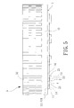
- FIG. 5 shows a side view of the heat dissipating assembly of FIG. 4 .
- FIG. 6 shows a top view of the heat dissipating assembly of FIG. 5 .
- FIG. 7 shows a partial, cross sectional view of the heat dissipating assembly of FIG. 4 according to section line 7 - 7 of FIG. 6 .
- FIG. 8 shows a side view of a heat dissipating assembly of a second embodiment according to the preferred teachings of the present invention.
- FIG. 9 shows an exploded, perspective view of a heat dissipating assembly of a third embodiment according to the preferred teachings of the present invention.
- FIG. 10 shows a partial, enlarged, cross sectional view of the heat dissipating assembly of FIG. 9 .
- FIG. 11 shows an exploded, perspective view of a heat dissipating assembly of a fourth embodiment according to the preferred teachings of the present invention.
- FIG. 12 shows a partial, enlarged, cross sectional view of the heat dissipating assembly of FIG. 11 .
- FIG. 13 shows a partial, enlarged, cross sectional view of the heat dissipating assembly of a fifth embodiment according to the preferred teachings of the present invention.
- FIGS. 4-7 A heat dissipating assembly of a first embodiment according to the preferred teachings of the present invention is shown in FIGS. 4-7 .
- the heat dissipating assembly is utilized with an LED lamp in the illustrated embodiment.
- the heat dissipating assembly can be utilized in other electronic devices requiring heat dissipation according to the teachings of the present invention.
- the heat dissipating assembly of the first embodiment includes a circuit board 1 , a plurality of heat generating elements 2 , a heat dissipating unit 3 , and heat conducting adhesive 4 .
- the circuit board 1 is sandwiched between the heat generating elements 2 and the heat dissipating unit 3 , which are connected by the heat conducting adhesive 4 through welding.
- the circuit board 1 is a printed circuit board (PCB) and preferably an FR-4 or FR-5 board.
- the circuit board 1 includes opposite first and second faces 11 and 12 .
- the circuit board 1 further includes a plurality of through-holes 13 and a plurality of contacts 14 .
- Each through-hole 13 extends from the first face 11 through the second face 12 .
- the through-holes 13 are annularly spaced in this embodiment.
- the contacts 14 are also annularly spaced and adjacent to the through-holes 13 and embedded in the circuit board 1 to provide electrical connection. In this embodiment, each through-hole 13 is located between two contacts 14 .
- each of the heat generating elements 2 is mounted on the first face 11 of the circuit board 1 and is preferably a light emitting diode (LED) and most preferably a white light LED.
- Each heat generating element 2 includes two pins 21 and a heat conducting portion 22 .
- the pins 21 are electrically coupled to the contacts 14 of the circuit board 1 .
- the heat conducting portion 22 of each heat generating element 2 is located at a bottom of the heat generating element 2 and faces one of the through-holes 13 .
- the heat conducting portion 22 of each heat generating element 2 is preferably made of metal material with excellent heat conductivity, such as aluminum, copper, silver, or an alloy thereof.
- Each heat conducting portion 22 has an area larger than that of each through-hole 13 such that each through-hole 13 can be completely covered by the heat conducting portion 22 of one of the heat generating elements 2 .
- the heat generating elements 2 can be any electronic element other than an LED according to the teachings of the present invention.
- the heat dissipating unit 3 is preferably a heat sink and made of metal material with excellent heat conductivity, such as aluminum, copper, silver, or an alloy thereof.
- the heat dissipating unit 3 includes a base 31 and a plurality of fins 32 .
- the base 31 has an engaging face 311 facing one of the first and second faces 11 and 12 of the circuit board 1 .
- the engaging face 311 is in contact with the second face 12 of the circuit board 1 and faces the through-holes 13 .
- the fins 32 are located on the other face of the base 31 opposite to the engaging face 311 .
- An air channel is formed between two fins 32 adjacent to each other. Thus, air can flow through the air channels and come in contact with the fins 32 to proceed with heat exchange, lowering the temperature of the fins 32 .
- the heat conducting adhesive 4 is filled in the through-holes 13 .
- the heat conducting adhesive 4 is preferably of the type having excellent heat conductivity and excellent coupling properties, such as heat-conducting silica gel or metal solder (solder pastes).
- the heat conducting adhesive 4 as the metal solder is heated by surface mount technology (SMT), such as reflow welding, and is melted in each through-hole 13 such that the heat conducting adhesive 4 , after hardening, can be reliably engaged with the engaging face 311 of the base 31 and the heat conducting portion 22 of one of the heat generating elements 2 .
- the heat conducting adhesive 4 as the heat-conducting silica gel may be heated up by high-temperature baking and solidifying process.
- the circuit board 1 is securely sandwiched between the heat generating elements 2 and the heat dissipating unit 3 .
- the temperature of the heat generating elements 2 is increased by the heat generated by themselves.
- the heat is directly transmitted through the heat conducting adhesive 4 to the base 31 of the heat dissipating unit 3 .
- the heat exchange rate is increased by the fins 32 that increase the heat exchange area.
- the heat generating elements 2 can work at an appropriate working temperature, as the temperature of heat generating elements 2 is lowered.
- the performance of the heat generating elements 2 is enhanced, and the service life of the heat generating elements 2 is prolonged.
- the heat generated by the heat generating elements 2 can be directly transmitted through the heat conducting adhesive 4 to the heat dissipating unit 3 .
- the heat conducting adhesive 4 and the heat dissipating unit 3 are made of material with excellent heat conductivity, additional members and/or heat spreader plates are not required. The overall heat dissipating efficiency can be effectively enhanced while reducing the number of members. The manufacturing costs are thus cut.
- the heat-conducting silica gel is preferably chosen as the heat conducting adhesive 4 in the various embodiments for illustration purposes. Since the heat generating elements 2 are directly fixed to the heat dissipating unit 3 by the heat conducting adhesive 4 , a single high-temperature baking and solidifying process is sufficient to complete the assemblage of the circuit board 1 , the heat generating elements 2 , and the heat dissipating unit 3 while securely sandwiching the circuit board 1 between the heat generating elements 2 and the heat dissipating unit 3 .
- the assemblage of the heat dissipating assembly can be accomplished without the need for more processes that are conventionally required to fix the circuit board 1 and the heat generating elements 2 together and to fix the circuit board 1 and the heat dissipating unit 3 together. Further, the heat generating elements 2 and the heat dissipating unit 3 are respectively in contact with the first and second faces 11 and 12 of the circuit board 1 , maintaining reliable assembly. Thus, the assembling process is effectively simplified according to the teachings of the present invention, further enhancing the assembling efficiency.
- FIG. 8 shows a heat dissipating assembly of a second embodiment according to the teachings of the present invention.
- the heat dissipating unit 3 further includes a fan 33 of the axial flow or blower type.
- the fan 33 is rotatably mounted in a recessed portion formed by the fins 32 .
- the fan 33 is rotatable to create air currents flowing away from or towards the base 31 or the fins 32 of the heat dissipating unit 3 , providing active air circulation and further enhancing the heat dissipating efficiency provided to the circuit board 1 and the heat generating elements 2 for the purposes of lowering the temperature.
- FIGS. 9 and 10 show a heat dissipating assembly of a third embodiment according to the teachings of the present invention.
- the circuit board 1 of the third embodiment includes only one through-hole 13 , and two contacts 14 are placed adjacent to the through-hole 13 .
- the through-hole 13 is located in a center of the circuit board 1 and between the two contacts 14 .
- the heat dissipating assembly includes only one heat generating element 2 whose heat conducting portion 22 has a shape corresponding to the through-hole 13 .
- the through-hole 13 is completely covered by the heat conducting portion 22 when the heat generating element 2 is mounted to the first face 11 of the circuit board 1 .
- the fan 33 shown in the second embodiment can be utilized in the third embodiment.
- the heat dissipating assembly according to the teachings of the present invention can easily be assembled regardless of the number of the electronic members and thus can widely be utilized in various electronic devices.
- FIGS. 11 and 12 show a heat dissipating assembly of a fourth embodiment according to the teachings of the present invention.
- the heat dissipating unit 3 further includes a plurality of coupling portions 34 (or only one coupling portion 34 , depending on requirement) formed on the engaging face 311 of the base 31 .
- the coupling portions 34 are arranged in the same way as the through-holes 13 , with each coupling portion 34 corresponding to one through-hole 13 .
- the through-holes 13 are aligned with and link to the coupling portions 34 when the circuit board 1 abuts with the engaging face 311 of the base 31 .
- the coupling portions 34 in the embodiment are implemented as blind holes, but are not limited thereto. Based on this, when the heat conducting adhesive 4 is filled in the through-holes 13 and is baked and solidified with high temperature, the coupling portions 34 may be filled with the heat conducting adhesive 4 .
- the coupling between the base 31 and the heat conducting adhesive 4 may be reinforced by using the coupling portions 34 to increase the coupling area between the base 31 and the heat conducting adhesive 4 .
- FIG. 13 shows a heat dissipating assembly of a fifth embodiment according to the teachings of the present invention.
- the coupling portion 34 includes a plurality of protrusions 341 on an inner wall thereof.
- the protrusions 341 are formed on a bottom of the coupling portion 34 .
- the coupling area between the heat conducting adhesive 4 and the inner wall of the coupling portion 34 may be increased.
- coupling between the heat conducting adhesive 4 and the inner wall of the coupling portion 34 is increased.
Landscapes
- Engineering & Computer Science (AREA)
- General Engineering & Computer Science (AREA)
- Microelectronics & Electronic Packaging (AREA)
- Cooling Or The Like Of Electrical Apparatus (AREA)
- Cooling Or The Like Of Semiconductors Or Solid State Devices (AREA)
Abstract
Description
Claims (26)
Priority Applications (1)
| Application Number | Priority Date | Filing Date | Title |
|---|---|---|---|
| US12/895,952 US8391009B2 (en) | 2010-06-18 | 2010-10-01 | Heat dissipating assembly |
Applications Claiming Priority (2)
| Application Number | Priority Date | Filing Date | Title |
|---|---|---|---|
| US12/818,211 US20110279981A1 (en) | 2010-05-17 | 2010-06-18 | Heat Dissipating Assembly |
| US12/895,952 US8391009B2 (en) | 2010-06-18 | 2010-10-01 | Heat dissipating assembly |
Related Parent Applications (1)
| Application Number | Title | Priority Date | Filing Date |
|---|---|---|---|
| US12/818,211 Continuation-In-Part US20110279981A1 (en) | 2010-05-17 | 2010-06-18 | Heat Dissipating Assembly |
Publications (2)
| Publication Number | Publication Date |
|---|---|
| US20110310559A1 US20110310559A1 (en) | 2011-12-22 |
| US8391009B2 true US8391009B2 (en) | 2013-03-05 |
Family
ID=45328480
Family Applications (1)
| Application Number | Title | Priority Date | Filing Date |
|---|---|---|---|
| US12/895,952 Expired - Fee Related US8391009B2 (en) | 2010-06-18 | 2010-10-01 | Heat dissipating assembly |
Country Status (1)
| Country | Link |
|---|---|
| US (1) | US8391009B2 (en) |
Cited By (5)
| Publication number | Priority date | Publication date | Assignee | Title |
|---|---|---|---|---|
| US20110249406A1 (en) * | 2009-06-20 | 2011-10-13 | LEDAdventures LLC | Heat dissipation system for electrical components |
| US20120106131A1 (en) * | 2010-11-01 | 2012-05-03 | Shenzhen China Star Optoelectronics Technology Co. Ltd. | Heat dissipating structure of light source and backlight module |
| US20130170145A1 (en) * | 2012-01-02 | 2013-07-04 | Tem Products Inc. | Thermal connector |
| US20170153003A1 (en) * | 2015-11-27 | 2017-06-01 | Valeo Vision | Light-emitting device for an automotive vehicle headlamp lighting module and associated lighting module and headlamps |
| CN107731774A (en) * | 2017-09-05 | 2018-02-23 | 横店集团东磁有限公司 | A kind of heat radiating type camera module chip-packaging structure |
Families Citing this family (6)
| Publication number | Priority date | Publication date | Assignee | Title |
|---|---|---|---|---|
| US20110279981A1 (en) * | 2010-05-17 | 2011-11-17 | Alex Horng | Heat Dissipating Assembly |
| US9750126B2 (en) * | 2012-10-22 | 2017-08-29 | Thomson Licensing | Electronic device with combination heat sink/blower or fan assembly having air duct |
| US9433074B2 (en) * | 2013-04-29 | 2016-08-30 | Toyota Motor Engineering & Manufacturing North America, Inc. | Printed wiring boards having thermal management features and thermal management apparatuses comprising the same |
| US10914539B2 (en) * | 2013-05-15 | 2021-02-09 | Osram Sylvania Inc. | Two piece aluminum heat sink |
| US9429370B1 (en) * | 2014-05-27 | 2016-08-30 | Unigen Corporation | Heat sink with flat heat pipe |
| US10028413B2 (en) | 2014-07-25 | 2018-07-17 | Toyota Motor Engineering & Manufacturing North America, Inc. | Heat transfer management apparatuses having a composite lamina |
Citations (15)
| Publication number | Priority date | Publication date | Assignee | Title |
|---|---|---|---|---|
| US6428189B1 (en) * | 2000-03-31 | 2002-08-06 | Relume Corporation | L.E.D. thermal management |
| US20040136163A1 (en) * | 2003-01-14 | 2004-07-15 | Sunonwealth Electric Machine Industry Co., Ltd. | Heat sink device having light-emitting components |
| CN1635824A (en) | 2003-12-31 | 2005-07-06 | 技嘉科技股份有限公司 | Multilayer circuit board with high heat dissipation and manufacturing method thereof |
| US6999318B2 (en) * | 2003-07-28 | 2006-02-14 | Honeywell International Inc. | Heatsinking electronic devices |
| US7054159B2 (en) * | 2000-03-29 | 2006-05-30 | Rohm Co., Ltd. | Printed wiring board having heat radiating means and method of manufacturing the same |
| US20060180821A1 (en) * | 2003-06-30 | 2006-08-17 | Koninklijke Philips Electronics N.V. | Light-emitting diode thermal management system |
| US7549774B2 (en) | 2007-04-24 | 2009-06-23 | Hong Kuan Technology Co., Ltd. | LED lamp with plural radially arranged heat sinks |
| US7572033B2 (en) * | 2007-04-27 | 2009-08-11 | Foxsemicon Integrated Technology, Inc. | Light source module with high heat-dissipation efficiency |
| US7625104B2 (en) | 2007-12-13 | 2009-12-01 | Philips Lumileds Lighting Company, Llc | Light emitting diode for mounting to a heat sink |
| US7682048B2 (en) | 2007-12-21 | 2010-03-23 | Foxsemicon Integrated Technology, Inc. | Lighting emitting diode lamp |
| US7686480B2 (en) * | 2007-04-09 | 2010-03-30 | Coretronic Corporation | Light valve device |
| US7780315B2 (en) * | 2006-05-22 | 2010-08-24 | Valeo Vision | Heat dissipation component and diode lighting and/or signalling device equipped with a component of this type |
| US7929312B2 (en) * | 2007-11-12 | 2011-04-19 | Nec Corporation | Device mounting structure and device mounting method |
| US8062912B2 (en) * | 2008-03-25 | 2011-11-22 | Bridge Semiconductor Corporation | Method of making a semiconductor chip assembly with a post/base heat spreader and horizontal signal routing |
| US8071998B2 (en) * | 2007-12-24 | 2011-12-06 | Kuei-Fang Chen | Light emitting assembly |
-
2010
- 2010-10-01 US US12/895,952 patent/US8391009B2/en not_active Expired - Fee Related
Patent Citations (15)
| Publication number | Priority date | Publication date | Assignee | Title |
|---|---|---|---|---|
| US7054159B2 (en) * | 2000-03-29 | 2006-05-30 | Rohm Co., Ltd. | Printed wiring board having heat radiating means and method of manufacturing the same |
| US6428189B1 (en) * | 2000-03-31 | 2002-08-06 | Relume Corporation | L.E.D. thermal management |
| US20040136163A1 (en) * | 2003-01-14 | 2004-07-15 | Sunonwealth Electric Machine Industry Co., Ltd. | Heat sink device having light-emitting components |
| US20060180821A1 (en) * | 2003-06-30 | 2006-08-17 | Koninklijke Philips Electronics N.V. | Light-emitting diode thermal management system |
| US6999318B2 (en) * | 2003-07-28 | 2006-02-14 | Honeywell International Inc. | Heatsinking electronic devices |
| CN1635824A (en) | 2003-12-31 | 2005-07-06 | 技嘉科技股份有限公司 | Multilayer circuit board with high heat dissipation and manufacturing method thereof |
| US7780315B2 (en) * | 2006-05-22 | 2010-08-24 | Valeo Vision | Heat dissipation component and diode lighting and/or signalling device equipped with a component of this type |
| US7686480B2 (en) * | 2007-04-09 | 2010-03-30 | Coretronic Corporation | Light valve device |
| US7549774B2 (en) | 2007-04-24 | 2009-06-23 | Hong Kuan Technology Co., Ltd. | LED lamp with plural radially arranged heat sinks |
| US7572033B2 (en) * | 2007-04-27 | 2009-08-11 | Foxsemicon Integrated Technology, Inc. | Light source module with high heat-dissipation efficiency |
| US7929312B2 (en) * | 2007-11-12 | 2011-04-19 | Nec Corporation | Device mounting structure and device mounting method |
| US7625104B2 (en) | 2007-12-13 | 2009-12-01 | Philips Lumileds Lighting Company, Llc | Light emitting diode for mounting to a heat sink |
| US7682048B2 (en) | 2007-12-21 | 2010-03-23 | Foxsemicon Integrated Technology, Inc. | Lighting emitting diode lamp |
| US8071998B2 (en) * | 2007-12-24 | 2011-12-06 | Kuei-Fang Chen | Light emitting assembly |
| US8062912B2 (en) * | 2008-03-25 | 2011-11-22 | Bridge Semiconductor Corporation | Method of making a semiconductor chip assembly with a post/base heat spreader and horizontal signal routing |
Cited By (7)
| Publication number | Priority date | Publication date | Assignee | Title |
|---|---|---|---|---|
| US20110249406A1 (en) * | 2009-06-20 | 2011-10-13 | LEDAdventures LLC | Heat dissipation system for electrical components |
| US20120106131A1 (en) * | 2010-11-01 | 2012-05-03 | Shenzhen China Star Optoelectronics Technology Co. Ltd. | Heat dissipating structure of light source and backlight module |
| US20130170145A1 (en) * | 2012-01-02 | 2013-07-04 | Tem Products Inc. | Thermal connector |
| US8929077B2 (en) * | 2012-01-02 | 2015-01-06 | Tem Products Inc. | Thermal connector |
| US20170153003A1 (en) * | 2015-11-27 | 2017-06-01 | Valeo Vision | Light-emitting device for an automotive vehicle headlamp lighting module and associated lighting module and headlamps |
| US10281130B2 (en) * | 2015-11-27 | 2019-05-07 | Valeo Vision | Light-emitting device for an automotive vehicle headlamp lighting module and associated lighting module and headlamps |
| CN107731774A (en) * | 2017-09-05 | 2018-02-23 | 横店集团东磁有限公司 | A kind of heat radiating type camera module chip-packaging structure |
Also Published As
| Publication number | Publication date |
|---|---|
| US20110310559A1 (en) | 2011-12-22 |
Similar Documents
| Publication | Publication Date | Title |
|---|---|---|
| US8391009B2 (en) | Heat dissipating assembly | |
| US8279607B2 (en) | Cooling module assembly method | |
| CN110459512B (en) | Cooling motherboard and optical module | |
| JP5453187B2 (en) | Backlight unit | |
| CN101776248B (en) | Lamps and lighting devices | |
| US20110279981A1 (en) | Heat Dissipating Assembly | |
| CN101539279B (en) | LED Module | |
| JP2008258264A (en) | Light emitting diode module structure for light source unit | |
| US7724528B2 (en) | Thermal dissipation heat slug sandwich | |
| CN101994929A (en) | Light emitting module | |
| CN201093439Y (en) | LED heat dissipation substrate | |
| EP2388812A2 (en) | Heat dissipating assembly | |
| JP2006066725A (en) | Semiconductor device having heat dissipation structure and method of assembling the same | |
| CN213210958U (en) | High-efficient radiating radiator | |
| CN102129820B (en) | Light-emitting diode devices and displays | |
| CN102454956A (en) | Single LED (light-emitting diode) light source radiating seat and LED lamp | |
| CN102263066B (en) | Combination structure of heat dissipation module | |
| CN214154942U (en) | Circuit board assembly | |
| JP5200076B2 (en) | Combination structure of heat dissipation module | |
| CN108925027B (en) | Heat radiation structure | |
| US20140168979A1 (en) | Light emitting diode module with heat-conducting poles | |
| CN201788961U (en) | Combination structure of heat dissipation module | |
| TWI911937B (en) | Thermal conductive block and combination of heat dissipation device and printed circuit board assembly | |
| TW201106510A (en) | Light emitting module | |
| CN119836074B (en) | Thermoelectric separation LED module and manufacturing method thereof |
Legal Events
| Date | Code | Title | Description |
|---|---|---|---|
| AS | Assignment |
Owner name: SUNONWEALTH ELECTRIC MACHINE INDUSTRY CO., LTD., T Free format text: ASSIGNMENT OF ASSIGNORS INTEREST;ASSIGNORS:HORNG, ALEX;KUO, CHI-HUNG;CHUNG, CHIH-HAO;REEL/FRAME:025076/0338 Effective date: 20100827 |
|
| STCF | Information on status: patent grant |
Free format text: PATENTED CASE |
|
| FPAY | Fee payment |
Year of fee payment: 4 |
|
| AS | Assignment |
Owner name: SUNONWEALTH ELECTRIC MACHINE INDUSTRY CO., LTD., TAIWAN Free format text: CHANGE OF ASSIGNEE ADDRESS;ASSIGNOR:SUNONWEALTH ELECTRIC MACHINE INDUSTRY CO., LTD.;REEL/FRAME:052815/0567 Effective date: 20200602 |
|
| MAFP | Maintenance fee payment |
Free format text: PAYMENT OF MAINTENANCE FEE, 8TH YEAR, LARGE ENTITY (ORIGINAL EVENT CODE: M1552); ENTITY STATUS OF PATENT OWNER: LARGE ENTITY Year of fee payment: 8 |
|
| FEPP | Fee payment procedure |
Free format text: MAINTENANCE FEE REMINDER MAILED (ORIGINAL EVENT CODE: REM.); ENTITY STATUS OF PATENT OWNER: LARGE ENTITY |
|
| LAPS | Lapse for failure to pay maintenance fees |
Free format text: PATENT EXPIRED FOR FAILURE TO PAY MAINTENANCE FEES (ORIGINAL EVENT CODE: EXP.); ENTITY STATUS OF PATENT OWNER: LARGE ENTITY |
|
| STCH | Information on status: patent discontinuation |
Free format text: PATENT EXPIRED DUE TO NONPAYMENT OF MAINTENANCE FEES UNDER 37 CFR 1.362 |
|
| FP | Lapsed due to failure to pay maintenance fee |
Effective date: 20250305 |