US838136A - Combined telephone and district messenger system. - Google Patents
Combined telephone and district messenger system. Download PDFInfo
- Publication number
- US838136A US838136A US13285602A US1902132856A US838136A US 838136 A US838136 A US 838136A US 13285602 A US13285602 A US 13285602A US 1902132856 A US1902132856 A US 1902132856A US 838136 A US838136 A US 838136A
- Authority
- US
- United States
- Prior art keywords
- signal
- box
- call
- telephone
- line
- Prior art date
- Legal status (The legal status is an assumption and is not a legal conclusion. Google has not performed a legal analysis and makes no representation as to the accuracy of the status listed.)
- Expired - Lifetime
Links
Images

Classifications
-
- H—ELECTRICITY
- H04—ELECTRIC COMMUNICATION TECHNIQUE
- H04L—TRANSMISSION OF DIGITAL INFORMATION, e.g. TELEGRAPHIC COMMUNICATION
- H04L12/00—Data switching networks
- H04L12/28—Data switching networks characterised by path configuration, e.g. LAN [Local Area Networks] or WAN [Wide Area Networks]
-
- H—ELECTRICITY
- H04—ELECTRIC COMMUNICATION TECHNIQUE
- H04L—TRANSMISSION OF DIGITAL INFORMATION, e.g. TELEGRAPHIC COMMUNICATION
- H04L12/00—Data switching networks
- H04L12/28—Data switching networks characterised by path configuration, e.g. LAN [Local Area Networks] or WAN [Wide Area Networks]
- H04L12/2803—Home automation networks
- H04L2012/284—Home automation networks characterised by the type of medium used
- H04L2012/2845—Telephone line
Definitions
- My invention contemplates a combined telephone and messenger-service system in which each subscriber is provided with means-such, for example, as a call-box-for transmitting a signal to the switchboard operator at the central station. 'This signal can be employed for different purposes.
- the call-box when operated may transmit a signal of such character as to indicate to the central operator that the subscriber desires a messengerboy.
- Other uses are obvious, however, and for this reason I do not/limit my invention to any particular use or purpose. 1
- my invention contemplates the provision of signal-transmitting mechanism which is independent of and telephone apof transmitting a signal of a distinct and pre determined character. to the switchboard operator at the telephone-exchange-station.
- FIG. 1 is a diagram .of a subscribers line-circuit equip ed with a signaling mechanism, wlnch is in the form of a callbox bridged across the Fig. 2 is an enlarged front elevation of the signal-transmitting mechanism or call-box shown in Fig. 3 is a front elevation of the same with the front plate or cover removed. Fi 4 is a side elevation of the saidcall-box wit the casing broken away.
- my improved.combined telephone and signaling system may comprise a subscribers telephone A of any suitable known or approved construction.
- the switchboard apparatus at the central station able known or approved construction.
- the said jack mayconsist of the sleeve contaet b and the tip-spring b.
- the operators connecting-plugC may have the tip and sleeve contacts a and c ada tedto register with the said contacts]; and 6
- the line-signal or signal by which the subscriber attracts the attention of the switchboard operator may consist of a' line-relay D,
- ac oss the line and connectedin series with thc'battery (1.
- One end of this bridge can be permanently secured to the line conductor secured to the contact or anvil d, upon which latter the spring I): normally rests. can be provi ed with an armature (1 a apted to close a local-batte circuit through the line-lamp d.
- the current both for signaling and talking purposes; is supplied from a central source, and when the subscriber wishes connection with some other line he removes hook-switch of the telephone set at A, so as to close the line-circuit and cause the lamp (1 toglo-w as a'result The oper-' but it of any suita le'or approved construction. however, the plug ,0, whichmay be the calling-plug of the cord-circuit, is connected to ground' through a test-battery E.
- the signal-transmitting mechanism F may beef any suitable character, its purpose be ing to provide means independent of the sub- 1, and the other end can be understood that this may be scribers telephone m ho k switch whereby. a distinctive-signal may be-transmitted overthe telephone-line to the switchboard opera 'at or at the central station?
- this signal-transmitting,mechanism may be in the form of the usual and well-known callbox employed in district-messenger systems.
- thebox may be bridged across the subscribers line, as shown in Fig. 1, pro' I viding the telephone system is of thecomplete metallic type, such as shown. With this pro vision the subscriber when a 1nessen- ,ger isdesired can rotate the crank or handle;
- the make-andbreak device within the call-box may be of the ordinary orwell-known type.
- call-box herein-- 2, 3, and 4 I have'illustr'ated the usual and well-known form of call-box.
- the make and-break mechanism .in this box involves the rotary disk f T and the spring contact-finger f These two deyic'es, the disk and the contact-finger, are, it will be readily understood, connected, respectively, with"wires'4 and 5, bridged across the wires. '1 and 2, and
- This target or s uttercan be pivoted at g and can beprovided witha ping and also with the ejections g
- the signal-receiving device in the call-box is automatically set and is then not released until the central operator touches the jack with the tip of the plug.
- both the signal-transmitting mechanism and the signal-receiving mechanism are distinct from and independent of the telephone hook-switch and bell.
- these additional signal transmitting and receiving devices are independent of and in no way related to the devices usually involved in a subscribers telephone set for sending and receiving calls.
- My improved signal-transmitting arrangement is ada ted to o erate in conjunction withany 0 the usua signal-receiving devices which may be found on a switchboard at thecentral station.
- My improved signalreceiving devices are ada )ted to operatc'in conjunction with any of t 1e signal-transmitting instrulnentalities or agencies which may be found on a telephone-switchboard.
- the usual and well-known busytest may be employed, as explained, for o crating the signal-receiving devices in t is call-box.
- What I claim as my invention is- 1.
- a subscriber's telephone set suitable-switchboard ap aratus, a suitable line connection between t 1e switchboard apparatus and the telephone set, a call-box associated With the subsciibers telephone set and connected With the line,
- said call-box involving a signal-receiving device located in a conducting-path extending from one side of the line to ground, whereby the central operator may employ the usual busy-test for operating said signal, said box being normally in condition to revent the passage therethrough of any of t 1e currents employed in telephoning.
- a telephone system involving, at the, subscribers station, a telephone set, and, at-the central station, line-signal apparatus, and a grounded busy-test apparatus; combined with a si nal-transmit'terkhaving circuit-controlling (Ievices arranged to actuate the linesignal, and a grounded signal-receiving device, arranged to be automatically operated through a grounded circuit when'the busytest apparatus is associated with the line in the usual manner by the central operator.
- si nal-transmit'terkhaving circuit-controlling Ievices arranged to actuate the linesignal, and a grounded signal-receiving device, arranged to be automatically operated through a grounded circuit when'the busytest apparatus is associated with the line in the usual manner by the central operator.
Landscapes
- Engineering & Computer Science (AREA)
- Computer Networks & Wireless Communication (AREA)
- Signal Processing (AREA)
- Structure Of Telephone Exchanges (AREA)
Description
PATENTED DEC. 11, 1906.
No. 888,136. f
V J; G. NOLEN.) COMBINED TELEPHENE AND DISTRICT MESSENGER SYSTEM.
APPLICATION rum-Nov. 2e. 1902. v
2' SHEETS-SHEET 1.
' -N0- 838,136. PATENTED DEC. 11, 1906.
I v J. G. NOLBNQ GOMBINEDSTBLBPHONE AND DISTRICT MESSENGER SYSTEM.
APPLICATION FILED NOV.26,1902.
2 SHEETSSHBET 2.
fully appear.
- line at the subscribers station.
" 1. Fig.
UNITED STAT 1s PATENT OFFICE.
(JAMES c. NOLEN, or cuicaco. ILLINOIS, ASSIGNORI FRANK B. COOK,
or ONE-HALF TO OF CHICAGO, ILLINOIS.
COMBINED TELEPHONE AND DISTRICT MESSENGER SYSTEM.
Be it'known that-I, JAMES G. NoLnN, a citizen of the United States of America, and a resident of Chicago, Cook county, Illinois, ha veinvent'ed a certain new and useful Improvement in a Combined Telephone and District Messenger System, of which the following is a specification.
My invention contemplates a combined telephone and messenger-service system in which each subscriber is provided with means-such, for example, as a call-box-for transmitting a signal to the switchboard operator at the central station. 'This signal can be employed for different purposes. For example, the call-box when operated may transmit a signal of such character as to indicate to the central operator that the subscriber desires a messengerboy. Other uses are obvious, however, and for this reason I do not/limit my invention to any particular use or purpose. 1
' Broadly-considered, "my invention contemplates the provision of signal-transmitting mechanism which is independent of and telephone apof transmitting a signal of a distinct and pre determined character. to the switchboard operator at the telephone-exchange-station.
.The nature and operation of my invention will, however, more fully appear.
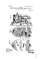
As a matter of further and special improvement my invention further contemplates the provision of means whereby the switchboard operator may, through the medium of the telephone-circuit and the call-box, answer the signal transmitted from the call-- box to the central exchange and may in-this' 40 way notify the subscriber that the call for a- 'messen er has been observed. This feature of niy mvention will also hereinaftermore In the accompanying drawings, Figure I is a diagram .of a subscribers line-circuit equip ed with a signaling mechanism, wlnch is in the form of a callbox bridged across the Fig. 2 is an enlarged front elevation of the signal-transmitting mechanism or call-box shown in Fig. 3 is a front elevation of the same with the front plate or cover removed. Fi 4 is a side elevation of the saidcall-box wit the casing broken away.
Specification of Letters Patent. Application filed Nove nher 26, 1902 Serial No. 132.856.
The said rela the receiver .from the of theenergizing of the relay D. ators' cord-circuit is not described f-fwill be readil Prefers bly,
Patented Dec. 11, 1906.
Referring to Fig. 1, my improved.combined telephone and signaling system may comprise a subscribers telephone A of any suitable known or approved construction.
Fromthis telephone two conductors 1 and 2 lead to the spring-jack B on the switchboard at the central station. Thus it will be seen that the system is of the complete metalliccireuit type. The switchboard apparatus at the central station able known or approved construction. For example, the said jack mayconsist of the sleeve contaet b and the tip-spring b. The operators connecting-plugC may have the tip and sleeve contacts a and c ada tedto register with the said contacts]; and 6 The line-signal or signal by which the subscriber attracts the attention of the switchboard operator may consist of a' line-relay D,
can also be of any suitbridged ac oss the line and connectedin series with thc'battery (1. One end of this bridge can be permanently secured to the line conductor secured to the contact or anvil d, upon which latter the spring I): normally rests. can be provi ed with an armature (1 a apted to close a local-batte circuit through the line-lamp d. With this arrangement the current, both for signaling and talking purposes; is supplied from a central source, and when the subscriber wishes connection with some other line he removes hook-switch of the telephone set at A, so as to close the line-circuit and cause the lamp (1 toglo-w as a'result The oper-' but it of any suita le'or approved construction. however, the plug ,0, whichmay be the calling-plug of the cord-circuit, is connected to ground' through a test-battery E.
This of course is with'respect. to the usual well-known use of multiple switchboards, in
which it is desirable that each operator be provided with means whereby a busy test may be made by simply touchingth'e plugtip to the test-ring of the. jack connected with the line called for. These, however, are matters well understood by those'skilled inthe art.
The signal-transmitting mechanism F may beef any suitable character, its purpose be ing to provide means independent of the sub- 1, and the other end can be understood that this may be scribers telephone m ho k switch whereby. a distinctive-signal may be-transmitted overthe telephone-line to the switchboard opera 'at or at the central station? For example, this signal-transmitting,mechanism may be in the form of the usual and well-known callbox employed in district-messenger systems.
-- Insuch case thebox may be bridged across the subscribers line, as shown in Fig. 1, pro' I viding the telephone system is of thecomplete metallic type, such as shown. With this pro vision the subscriber when a 1nessen- ,ger isdesired can rotate the crank or handle;
f of thec'all-box in theusual manner, and
i 5 this crank ,lor handle while. returning toits' I ormal position will then open and close the line-circuit, andthe'reby cause an interinitl tent flashing or glowing of the I tention of the switchboard operator, who, oba 5 serving the p6C'l1ll&1 'Cl1tT2LOi/61 of the signal and recognizing this signal asmeaning that,
't'he 'subsc'riber desires a messen er, then ,touches the tip of the plug Cto the ,s eeve b of- ,the jack, so'as to complete a groundcircuit 0 "from the battery E th'rough one side of the line to the call-box, thence't'o. the ground through the answering, mechanism of the call-box, and 'back through earth to thesaid battery. The-closi'n of this grounded linei 5 circuit causes a signal to be dis 'layed on the front of the call-box advising t e subscriber that the central operator'has' understood the .signal'and has'given' the order for a messenger.
so as not only to su'bserve itsnatural function of transmitting telephonemessage'sfrom one subscriber to another, but so as also to 4 5 enable each subscriber to turn in a call for a messenger without doing anytelepho'ning.
.Prior to my invention it has of course been the custom to turn 1n a call fora messenger to the central telephone exchange' by taking 50,; down thereceiy'er' and e rplaining what is wanted to. the central operator; but with my improved arrangement this is no longer nec essary, and the subscriber'can now give the switchboard operator an order for messenger 5'5 -by simply operating a crank or handle, and, furthermore, the order is given in this sun-- plified manner without leaving the subscriber uncertain as to whether or not the order has been received and acted upon. oo-
shown may be of any suitable or approved character. In other words, the make-andbreak device within the call-box may be of the ordinary orwell-known type. In Figs.
is due to the operation: of the;
Thus it will be seen that by my im- 40 proved arrangement the ordinary telehone system may be easily and quickly mo ified,
be located The construction of the call-box herein-- 2, 3, and 4 I have'illustr'ated the usual and well-known form of call-box. The make and-break mechanism .in this box involves the rotary disk f T and the spring contact-finger f These two deyic'es, the disk and the contact-finger, are, it will be readily understood, connected, respectively, with"wires'4 and 5, bridged across the wires. '1 and 2, and
the notches in the peripherv of the disk cause the make-and-break action whenthe diskis revolved and returned to its norm by the action of the spring f As'is well known,.th' spring is wound up by the rotation of' the handle or crankf and in unwind ing then slowly rotates the said diskthrough j the medium of the gearing f As to the means in the eaILbo by'Wliich the subscribers call is answered, it willfqbe understood that any suitable devicesor instruments can be 'employed. For example, the'front of the nor; may be cut away, so as $5 normally to ex fo'se "the target orshutter G. This target or s uttercan be pivoted at g and can beprovided witha ping and also with the ejections g The crank-shaft, ;upon 1 whic the crank f inounted-,ca'n be PI'O'. yided with. an -arm"g carrying a springpressed -pawlor'hook g Normally this hook engages-the projections 9 Therefore I when the crank is rotated in a clockwise di-. rection the hook causes the target to rotate 5 upon this pivot until the pin 9 engages the latch 9 This latch, it will be seen, is in the form ofan arm mounted on the armature g of the relay 'or electromagnet 9, connected between wire 4 and the ground 3, as by wire I00 6.- With'this arrangement the crank-shaft after being rotated can return to its normal position, leaving the target held away from the opening in the front of the box by the latch The relay or electromagnet if may 10 5 in a conducting-path extending from the. sleeve side of the line to ground, as
indicated at 3. Thus when the target or shaft hasbeen set and after the make-andbreak device has run down and transmitted 1 10 the signal over the line to'the switchboard operator the latter can then close a grounded circuit from the battery E through the magnet g by simply touchin the .tip' of the plug 0 to the test ng 'ringzof t 1e jack B. course energizes the" relay or electromagnet g, causing it tdattract this armature and in this wa releasing'the target or shutter. The latter t en returns to its normal or displayed position behind the opening in the'call-box izo casing, thereby letting the subscriber know that the order for a messenger has been re ceived and understood. Thus it may be. seenthat myinventio'n' not only contem plates a simple way of modifying a .tele- 1'25 phone system, so.as to combine 'a telephone service with a district messenger service, but also a special form of call-box, whereby the al position 5 a latter may be employed as a signal-receiving device as well as a signal-transmitting means.
When the call-box is pulled, the signal-receiving device in the call-box is automatically set and is then not released until the central operator touches the jack with the tip of the plug. Thus both the signal-transmitting mechanism and the signal-receiving mechanism are distinct from and independent of the telephone hook-switch and bell.
. In other words, these additional signal transmitting and receiving devices are independent of and in no way related to the devices usually involved in a subscribers telephone set for sending and receiving calls.
My improved signal-transmitting arrangement is ada ted to o erate in conjunction withany 0 the usua signal-receiving devices which may be found on a switchboard at thecentral station. My improved signalreceiving devices are ada )ted to operatc'in conjunction with any of t 1e signal-transmitting instrulnentalities or agencies which may be found on a telephone-switchboard. For
example, the usual and well-known busytest may be employed, as explained, for o crating the signal-receiving devices in t is call-box.
What I claim as my invention is- 1. The combination of a subscriber's telephone set, suitable-switchboard ap aratus, a suitable line connection between t 1e switchboard apparatus and the telephone set, a call-box associated With the subsciibers telephone set and connected With the line,
said call-box involving a signal-receiving device located in a conducting-path extending from one side of the line to ground, whereby the central operator may employ the usual busy-test for operating said signal, said box being normally in condition to revent the passage therethrough of any of t 1e currents employed in telephoning.
2. The combination of a switchboard apparatus involving a plug connected through currents employed in telephoning.
battery-to ground, and involving also a jack with a testing-ring, a subscribers tele hone set, a signal-receiving device connecte with the line and associated with said telephone set, said signal-receiving device being lo-v catcd in a conducting-path extending between one side of the line and ground, whereby the said signal-receiving device may be caused to give a signal by touching the tip of said plug to the testing-ring of said jack, but said signahreceiving device being normally in condition to prevent the passage therethrough of any of the currents employed in telephoning.
3. The combination of the subscribers telephone set, suitable switchboard apparatus, suitable line coimection between the switchboard apparatus and the telephone set, the call-box associated with the telephone set and connected with the line, said call-box involving a signal-receivin device adapted to be automatically set w en the call-box is pulled, and adapted to be released by means located at the central station, but said box being normally in condition to prevent the passage therethrough of any of the 4. In a system of the c iaracter described, a telephone system involving, at the, subscribers station, a telephone set, and, at-the central station, line-signal apparatus, and a grounded busy-test apparatus; combined with a si nal-transmit'terkhaving circuit-controlling (Ievices arranged to actuate the linesignal, and a grounded signal-receiving device, arranged to be automatically operated through a grounded circuit when'the busytest apparatus is associated with the line in the usual manner by the central operator.
Signed by me, at Chicago, Cook-county, Illinois, this 21st day of November, 1902.
JAMES G. NOLEN.
Witnesses: WM. A. HARDERS,
HARRY P.-BAUMGARTNER.
Priority Applications (1)
| Application Number | Priority Date | Filing Date | Title |
|---|---|---|---|
| US13285602A US838136A (en) | 1902-11-26 | 1902-11-26 | Combined telephone and district messenger system. |
Applications Claiming Priority (1)
| Application Number | Priority Date | Filing Date | Title |
|---|---|---|---|
| US13285602A US838136A (en) | 1902-11-26 | 1902-11-26 | Combined telephone and district messenger system. |
Publications (1)
| Publication Number | Publication Date |
|---|---|
| US838136A true US838136A (en) | 1906-12-11 |
Family
ID=2906610
Family Applications (1)
| Application Number | Title | Priority Date | Filing Date |
|---|---|---|---|
| US13285602A Expired - Lifetime US838136A (en) | 1902-11-26 | 1902-11-26 | Combined telephone and district messenger system. |
Country Status (1)
| Country | Link |
|---|---|
| US (1) | US838136A (en) |
-
1902
- 1902-11-26 US US13285602A patent/US838136A/en not_active Expired - Lifetime
Similar Documents
| Publication | Publication Date | Title |
|---|---|---|
| US838136A (en) | Combined telephone and district messenger system. | |
| US967113A (en) | Combined telephone and alarm or kindred service system. | |
| US2252629A (en) | Supervisory signal system | |
| USRE12056E (en) | yurgae | |
| US750270A (en) | Electric signaling apparatus | |
| US1831901A (en) | Telephone system | |
| US800534A (en) | Secret-service system for interconnecting telephone-lines. | |
| US690289A (en) | Telephone-meter. | |
| US840718A (en) | Visual recorder for telephone systems. | |
| US1856714A (en) | Printing telegraph radial switching system | |
| US741282A (en) | Telephone system. | |
| US465989A (en) | chase | |
| US401334A (en) | Patrick b | |
| US335708A (en) | Automatic telephone-exchange system | |
| US825625A (en) | Combined telephone and alarm system. | |
| US367219A (en) | System of telephonic intercommunication | |
| US1109616A (en) | Electrical signaling system for telephone-exchanges. | |
| US234578A (en) | d lnfreville | |
| US984211A (en) | Electrical alarm system. | |
| US810335A (en) | Telephone party-line system. | |
| US669832A (en) | Combined telephone and fire-alarm apparatus. | |
| US251955A (en) | sceibner | |
| US424635A (en) | Electric call | |
| USRE12383E (en) | Telephone selective system | |
| US378679A (en) | Lock-out box and shunt-circuit for telephone-exchanges |