US1856714A - Printing telegraph radial switching system - Google Patents
Printing telegraph radial switching system Download PDFInfo
- Publication number
- US1856714A US1856714A US474994A US47499430A US1856714A US 1856714 A US1856714 A US 1856714A US 474994 A US474994 A US 474994A US 47499430 A US47499430 A US 47499430A US 1856714 A US1856714 A US 1856714A
- Authority
- US
- United States
- Prior art keywords
- relay
- receiving
- division
- telegraph
- contact
- Prior art date
- Legal status (The legal status is an assumption and is not a legal conclusion. Google has not performed a legal analysis and makes no representation as to the accuracy of the status listed.)
- Expired - Lifetime
Links
- 238000004804 winding Methods 0.000 description 29
- 230000003750 conditioning effect Effects 0.000 description 4
- 238000010586 diagram Methods 0.000 description 3
- 239000002184 metal Substances 0.000 description 3
- 230000005540 biological transmission Effects 0.000 description 2
- 230000008054 signal transmission Effects 0.000 description 2
- 230000000007 visual effect Effects 0.000 description 2
- 235000017276 Salvia Nutrition 0.000 description 1
- 241001072909 Salvia Species 0.000 description 1
- 238000012986 modification Methods 0.000 description 1
- 230000004048 modification Effects 0.000 description 1
- 235000020030 perry Nutrition 0.000 description 1
Images

Classifications
-
- H—ELECTRICITY
- H04—ELECTRIC COMMUNICATION TECHNIQUE
- H04L—TRANSMISSION OF DIGITAL INFORMATION, e.g. TELEGRAPHIC COMMUNICATION
- H04L12/00—Data switching networks
- H04L12/02—Details
- H04L12/16—Arrangements for providing special services to substations
- H04L12/18—Arrangements for providing special services to substations for broadcast or conference, e.g. multicast
Definitions
- Y., A CORPORATION Ol' NEW YORK PRINTING TELEGRAPH RADIAL BWITCHING SYSTEM rlhis invention relates to printing telegraph switching systems and more particularly to a system which has a central station plurality of other stations.
- a primary object of. this invention is to ⁇ produce a printing telegraph typewriter system whereby an instrument at one of several switchboards may send a message which will be received and recorded in typewritten form on a selected few or on all machines connected to the system.
- Another object is to provide means for controlling the apparatus at all switchboards in the system from a remote central switchboard and for visually indicating to the operator at the central switchboard the proper functioning of the apparatus at each otice.
- a feature of this invention is a special rotary switch circuit arrangement located at each otlice for conditioning the apparatus to automatically rebroadcast messages to a group of stations.
- a further feature is the use of circuit means'whereby the central switchboard may obtain control of each local switchboard.
- the switching system to be dcscribed comprises a central switchboardconnected to several distant local switchboards. Each of these. in turn, is connected through branch circuits with the various local receiving stations of which it forms the central point.
- Chat channels are utilized to connect the central switchboard with all the local switchboards. These channels may be used singly or simultaneously and over them it is possible to carry on a two-way simultaneous (duplex) service.
- system of this type is especially adapted tor use in police Work and in business concerns where it is necessary quickly to send information to many distant localities simultaneously.
- the operator at the machine simply types the message on a keyboard similar to that of a standard typewriter and what is typed is automatically recorded on vthe receiving machines. -In this manner a permanent record is made by both the transmitting and receiving machines.
- FIG. l shows diagrammatically, the general arrangement of a radial printin telegraph system embodying the features o this invention
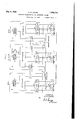
- Fig. 2 shows in detail the circuit diagram of the central switchboard or general headquarters of the system
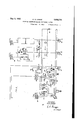
- Fig. 3 shows in detail the circuit diagram of the local or division headquarters.
- the telegraph system shown in F ig. 1 cornprises a central or general headquarters station A and two division stations B and C. Each station is equipped with a switchboard ⁇ 1 having, normally associated therewith a.
- a one-way polar repeating station 4 is provided for each telegraph line 3.
- Two-way telegraph channels 8 connect each division station with the central station A. These channels may be either full duplex or two one-way channels over which two-way simultaneous servicemay be carried on.
- a receiving set 9 individual to each telegraph channel 8 is provided. Repeaters may be inserted in these channels if desired. The repeaters may be full duplex, one-way or any of the repeaters commonly used and well known in the telegraph art for two-Way simultaneous communication.
- the repeater 4 may be located at the switchboard or at a special repeater board located near the station.
- a special remote control code or selector key 7 is provided for transmitting a series of code impulses for conditioningthe apparatus at each division station for automatically rebroadcasting mes'- with each division.
- Several receiving sets 6 may be arranged in series with any particular telegraph line 3.
- selector key 7 at general headquarters will actuate the relay equipment at all the. division headquarters to which the central station desires to broadcast. This relay equipment will retransmit the incoming signals to all the receiving sets connected tothe switchboard of which it forms the central point.
- general headquarters may broadcast the signals to the receiving sets connected to its own station if it so desires.
- the switchboard at station A is so arranged that by means of keys it may transmit to a selected few or all division stations connected to the system. It general headquarters wishes to communicate with any or all division headquarters without broadcasting to the receiving stations associated with the respective division switchboards this may be done by transmitting from general headquarters without operating code selector key 7.
- receiving sets 9 are provided at the central switchboard A and at the respective division switchboards for connection in each telegraph channel 8 associated In broadcasting from central station A each of the sets 9 located at A is actuated by the proper functioning of the apparatus at the respective division station to which the set is connected by its respective telegraph channel 8. In this manner, headquarters is provided with a visual typewritten record of the message being broadcast and automatically retransmitted back over the telegraph channel 8 as an indication of the proper functioning of the apparatus at each oiice. l
- Fig. 2 Broadcasting from general headquarters Fig. 2 taken together with Fig. 3 and placed to the left of Fig. 3 shows a schematic circuit of the general headquarters station equipment as well as that of a division station equipment. In connection with these figures, the circuit operation will irst be considered for broadcasting a message from general headquarters (Fig. 2) to one or more division stations (Fig. 3). Only two telegraph channels and two receiving stations are shown connected to the central switchboard.
- code selector key 7 will be operated.
- the operation of code key 7 through one revolution will transmit a series of tive special break and make signals by causing spring 11 of the key to make and break contact with the metal of the key thus opening and closing the operating path for relay 12.
- Relay 12 is a special master relay with two windings and is normally held operated to its marking position on a circuit from battery through the upper winding of relay 12 to ground through the sending and receiving printer 13 and the contact of code key 7 Current through the lower or biasing winding tends to operate relay 12 against its spacing contact. The strength of the current flowing through the upper winding is greater than the biasing current and holds the armature of relay 12 to its marking contact.
- the transmission of an open or break signal from printer 13 or code key 7 will open the operating circuit through vthe upper winding and cause. the armature of relay 12 to move to its spacing contact.
- sending relays 14, 15, 16 and 17 have their operating windings connected in series in a circuit having one end connected to the spacing contact and the other end connected to the marking contact of the master relay 12, as shown.
- Resistances 40 and 41 connect the marking and spacing contacts, respectively, of. relay 12 to battery 18.
- the armature of relay 12 is grounded.
- the armature ot relay 12 As the armature ot relay 12 operates in accordance with signals transmitted from printer 13 or from code selector key 7, it causes the spacing and marking contacts of relay 12 to be grounded alternately. With the armature thereof on the spacing contact, current Hows from battery 18 through resistance 40 through the windings of all the sending relays in series and thence to ground through the spacing contact and armature of relay 12. All the sending relays 14, 15, 16 and 17 are then operated against their respective spacing contacts. When the armature of relay 12 moves to its marking contact, the direction of current flow through the windings of the sending relay is reversed, flowing now through resistance 41 and through the windings of the sending relays in series ,to ground through the marking contact and armature of relay 12. The sending relays are thus operated against their respective marking contacts. In this way all the sending relays are caused to follow signals transmitted from printer 13, simultaneously. Any number of sending relays may be inserted in the circuit with their windings in series to transmit signals to any desired number of division stations or brancll receiving stations
- repeaters D and D lay 12 will open and close a circuit traced from positive battery 43 through the winding of relay 20, contacts of relay 14, through one side of telegraph channel 18 through the receiving printer 48, one Winding of relay 46, break contact of relay 50 to ground 47 at the division headquarters (Fig. 3), thus operating the receiving printer and causin the armature of relay 46 to move to its mar in position.
- the operation of relay 46 (F1g. 3) will actuate relay equipment at the division switchboard connected to channel 18 and cause signals to be automatically transmitted back over the line to operate receiving print-v er 26. This will be described in connection with Fig. 3. As mentioned previously, full duplex, one-way and other repeaters may be inserted into the telegraph channel it considered desirable.
- Relay 20 in releasing, will light lamp 22 as an indication to the operator at the switchboard that signals are being sent to the division station connected to telegraph channel 18.
- Key 24 is provided for short-circuiting the contacts of sending relay 14 to prevent the signals from being transmitted over channel 18. In this manner the central switchboard may broadcast to a selected few of the division stations or to all the divisions as desired.
- the operator at gen eral headquarters by watching the lamp indicators or the position of keys 24 and 25, can quickly observe which division stations are connected to receive the broadcast signals.
- the operation of the receiving set 26 is a visual indication to the central switchboard that the apparatus at the division station to which the set is connected is functioning properly.
- Receiving set 26 is also used to receive signals transmitted from the division switchboard. This will be described in connection with the transmission of signals from a. division station.
- Telephone channel 19 connects another division switchboard to the central switchboard.
- Lamp indicator 23 and receiving set 27 associated with sending relay 15 and telegraph channel 19 are provided to function in a manner similar to that described for lamp indicator 22 and receiving set 26 associated with sending relay 14.
- Short-circuiting key and relay 21 are connected in the circuit in a manner similar to that described for short-circuiting key'24 and relay 20 and serve a similar purpose.
- Relay 35 has two windings, through one of which a biasing current flows. This biasing current normally tends to keep the armature against the left Contact. The low of current through the lett winding operates relay 35 and causes its armature to move to the right. The alternate movement of the armature of relay 35 will transmit current tirst of one polarity and then of the otherl polarity to operate receiving set 31 over telegraph line 33.
- Filter 39 is a noise killer and servesto reduce undesirable interference in other telegraph wires.
- receiving set 32 will receive the transmitted message through oneway polar repeater D ⁇ identical with D) and upon operation of key 38.
- the operator at the central switchboard may transmit to one or all divisions, and to one or all the receiving sets connected to general headquarters by operatingthe proper keys. This is quite different from the division switchboard which will now be described.
- code key 7 will cause spring 11 to momentarily break contact w-ith the metal wheel of'key 7 which, in turn, will cause the operation of relay 12 and sending relays 14, 15, 16 and 17 to their respective spacing contacts.
- the operation of relay 14 to its spacing contact ⁇ will open the operating path through the right-hand Winding of relay 46 which will now move to its spacing contact.
- the movement of the armature of relay 46 to its spacing Contact will complete a circuit to operate relay 49 on a path from ground on the armature and spacing contact of relay 46 to battery through the winding of ielay 49.
- relay 51 is normally operated on a circuit from ground on the armature and marking contact of relay 46 to battery through the winding of relay 51.
- relay 46 will cause the release of relay 51.
- the release of relay 51.Will complete a circuit to operate rotating magnet 52 on a path from ground on the armature of relay 51 to battery through the winding of magnet 52, operating magnet 52 and advancing selector switch 53 one step.
- the advance of the selector switch will automatically close the ofi' normal contacts ON, thus preparing a circuit for the later operation of release magnet 54.
- Relays 49 and 51 are designed to be slow in releasing so as not to follow the printer Vsignals.
- springll of code key 7 will have again made contact with the key to reoperate relay 12 and move the armature of relay 12 to the marking contact. -.This will operate sending relay 14 (Fig. 2) to its marking contact, in turn, operating relay 46 to its marking contact.
- relay 46 to its marking contact will reoperate relay 51 and open the operating path for relay 49 which will not release at this time smce the special signal sent by code key- 7 is of too short a duration to permit slow release relay 49 to fall back.
- selector switch 53 will be advanced another step in a manner similar to that hereinbefore described.
- selector switch 53 reaches step #5, after code key 7 has revolved one revolution thus transmitting five special break signals, a path will be completed to operate relay from ground on the brush arm of 53 through the windings of relays 50 and 60 to battery 55 operating relays 50 and 60.
- Relay 50 in operating, will light lamps 70 on a circuit traced from grould on the right armature and make contact of relay 50 through lamps 7 0 to battery 55.
- Relay 56 will also operate on a circuit from ground on the left armature and make contact of relay 50 to battery through the windprinter 13 at headquarters.
- Receiving set 48 at the division switchboard will record the messages received from the central board.
- Relay 46 and master relay 63 will follow all signals.
- Relay 63 will automatically re-transmit all incoming signals to the sending relays 64, 65 and 66.
- Relays 49 and 51 are designed to be slow in releasingand will not follow the message signals actuating relay 46.
- Relay 64 will open ate in response to the. operation of relay 63 and will open and close a circuit traced from battery 45 through ⁇ the Winding of relay 7 2, contact of relay 64. telegraph channel 18, receiving printer 26 to ground 44.
- Receiving set 26 will respond to these signals. In this manner the central board will receive the retransmitted message from the division stations while broadcasting to the latter.
- Relay 72 will light lamp 71 in accordance with the signals retransmitted. in a manner heretofore described in connection with relay 20 and lamp 22 in Fig. 2.
- the central switchboard may seize control of the circuit at any time and disconnect sending and receiving printer 62 from the master relay 63.
- lI lso for broadcasting from the central switchboard to receiving sets local to the division switchboard.
- key 67 individual to each local branch receiving set, need not be thrown.
- the operation of relay servesthe purpose of conditioning the one-way polar repeater for transmitting signals to the branch receiving sets.
- general headquarters may send a disconnect signal i to restore the circuit to normal by again operating code key 7 for one revolution or by transmitting a break signal.
- sending printer 62 is utilized.
- Relay 63 will be under the control of printer 62 and will function to actuate sending relays 64, 65 and 66 in the same manner as that described in connection with receiving signals from general headquarters.
- relay 64 will transmit the message back over telegraph channel 18 by operating receiving printer 26 at the central switchboard.
- key 67 In order to transmit to thev local receiving station 69, key 67 must be manually operated. The operation of the key 67, removes ground on the .swinger of the key from the left winding of relay 68 and permits the latter to follow the operations of 65. The operation of relay 68, inaccordance with the operation of sending relay 65, causes the signals to be retransmitted to receiving set 69. It is to be understood that the circuit description for transmitting to receiving .set 69 applies as well to the operation of all other receiving sets connected to the division switchboard.
- a switchboard for transmitting signals to a plurality of stations including a rotary selector switch comprising a plurality of contacts, a magnet associated therewith, a brush arm, circuit means associated with one of said contacts, said magnet being responsive to signals for connecting the brush arm of said selector switch with said circuit means through said one contact, and relay means responsive to said connection for conditioning the switchboard for transmitting signals.
- a'rotary selector switch comprising a brush arm, a group of contacts, a magnet for advancing said arm over said contacts, an additional magnet for advancing,
- a slow releasing relay normally operated, and adapted to energize said first magnet to advance said brush arm upon the deenergization of said slow releasing relay, another slow releasing relay normally non-operated, and adapted to energize said second magnet to restore said brush arm to normal, said iirst and second relays being so arranged in a circuit that when one slow releasing relay is Y arm to a normal position, said first magnet s operating its associated magnet the other slow releasing relay cannot function to operate the other magnet.
- a closed transmission circuit a relay serially connected in said circuit and responsive to impulses of current transmitted thereover, a slow releasing relay responsive to the energization of said rst lrelay in one sense, a second slow releasing relay responsive to the deenergization of said first relay in another sense, a selector switch,
- a group of contacts a brush arm adapted 'to make contact with said contacts, a magnet for advancing said brush arm contact by) contact, a second magnet for restoring the rush being under the exclusive control of said first slow releasing relay and said second magnet being under the control of said second slow acting relay.
Landscapes
- Engineering & Computer Science (AREA)
- Computer Networks & Wireless Communication (AREA)
- Signal Processing (AREA)
- Selective Calling Equipment (AREA)
Description
May 3, 1932.
G. A. LOCKE PRINTING TELEGRAPH RADIAL swITcHING SYSTEM 3 Sheets-Sheet l Filed Aug. 13, 1930 /A/l/ENTO/P G.A.LOCKE B Mw u AT ORNEV 1930 .'5 Sheets-Sheet 2 G. A. LOCKE PRINTING TEIIEGRAPH RADIAL swITcHING SYSTEM Filed Aug.' 13,
May 3, 1932.
A TTORNEV /M/ENTOR GA .LOC/(E EINQJIIIHII.
III'IIIIII May 3, 1932- l G. A. LocKE 1,856,714
FRINTING TELEGRAPH RADIAL SWITCHING SYSTEM A FiledAug. 1s, 1930 73 sheets-sheet s VTT" .n
sur/olv l T RECEIVING 4 REPEA TER nrcan/vc sur/0N SEND/N6 I RECEIVING 62 'PRINTER /N VEA/70H @Amc/f5 MAW A TTOR/VEV Acapable of broadcasting to a Patented May 3, 1932 UNITED STATES PATENT OFFICE GEORGE A. LOCKE, OF GLENWOOD, NEW YORK, .ASSIGNOR T0 BELL TELEPHONE LABO- RATORIES, INCORPORATED, OF NEW YORK, N. Y., A CORPORATION Ol' NEW YORK PRINTING TELEGRAPH RADIAL BWITCHING SYSTEM rlhis invention relates to printing telegraph switching systems and more particularly to a system which has a central station plurality of other stations.-
This application relates to improvements in or modifications of the system disclosed in the. U. S. application for patent of Perry Serial No. 462,890 filed June 21, 1930.
A primary object of. this invention is to` produce a printing telegraph typewriter system whereby an instrument at one of several switchboards may send a message which will be received and recorded in typewritten form on a selected few or on all machines connected to the system.
Another object is to provide means for controlling the apparatus at all switchboards in the system from a remote central switchboard and for visually indicating to the operator at the central switchboard the proper functioning of the apparatus at each otice.
A feature of this invention is a special rotary switch circuit arrangement located at each otlice for conditioning the apparatus to automatically rebroadcast messages to a group of stations.
A further feature is the use of circuit means'whereby the central switchboard may obtain control of each local switchboard.
Tn general` the switching system to be dcscribed comprises a central switchboardconnected to several distant local switchboards. Each of these. in turn, is connected through branch circuits with the various local receiving stations of which it forms the central point. Telegraph channels are utilized to connect the central switchboard with all the local switchboards. These channels may be used singly or simultaneously and over them it is possible to carry on a two-way simultaneous (duplex) service.
system of this type is especially adapted tor use in police Work and in business concerns where it is necessary quickly to send information to many distant localities simultaneously. The operator at the machine simply types the message on a keyboard similar to that of a standard typewriter and what is typed is automatically recorded on vthe receiving machines. -In this manner a permanent record is made by both the transmitting and receiving machines.
In the accompanying drawings Fig. l shows diagrammatically, the general arrangement of a radial printin telegraph system embodying the features o this invention;
Fig. 2 shows in detail the circuit diagram of the central switchboard or general headquarters of the system; and
Fig. 3 shows in detail the circuit diagram of the local or division headquarters.
General features of the system Fig. 1 serves to enable the reader to quickly comprehend the manner in which the various circuit diagrams, to be explained later, are connected with the system as a whole.
The telegraph system shown in F ig. 1 cornprises a central or general headquarters station A and two division stations B and C. Each station is equipped with a switchboard `1 having, normally associated therewith a.
printing telegraph transmitting and receiving set 2. From each station telegraph lines 3 eX- tend to receiving only sets 6. A one-way polar repeating station 4 is provided for each telegraph line 3. Two-way telegraph channels 8 connect each division station with the central station A. These channels may be either full duplex or two one-way channels over which two-way simultaneous servicemay be carried on. At each station a receiving set 9 individual to each telegraph channel 8 is provided. Repeaters may be inserted in these channels if desired. The repeaters may be full duplex, one-way or any of the repeaters commonly used and well known in the telegraph art for two-Way simultaneous communication.
The repeater 4 may be located at the switchboard or at a special repeater board located near the station. v At central station A a special remote control code or selector key 7 is provided for transmitting a series of code impulses for conditioningthe apparatus at each division station for automatically rebroadcasting mes'- with each division.
sages received over the telegraph channels 8.
Although only two division stations are shown in Fig. 1, as many division stations may be provided as are considered desirable or necessary for a particular telegraph switching system. Several receiving sets 6 may be arranged in series with any particular telegraph line 3.
In general, the operation of selector key 7 at general headquarters will actuate the relay equipment at all the. division headquarters to which the central station desires to broadcast. This relay equipment will retransmit the incoming signals to all the receiving sets connected tothe switchboard of which it forms the central point. At the salne time, general headquarters may broadcast the signals to the receiving sets connected to its own station if it so desires. The switchboard at station A is so arranged that by means of keys it may transmit to a selected few or all division stations connected to the system. It general headquarters wishes to communicate with any or all division headquarters without broadcasting to the receiving stations associated with the respective division switchboards this may be done by transmitting from general headquarters without operating code selector key 7.
In addition, receiving sets 9 are provided at the central switchboard A and at the respective division switchboards for connection in each telegraph channel 8 associated In broadcasting from central station A each of the sets 9 located at A is actuated by the proper functioning of the apparatus at the respective division station to which the set is connected by its respective telegraph channel 8. In this manner, headquarters is provided with a visual typewritten record of the message being broadcast and automatically retransmitted back over the telegraph channel 8 as an indication of the proper functioning of the apparatus at each oiice. l
The detailed operation of the system will now be explained in connection with Figs. 2 and 3.
Broadcasting from general headquarters Fig. 2 taken together with Fig. 3 and placed to the left of Fig. 3 shows a schematic circuit of the general headquarters station equipment as well as that of a division station equipment. In connection with these figures, the circuit operation will irst be considered for broadcasting a message from general headquarters (Fig. 2) to one or more division stations (Fig. 3). Only two telegraph channels and two receiving stations are shown connected to the central switchboard.
Assuming that the operator at general headquarters desires to broadcast a message through -the division headquarters to the receiving stations associated with the divisions,
code selector key 7 will be operated. The operation of code key 7 through one revolution will transmit a series of tive special break and make signals by causing spring 11 of the key to make and break contact with the metal of the key thus opening and closing the operating path for relay 12. Relay 12 is a special master relay with two windings and is normally held operated to its marking position on a circuit from battery through the upper winding of relay 12 to ground through the sending and receiving printer 13 and the contact of code key 7 Current through the lower or biasing winding tends to operate relay 12 against its spacing contact. The strength of the current flowing through the upper winding is greater than the biasing current and holds the armature of relay 12 to its marking contact. The transmission of an open or break signal from printer 13 or code key 7 will open the operating circuit through vthe upper winding and cause. the armature of relay 12 to move to its spacing contact.
At this point it will be noted that sending relays 14, 15, 16 and 17 have their operating windings connected in series in a circuit having one end connected to the spacing contact and the other end connected to the marking contact of the master relay 12, as shown. Resistances 40 and 41 connect the marking and spacing contacts, respectively, of. relay 12 to battery 18. The armature of relay 12 is grounded.
As the armature ot relay 12 operates in accordance with signals transmitted from printer 13 or from code selector key 7, it causes the spacing and marking contacts of relay 12 to be grounded alternately. With the armature thereof on the spacing contact, current Hows from battery 18 through resistance 40 through the windings of all the sending relays in series and thence to ground through the spacing contact and armature of relay 12. All the sending relays 14, 15, 16 and 17 are then operated against their respective spacing contacts. When the armature of relay 12 moves to its marking contact, the direction of current flow through the windings of the sending relay is reversed, flowing now through resistance 41 and through the windings of the sending relays in series ,to ground through the marking contact and armature of relay 12. The sending relays are thus operated against their respective marking contacts. In this way all the sending relays are caused to follow signals transmitted from printer 13, simultaneously. Any number of sending relays may be inserted in the circuit with their windings in series to transmit signals to any desired number of division stations or brancll receiving stations.
The operation of sending relay 14, in accordance with the signals transmitted by rer ...is
repeaters D and D lay 12, will open and close a circuit traced from positive battery 43 through the winding of relay 20, contacts of relay 14, through one side of telegraph channel 18 through the receiving printer 48, one Winding of relay 46, break contact of relay 50 to ground 47 at the division headquarters (Fig. 3), thus operating the receiving printer and causin the armature of relay 46 to move to its mar in position. The operation of relay 46 (F1g. 3) will actuate relay equipment at the division switchboard connected to channel 18 and cause signals to be automatically transmitted back over the line to operate receiving print-v er 26. This will be described in connection with Fig. 3. As mentioned previously, full duplex, one-way and other repeaters may be inserted into the telegraph channel it considered desirable.
Key 24 is provided for short-circuiting the contacts of sending relay 14 to prevent the signals from being transmitted over channel 18. In this manner the central switchboard may broadcast to a selected few of the division stations or to all the divisions as desired. l
It is to be noted that the operator at gen eral headquarters, by watching the lamp indicators or the position of keys 24 and 25, can quickly observe which division stations are connected to receive the broadcast signals. The operation of the receiving set 26 is a visual indication to the central switchboard that the apparatus at the division station to which the set is connected is functioning properly.
Receiving set 26 is also used to receive signals transmitted from the division switchboard. This will be described in connection with the transmission of signals from a. division station.
Telegraph channel 19 connects another division switchboard to the central switchboard. Lamp indicator 23 and receiving set 27 associated with sending relay 15 and telegraph channel 19 are provided to function in a manner similar to that described for lamp indicator 22 and receiving set 26 associated with sending relay 14. Short-circuiting key and relay 21 are connected in the circuit in a manner similar to that described for short-circuiting key'24 and relay 20 and serve a similar purpose.
For operating the branch receiving sets 31 and 32, which are local to the central switchboard. sending relays 16 and 17 and keys 37 and 38 are provided. One-way polar connect the central switchboard with the receiving sets through telegraph lines 33 and 34. The polar repeaters are well known in the telegraph art and their operation Will be described in connection with the transmission of signals to the receiving stations.
To Vcondition repeater D for transmitting, key 37 is operated. This will remove shortcircuiting ground 30 from the marking contact of' relay 16 and permit the operation of sending relay 16, in accordance with the operation of master relay 12, to correspondingly operate relay on a circuit from ground on the armature and contactof relay 16 to battery through the left winding of relay 35. Relay 35 has two windings, through one of which a biasing current flows. This biasing current normally tends to keep the armature against the left Contact. The low of current through the lett winding operates relay 35 and causes its armature to move to the right. The alternate movement of the armature of relay 35 will transmit current tirst of one polarity and then of the otherl polarity to operate receiving set 31 over telegraph line 33. Filter 39 is a noise killer and servesto reduce undesirable interference in other telegraph wires.
In a similar manner, receiving set 32 will receive the transmitted message through oneway polar repeater D` identical with D) and upon operation of key 38.
At this point, it will be noted that in cases where the receiving station is not at a great distance from the switchboard the one-way y polar repeater may be eliminated. In such case battery will be supplied at the contact of -`relay 16 instead of ground,v and key 37 will be inserted in series with the telegraph line 33 with ground 30 removed from the circuit.
It will ybe noted that the operator at the central switchboard may transmit to one or all divisions, and to one or all the receiving sets connected to general headquarters by operatingthe proper keys. This is quite different from the division switchboard which will now be described.
Receiving broadcasting signals at drision headquarters Returning to the condition previously described Wherein sending relay 14 operated. itl will be recalled that the operation of relay 14 operated relay 46 to its marking position and also operatedreceiving printer-48 (Fig. 3). Normally the armature of relay 46 is held to its marking contact over a circuit traced from l ground 47 (Fig. 3) make contact of relay 50 through the right-hand winding of relay 46, receiving printer 48, telegraph channel 18 to battery 43 (Fig. 2). It will be noted that a small amount of current flows through the left or biasing Winding of relay 46. This current tends to move the armature of relay 46 to its spacing contact but is not of suiiicient strength to overcome the current through the right or operating winding.
The operation of code key 7 will cause spring 11 to momentarily break contact w-ith the metal wheel of'key 7 which, in turn, will cause the operation of relay 12 and sending relays 14, 15, 16 and 17 to their respective spacing contacts. The operation of relay 14 to its spacing contact `will open the operating path through the right-hand Winding of relay 46 which will now move to its spacing contact. The movement of the armature of relay 46 to its spacing Contact will complete a circuit to operate relay 49 on a path from ground on the armature and spacing contact of relay 46 to battery through the winding of ielay 49. At this point it will be noted that relay 51 is normally operated on a circuit from ground on the armature and marking contact of relay 46 to battery through the winding of relay 51. Therefore, the operation of relay 46 will cause the release of relay 51. The release of relay 51.Will complete a circuit to operate rotating magnet 52 on a path from ground on the armature of relay 51 to battery through the winding of magnet 52, operating magnet 52 and advancing selector switch 53 one step. The advance of the selector switch will automatically close the ofi' normal contacts ON, thus preparing a circuit for the later operation of release magnet 54. This will be described subsequently. Relays 49 and 51 are designed to be slow in releasing so as not to follow the printer Vsignals. At this time springll of code key 7 will have again made contact with the key to reoperate relay 12 and move the armature of relay 12 to the marking contact. -.This will operate sending relay 14 (Fig. 2) to its marking contact, in turn, operating relay 46 to its marking contact.
The operation of relay 46 to its marking contact will reoperate relay 51 and open the operating path for relay 49 which will not release at this time smce the special signal sent by code key- 7 is of too short a duration to permit slow release relay 49 to fall back. When spring 511 of code key 7 again leaves the metal projection of the key to transmit anotherbreak signal, selector switch 53 will be advanced another step in a manner similar to that hereinbefore described. When selector switch 53 reaches step #5, after code key 7 has revolved one revolution thus transmitting five special break signals, a path will be completed to operate relay from ground on the brush arm of 53 through the windings of relays 50 and 60 to battery 55 operating relays 50 and 60. Relay 50, in operating, will light lamps 70 on a circuit traced from grould on the right armature and make contact of relay 50 through lamps 7 0 to battery 55. Relay 56 will also operate on a circuit from ground on the left armature and make contact of relay 50 to battery through the windprinter 13 at headquarters.
At this point it will be noted that when code key 7 returns to its normal position after rotating for one revolution, relay 49 will release and relay 51 will reoperate. Selector 53 will stay on contact 5 until a disconnect signal is transmitted over the circuit. Relay 46 and master relay 63 will follow the printer signals. Master relay 63 operates to actuate individual sending relays 64, 65 and 66 in the same manner as hereinbefore described in connection with master relay 12 of Fig. 2. The operation of relay 60 will remove the short-circuiting ground of key 67 from the contact of relay and permit relay 68 to follow the operations of sending relay 65. The operation of the polar repeater set D from the sending relay is similar to that herein described in connection with the operation of polar repeater D of Fig. 2. Incidentally, it will be noted that the operation of relay 50 placed a ground on lamp indicators as an indication to the operator at the division station that general headquarters has taken control of the station for broadcasting.
Broadcasting from the central switchboard may now take place.
Receiving set 48 at the division switchboard will record the messages received from the central board. Relay 46 and master relay 63 will follow all signals. Relay 63 will automatically re-transmit all incoming signals to the sending relays 64, 65 and 66. Relays 49 and 51 are designed to be slow in releasingand will not follow the message signals actuating relay 46. Relay 64 will open ate in response to the. operation of relay 63 and will open and close a circuit traced from battery 45 through `the Winding of relay 7 2, contact of relay 64. telegraph channel 18, receiving printer 26 to ground 44. Receiving set 26 will respond to these signals. In this manner the central board will receive the retransmitted message from the division stations while broadcasting to the latter.
It will be apparent that there may be many more sending relays in series with relays 65 and 66 and. also, more line relays in series with line relay 60` if the number of receiving stations desired Warrants the additional apparatus.
It is to be noted that the central switchboard may seize control of the circuit at any time and disconnect sending and receiving printer 62 from the master relay 63. lI lso, for broadcasting from the central switchboard to receiving sets local to the division switchboard. key 67, individual to each local branch receiving set, need not be thrown. The operation of relay servesthe purpose of conditioning the one-way polar repeater for transmitting signals to the branch receiving sets.
After broadcasting a message, general headquarters may send a disconnect signal i to restore the circuit to normal by again operating code key 7 for one revolution or by transmitting a break signal.
If code key 7 is utilized for sending a disconnect signal, then the rst break signal transmitted, as spring 1l leaves key 7I` will release relay 46 to its spacing contact. The release of relay 46 will operate relay 49 and cause the release ot relay 5l. Rotating magnet 52 will then function from ground on the armature and contact of relay 5l to battery through the winding of magnet 52. The brush arm of selector switch53 will be advanced to step 6, thus opening the operating path for relays 50 and 60 which will release.
Relay 50, in releasing, will cause the release of relay 56 and will open the lighting circuit for lamps 70. When the brush arm of selector switch 53 reaches the tenth step. code key 7 will be restored to normal; relay 5l will be operated and relay 49 released. A circuit will then be completed to restorevselector switch 53 to normal on a circuit traced from ground on the brush arm thereof through the ott` normal contacts ON to battery through the winding of release magnet 54, operatingl magnet 54 to restore rotary selector switch 53 to normal and to open off normal contacts ON. The circuit at division headquarters will now have been restored to normal.
it a break signal is used for transmitting a disconnect signal then the opencircuit caused by the break signal will cause the brush arm to advance one step to contact #6 as hereinbeiore described. lVhen the break signal is completed relay 46 will again operate to its marking contact and relay 49 will release. A circuit will then be closed to restore selector 53 tonormal over a path traced from battery through release magnet 54, break contacts of relay 49, oitn normal contacts ON to ground on contact 6 and brush arm of selector 53.
Sending from division switchboard If the division station desires to transmit to its own local branch receiving stations, sending printer 62 is utilized. Relay 63 will be under the control of printer 62 and will function to actuate sending relays 64, 65 and 66 in the same manner as that described in connection with receiving signals from general headquarters.
The operation of relay 64 will transmit the message back over telegraph channel 18 by operating receiving printer 26 at the central switchboard.
In order to transmit to thev local receiving station 69, key 67 must be manually operated. The operation of the key 67, removes ground on the .swinger of the key from the left winding of relay 68 and permits the latter to follow the operations of 65. The operation of relay 68, inaccordance with the operation of sending relay 65, causes the signals to be retransmitted to receiving set 69. It is to be understood that the circuit description for transmitting to receiving .set 69 applies as well to the operation of all other receiving sets connected to the division switchboard.
Although only one sending and receiving printer is shown at the central and division switchboards, it is understood, of course, that other sending and receiving printers may be provided for use when a printer set becomes disabled.
What is claimed is:
l. A printing telegraph exchange system of the type used for broadcasting messages from a central switchboard to a plurality of remote switchboards, said remote switchboards in turn rebroadcasting said messages to a plurality of branch stations local to each board, characterized -in this that selector mechanism is utilized at the remote switchboards for conditioning apparatus at said` boards for rebroadcasting, said selector mechanism being responsive to code signals from said central switchboard.
2. A switchboard for transmitting signals to a plurality of stations including a rotary selector switch comprising a plurality of contacts, a magnet associated therewith, a brush arm, circuit means associated with one of said contacts, said magnet being responsive to signals for connecting the brush arm of said selector switch with said circuit means through said one contact, and relay means responsive to said connection for conditioning the switchboard for transmitting signals.
3. In combination a'rotary selector switch comprising a brush arm, a group of contacts, a magnet for advancing said arm over said contacts, an additional magnet for advancing,
said arm to restore it to its normal position, a slow releasing relay normally operated, and adapted to energize said first magnet to advance said brush arm upon the deenergization of said slow releasing relay, another slow releasing relay normally non-operated, and adapted to energize said second magnet to restore said brush arm to normal, said iirst and second relays being so arranged in a circuit that when one slow releasing relay is Y arm to a normal position, said first magnet s operating its associated magnet the other slow releasing relay cannot function to operate the other magnet.
4. In combination a closed transmission circuit, a relay serially connected in said circuit and responsive to impulses of current transmitted thereover, a slow releasing relay responsive to the energization of said rst lrelay in one sense, a second slow releasing relay responsive to the deenergization of said first relay in another sense, a selector switch,
a group of contacts, a brush arm adapted 'to make contact with said contacts, a magnet for advancing said brush arm contact by) contact, a second magnet for restoring the rush being under the exclusive control of said first slow releasing relay and said second magnet being under the control of said second slow acting relay.
In witness whereof, I hereunto subscribe my name this 30th day of July, 1930.
GEORGE A. LOCKE.
Priority Applications (1)
| Application Number | Priority Date | Filing Date | Title |
|---|---|---|---|
| US474994A US1856714A (en) | 1930-08-13 | 1930-08-13 | Printing telegraph radial switching system |
Applications Claiming Priority (1)
| Application Number | Priority Date | Filing Date | Title |
|---|---|---|---|
| US474994A US1856714A (en) | 1930-08-13 | 1930-08-13 | Printing telegraph radial switching system |
Publications (1)
| Publication Number | Publication Date |
|---|---|
| US1856714A true US1856714A (en) | 1932-05-03 |
Family
ID=23885802
Family Applications (1)
| Application Number | Title | Priority Date | Filing Date |
|---|---|---|---|
| US474994A Expired - Lifetime US1856714A (en) | 1930-08-13 | 1930-08-13 | Printing telegraph radial switching system |
Country Status (1)
| Country | Link |
|---|---|
| US (1) | US1856714A (en) |
-
1930
- 1930-08-13 US US474994A patent/US1856714A/en not_active Expired - Lifetime
Similar Documents
| Publication | Publication Date | Title |
|---|---|---|
| US1310719A (en) | Secret signaling system | |
| GB433862A (en) | An improved method of transmitting telegrams through the medium of one or more exchanges | |
| US1943475A (en) | System for selective calling of telegraph stations | |
| GB438045A (en) | Improvements in or relating to electrical signalling systems | |
| US2714626A (en) | Private line intercommunicating teletypewriter system | |
| US1856714A (en) | Printing telegraph radial switching system | |
| US2264052A (en) | Automatic quotation system | |
| US2371311A (en) | Station selection system | |
| US2193810A (en) | Telegraph exchange system | |
| US1936200A (en) | Telegraph exchange system | |
| US2382128A (en) | Telegraph switching system | |
| US1870997A (en) | Printing telegraph exchange system | |
| US2433836A (en) | Telephone call transmitter | |
| US1856224A (en) | Telegraph communication system | |
| US1868703A (en) | Telegraph system | |
| US2632043A (en) | Telegraph exchange system | |
| USRE19321E (en) | Selector | |
| US2974187A (en) | Selective calling system | |
| US2527567A (en) | Teleprinter exchange system | |
| US2173551A (en) | Communication system | |
| US840718A (en) | Visual recorder for telephone systems. | |
| US2280292A (en) | Teletypewriter switching system | |
| US2057680A (en) | Receiving channel assigner | |
| US2085637A (en) | Teletypewriter exchange system | |
| US2366733A (en) | Communication system |