US8380311B2 - Housing for implantable medical device - Google Patents
Housing for implantable medical device Download PDFInfo
- Publication number
- US8380311B2 US8380311B2 US11/590,250 US59025006A US8380311B2 US 8380311 B2 US8380311 B2 US 8380311B2 US 59025006 A US59025006 A US 59025006A US 8380311 B2 US8380311 B2 US 8380311B2
- Authority
- US
- United States
- Prior art keywords
- housing
- titanium
- alloy
- coil
- stimulation device
- Prior art date
- Legal status (The legal status is an assumption and is not a legal conclusion. Google has not performed a legal analysis and makes no representation as to the accuracy of the status listed.)
- Active, expires
Links
Images




Classifications
-
- A—HUMAN NECESSITIES
- A61—MEDICAL OR VETERINARY SCIENCE; HYGIENE
- A61L—METHODS OR APPARATUS FOR STERILISING MATERIALS OR OBJECTS IN GENERAL; DISINFECTION, STERILISATION OR DEODORISATION OF AIR; CHEMICAL ASPECTS OF BANDAGES, DRESSINGS, ABSORBENT PADS OR SURGICAL ARTICLES; MATERIALS FOR BANDAGES, DRESSINGS, ABSORBENT PADS OR SURGICAL ARTICLES
- A61L31/00—Materials for other surgical articles, e.g. stents, stent-grafts, shunts, surgical drapes, guide wires, materials for adhesion prevention, occluding devices, surgical gloves, tissue fixation devices
- A61L31/02—Inorganic materials
- A61L31/022—Metals or alloys
-
- A—HUMAN NECESSITIES
- A61—MEDICAL OR VETERINARY SCIENCE; HYGIENE
- A61N—ELECTROTHERAPY; MAGNETOTHERAPY; RADIATION THERAPY; ULTRASOUND THERAPY
- A61N1/00—Electrotherapy; Circuits therefor
- A61N1/18—Applying electric currents by contact electrodes
- A61N1/32—Applying electric currents by contact electrodes alternating or intermittent currents
- A61N1/36—Applying electric currents by contact electrodes alternating or intermittent currents for stimulation
- A61N1/372—Arrangements in connection with the implantation of stimulators
- A61N1/375—Constructional arrangements, e.g. casings
- A61N1/37512—Pacemakers
Definitions
- the present invention relates generally to the field of implantable medical devices (IMDs) such as implantable neurological stimulation (INS) devices, drug pumps, and cardiac pacemakers. More particularly, the present invention relates to implantable medical devices that include titanium alloy housings or casings.
- IMDs implantable medical devices
- INS implantable neurological stimulation
- cardiac pacemakers More particularly, the present invention relates to implantable medical devices that include titanium alloy housings or casings.
- Implantable medical devices typically include external structures (e.g., housings or casings) that are made from biologically compatible materials to minimize undesirable interactions with the human body.
- biologically compatible material e.g., commercial pure titanium Grade 1 (hereinafter referred to as “CP Ti Grade 1”). This material has several characteristics that make it desirable for IMD housings, including its mechanical properties, which make it possible to form relatively small structures with complex geometries.
- CP Ti Grade 1 may not be optimal in all IMD applications, however.
- certain IMDs may include batteries within their housings that are designed to be inductively charged while the IMDs are implanted.
- the IMD includes an electrically conductive coil or winding that is electrically coupled to the battery of the IMD.
- a “primary” coil or winding from a charging system is placed near the location where the IMD is implanted and a current is sent through the primary coil; through induction, a current is then generated in the secondary coil that is transmitted to the battery.
- the CP Ti Grade 1 material may not be ideally suited to allow inductive charging. It may be desirable instead to use a material that exhibits greater power coupling efficiency and improved telemetry distance than would be possible if the structure of the device was made using only CP Ti Grade 1. Additionally, because the IMD is typically subjected to various stresses during implantation and use, it may also be desirable to form the housing from a material that has greater strength than CP Ti Grade 1.
- an implantable medical device that utilizes a material for its housing that allows for improved power coupling and telemetry distance, and which may have sufficient mechanical strength to provide enhanced protection for the device. It would also be desirable to provide an implantable medical device that utilizes a material that may be formed in a relatively simple and cost-efficient manner at relatively low temperatures. It would be desirable to provide an implantable medical device that includes any one or more of these or other advantageous features as will be apparent to those reviewing the present disclosure.
- An exemplary embodiment of the invention relates to a housing for an implantable medical device that includes a first portion formed from a first material and a second portion formed from a second material. At least one of the first material and the second material comprise a titanium alloy and the first material has a higher resistivity than the second material.
- an implantable neurological stimulation device that includes a housing that includes a first portion and a second portion.
- a coil provided within the housing.
- the first portion includes a first titanium material and the second portion includes a second titanium material.
- the first portion is provided proximate the coil and having a higher resistivity than the second portion.
- Another exemplary embodiment of the invention relates to a method of producing an implantable medical device that includes coupling a first member to a second member to form a housing.
- the first member comprises a first titanium material and the second member comprises a second titanium.
- the first material has a higher resistivity than the second titanium material.
- the method also includes providing a coil within the housing such that the first member is provided proximate the coil.
- FIG. 1 is a plan view of a housing or casing for an implantable medical device according to an exemplary embodiment.
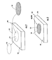
- FIG. 2 is a schematic perspective view of a housing or casing for an implantable medical device according to an exemplary embodiment illustrating the removal of a portion of the housing to form an aperture therein.
- FIG. 3 is a schematic perspective view of the housing shown in FIG. 2 illustrating the welding of a member to the housing in the location of the aperture.
- FIG. 4 is a schematic cross-sectional view of a portion of the housing shown in FIG. 3 illustrating the assembly of the housing according to an exemplary embodiment.
- FIG. 5 is a schematic cross-sectional view of the portion of the housing shown in FIG. 3 illustrating the member provided in place in the aperture.
- FIG. 6 is a schematic cross-sectional view of the portion of the housing shown in FIG. 3 illustrating the welding of the member to the housing.
- FIG. 7 is a graph illustrating the relationship between resistivity and tensile yield strength for a number of titanium alloys.
- FIG. 8 is a graph illustrating the relationship between resistivity and percent elongation for a number of titanium alloys.
- FIG. 9 is a contour plot illustrating the effect of varying amounts of aluminum and vanadium on the resistivity of titanium alloys.
- FIG. 10 is a contour plot illustrating the effect of varying amounts of aluminum and tin on the resistivity of titanium alloys.
- FIG. 11 is a graph illustrating a comparison of tensile yield strengths of various titanium alloys.
- FIG. 12 is a graph illustrating the relationship of percent elongation and stress versus temperature responses for two titanium alloys.
- FIG. 13 is a graph illustrating the relationship between strain rate and temperature responses for two titanium alloys.
- FIG. 14 is a graph illustrating the relationship between effective parallel coil resistance and sheet thickness for a number of titanium alloys.
- FIG. 15 is a graph illustrating the relationship between effective parallel coil resistance and resistivity for a number of titanium alloys.
- FIG. 16 is a graph illustrating the relationship between INS loss and current for two titanium alloys.
- FIG. 17 is a graph illustrating the relationship between charging frequency and coil coupling response for various titanium alloys.
- a housing or casing 20 for an implantable medical device (IMD) 10 in the form of an implantable neurological stimulation (INS) device is shown according to an exemplary embodiment.
- the housing 20 is intended to protect the IME 10 from damage during implantation and use, and is formed of a biocompatible material to prevent undesirable interactions between the IMD 10 and the human body or other organism into which it is implanted.
- the subject matter described herein may also find utility in other types of IMDs according to other exemplary embodiments, including drug pumps, cardiac pacemakers, and the like.
- the IMD 10 includes a coil or winding 50 that is used to charge the EMD 10 by induction when another coil coupled to a charging device is provided proximate the IMD 10 .
- the IMD 10 may be recharged without the need to remove it from the body in which it is implanted (i.e., the charging may occur transdermally).
- the coil is provided inside the housing 20 .
- the coil may be provided outside the housing.
- the housing 20 is formed from at least two different materials.
- a first portion 30 of the housing 20 is formed from a first material and a second portion 40 of the housing 20 is formed from a second material.
- the second portion 40 is a generally flat or planar member that is coupled to the first portion 30 by welding, adhesive, or other means.
- the first portion 30 forms the remainder of the housing.
- FIG. 1 illustrates the use of two materials to form the housing 20
- a different number of materials may be used (e.g., the housing may have three or more different sections, each formed from a different material).
- FIG. 1 illustrates a particular configuration for an MD housing, other types of housings having different sizes, shapes, and configurations may also be used according to other exemplary embodiments.
- FIG. 2 is a schematic view of a housing 120 according to an exemplary embodiment illustrating the removal of a portion 132 of the housing 120 , which leaves an opening or aperture 134 provided in the remaining portion 130 of the housing 120 .
- portion 132 is generally circular in shape, although the portion 132 may have any desired size or shape according to other exemplary embodiments.
- any suitable method may be used to remove the portion 132 from the housing 120 .
- an electrical discharge machining (EDM) process may be used.
- other techniques may be used (e.g., cutting using a water jet, a laser, etc.).
- the aperture 134 may be formed in the housing 120 when the housing is produced (e.g., the housing is molded with the aperture already in place), thus eliminating the need to remove the portion 132 therefrom.
- a member or element shown as a second portion 140 is coupled to the portion 130 of the housing 120 at the location of the aperture 134 such that the housing is effectively sealed.
- the portion 140 is coupled to the portion 130 of the housing 120 by welding (weldments are labeled with reference numeral 150 in FIG. 3 ).
- various welding methods of coupling portion 140 to the portion 130 of the housing 120 may be used (e.g., resist welding, stir friction welding, laser welding, etc.).
- Portion 140 is formed from a material that differs from that of the portion 120 according to an exemplary embodiment. Portion 140 may be formed by cutting it from a larger sheet of material. In certain situations, portion 140 may have a tendency after it is cut to bend upward due to the residual stresses within the material. In such a case, a hot sizing process such as that described in U.S. patent application Ser. No. 11/413,471 filed Apr. 28, 2006 (incorporated by reference herein in its entirety) may be used to provide portion 140 as a substantially flat component.
- FIGS. 4-6 illustrate the steps used in a method of forming the housing 120 according to an exemplary embodiment.
- the portion 140 is aligned with the aperture 134 such that the portion 140 may be coupled to the portion 130 as illustrated in FIG. 5 .
- the portion 130 of the housing includes a cutout configured (e.g., has a “stepped” configuration) for engaging a complementary portion of the portion 140 as the portion 140 is put in place. These cutouts may be formed, for example, by machining the components to remove material to form the geometries shown in FIG. 4 .
- the height of the cutout (as illustrated by arrows “A”) is between approximately 0.001 and 0.0012 inches and the width of the cutout (as illustrated by arrows “B”) is between approximately 0.001 and 0.0012 inches according to an exemplary embodiment, although it should be understood that other dimensions may be used with various other exemplary embodiments.
- the housing 120 is formed as having two separate portions (e.g., portions 130 and 140 ), each formed from different materials.
- the housing it is it is advantageous to select materials that have relatively high tensile yield strengths (to provide improved strength of the housing) while still exhibiting relatively good formability at relatively low temperatures (to allow the manufacture of relatively small components having relatively complex geometries at temperatures between approximately 200° and 400° C., and more preferably at a temperature of approximately 500° C.).
- One advantageous feature of using an alloy that exhibits relatively good formability at relatively low temperatures is that the occurrence of undesirable oxidation during the forming operation may be reduced or eliminated.
- FIG. 7 is a graph illustrating the relationship between resistivity and tensile yield strength for a number of titanium alloys
- FIG. 8 is a graph illustrating the relationship between formability (shown as percent elongation of the alloys) and resistivity of such alloys. From this data, it is evident that resistivity of titanium alloys tends to increase with increasing tensile yield strength. Conversely, the resistivity tends to decrease with increasing formability.
- FIG. 9 is a contour plot illustrating the change in resistivity for titanium-aluminum-vanadium alloys when the percentages of aluminum and vanadium are varied.
- FIG. 10 is a contour plot illustrating the change in resistivity for titanium-aluminum-tin alloys when the percentages of aluminum and tin are varied. As can be seen from these contour plots, the effect on resistivity is different when the aluminum/vanadium percentages are varied as compared to the difference resulting from varying the aluminum/tin percentages.
- the alloy selected is also beneficial for the alloy selected to have relatively good formability performance to allow the alloy to be formed into relatively thin sheets that may be formed into structures having relatively complex geometries (e.g., structures having relatively small features and sharp corners).
- the housing e.g., a “corner” of the housing
- the housing 20 is formed from at least two different materials (e.g., portion 40 is formed from a different material that portion 30 as shown in FIG. 1 ).
- portion 40 is formed from a different material that portion 30 as shown in FIG. 1 .
- One advantageous feature of forming the housing from multiple different materials is that the housing may be tailored to allow enhanced power coupling and recharging efficiency, improved telemetry distance, reduced heating effects during magnetic resonance imaging (MRI), and improved tolerance for compression stress as compared to devices that have housings or casing formed only from a single material such as CP Ti Grade 1.
- a portion of the housing (e.g., portion 40 as shown in FIG. 1 ) is formed from a material that has a higher resistivity than another portion (e.g., portion 30 ) of the housing.
- the higher-resistivity material may have a resistivity of between approximately 100 ⁇ m ⁇ -cm and 210 ⁇ m ⁇ -cm and a tensile yield strength of between approximately 65 ksi and 150 ksi. It is intended that the portion of the housing having the higher resistivity will be aligned with a recharge or telemetry coil provided within the housing to allow for improved power coupling efficiency and telemetry distance for the IMD.
- a portion of the housing is formed from CP Ti Grade 1, while another portion of the housing is formed from another titanium material having a higher resistivity than CP Ti Grade 1.
- both portions of the housing are formed from titanium materials (e.g., alloys) other than CP Ti Grade 1, in which case one of the titanium materials may have a higher resistivity than the other.
- a portion of the housing is made from a titanium (Ti) alloy having the general formula Ti—Al—B—C where B represents one or more alloy elements such as V, Sn, Mo, Nb, Zr, and combinations thereof and C represents one or more impurity elements such as N, C, H, Fe, O, Si, Pd, Ru, and combinations thereof.
- Ti titanium
- B represents one or more alloy elements such as V, Sn, Mo, Nb, Zr, and combinations thereof
- C represents one or more impurity elements such as N, C, H, Fe, O, Si, Pd, Ru, and combinations thereof.
- Aluminum is provided in an amount between approximately 2 and 7 weight percent according to an exemplary embodiment.
- Elements represented by B and C in the above formula may be present in amounts shown in Table 1 according to various exemplary embodiments.
- a portion of the housing may be formed from a titanium alloy having the formula Ti-6Al-4V (referred to as Ti64).
- Ti64 a titanium alloy having the formula Ti-6Al-4V
- Such an alloy has a greater tensile yield strength than CP Ti Grade 1 and also has better power coupling efficiency and improved telemetry distance.
- a portion of the housing may be formed from a titanium alloy having a composition of Ti-4.5Al-3V-2Fe-2Mo-0.15O.
- a titanium alloy having a composition of Ti-4.5Al-3V-2Fe-2Mo-0.15O is commercially available from JFE Steel Corporate of Chiba, Japan under the trade name SP-700. Based on known properties of this alloy, it is believed that such a material will be sufficiently biocompatible to allow its use in implantable medical devices such as INS devices, while also providing enhanced power coupling and recharging efficiency, improved telemetry distance, reduced heating effects during magnetic resonance imaging (MRI), and improved tolerance for compression stress.
- FIG. 11 is a graph illustrating the tensile yield strength of SP-700 alloy as compared to CP Ti Grade 1 and Ti-6Al-4V alloys. As shown, the SP-700 alloy has a tensile yield strength that is approximately three times greater than CP Ti Grade, 1 and also has a higher tensile yield strength than the Ti-6Al-4V alloy. It is intended that this property of the SP-700 alloy will contribute to enhanced strength of the resulting INS packaging and improved resistivity.
- FIG. 12 is a graph illustrating the relationship between percent elongation and temperature for the SP-700 alloy and the Ti-6Al-4V alloy. As evident from the graph, the SP-700 alloy is significantly more formable at lower temperatures as compared to the Ti-6Al-4V alloy. It is intended that by using the SP-700 alloy, relatively thin ( ⁇ 0.4 mm) sheets of the material may be produced which may be formed into housings for INS devices that have relatively complex geometries or shapes. Additionally, as illustrated in FIG. 13 , the SP-700 alloy is less susceptible to hot deformation cracking as compared to Ti-6Al-4V alloys.
- titanium alloys may be used to form portions of the housing.
- One such alloy is commercially available from Allvac of Albany, Oreg. under the trade name ATI425 and having a composition of Ti-4Al-2.5V-1.5Fe-0.25O.
- titanium alloys such as Ti-6Al-2Sn-4Zr-2Mo (Ti6242), Ti-3Al-2.5V (Grade 9), and titanium matrix composites (alpha and near alpha titanium matrix with SiC, TiC, TiO particles distributed therein) may be used.
- Ti-8Al—Mo—V (Ti811) alloy may be used in configurations where a portion of the housing is relatively flat (Ti811 alloy is not as formable as the other alloys described above, but has excellent resistivity values, as illustrated in Table 2 below; accordingly, Ti811 may be used to form portions of housings such as portion 40 illustrated in FIG. 1 ).
- Table 2 illustrates properties of the titanium alloys described above.
- the particular material selected may depend on the desired characteristics of the IMD, the size and shape of the IMD housing, and other factors.
- the SP-700 and Ti-6Al-4V alloys have higher resistivities and tensile yield strengths as compared to CP Ti Grade 1
- the SP-700 alloy has significantly better percent elongation, formability (a subjective measure), and cold rolling reduction limit as compared to the Ti-6Al-4V alloy, which allows it to be formed into sheets that are significantly thinner than those formed from the Ti-6Al-4V alloy (e.g., sheets having a thickness of 0.007 as opposed to sheets having a thickness of 0.016).
- a housing may include a first portion formed from CP Ti Grade 1 and another portion made from a titanium alloy such as Ti-4.5Al-3V-2Fe-2Mo-0.15O, Ti-4Al-2.5V-1.5Fe-0.25O, Ti-6Al-2Sn-4Zr-2Mo, Ti-3Al-2.5V, Ti-6Al-4V, Ti-8Al-1Mo-1V.
- a housing may include a two portions that are each formed from a different titanium alloy (such as those described in the preceding sentence), where one of the materials has a higher resistivity than the other.
- one or more portions of the housing may be made from an alloy comprising a plurality of titanium alloys (e.g., two or more alloys selected from Ti-4.5Al-3V-2Fe-2Mo-0.15O, Ti-4Al-2.5V-1.5Fe-0.25O, Ti-6Al-2Sn-4Zr-2Mo, Ti-3Al-2.5V, Ti-6Al-4V, Ti-8Al-1Mo-1V).
- a plurality of titanium alloys e.g., two or more alloys selected from Ti-4.5Al-3V-2Fe-2Mo-0.15O, Ti-4Al-2.5V-1.5Fe-0.25O, Ti-6Al-2Sn-4Zr-2Mo, Ti-3Al-2.5V, Ti-6Al-4V, Ti-8Al-1Mo-1V.
- the particular materials selected may vary depending on the intended application and other factors.
- FIG. 14 illustrates the relationship between the effective parallel coil resistance (Rp 1 ) and housing thickness for housings formed from various titanium alloys at a charging frequency of 175 kHz.
- the effective parallel coil resistance tends to decrease with increasing housing thickness.
- the effective parallel coil resistance also tends to increase with increasing resistivity; thus, one would expect that alloys having relatively high resistivities will also exhibit relatively good effective parallel coil resistance.
- housings formed from the Ti811 alloy exhibit effective parallel coil resistance that is comparable to or greater than housings formed from the Ti-6Al-4V alloy, while housings formed from the ATI425 alloy exhibit effective parallel coil resistance that is less than those formed from the Ti-6Al-4V alloy. Because the resistivity of the SP-700 alloy is comparable to that of the Ti-6Al-4V alloy, it is expected that the effective parallel coil resistance of these two alloys will also be similar.
- FIG. 16 illustrates the relationship between current and the INS loss for devices having housings made using two different alloys.
- the devices having housings formed from the ATI425 alloy exhibit less INS loss at given amounts of current as compared to those having housings formed from the CP Ti Grade 1 alloy.
- housings formed from ATI425 alloys would exhibit improved charging efficiency as compared to those formed from Ti Grade 1 alloys.
- FIG. 17 illustrates the relationship between charging frequency and coil coupling for devices having housings formed from various titanium alloys.
- the coil voltage coupling from 8 kHz to 175 kHz was first measured for a ten centimeter air gap between the charging coils for reference purposes, after which the coil voltage coupling was measured using sheet material inserted between the inductive charging coils.
- alloys described herein e.g., Ti-6Al-4V, SP-700, ATI425, Ti811, Ti-3Al-2.5V, Ti6242, and titanium matrix composites (alpha and near alpha titanium matrix with SiC, TiC, TiO particles distributed therein)
- devices using such alloys may have improved recharging efficiency (e.g., such devices may have an approximately 8 dB power coupling increase for recharging frequencies over 50 kHz as compared to devices having housings formed from CP Ti Grade 1 alloy). This may result in an approximately tenfold increase in power transfer.
- the portions of the housings using such materials may be formed having thinner walls, which contribute to the improved telemetry distance and power coupling efficiency.
- the housing includes portions having thicknesses of between approximately 0.01 and 0.016 inches. According to other exemplary embodiments, the portions have thicknesses of between approximately 0.01 and 0.012 inches.
- titanium alloys such as those described herein may be used in connection with other implantable medical devices as well, such as drug pumps, cardiac catheters, and the like.
- the titanium alloys described herein may be used as a diaphragm material for an IMD in the form of an implantable pressure sensor (e.g., which may be integrated into a drug pump as a catheter diagnostic aid). Because diaphragms made from CP titanium (Ti) Grade 1 must be relatively thick, the signal to noise ratio of the sensor is relatively high.
- Ti-6Al-4V will help increase both strength and the signal to noise ratio
- such an alloy is not available in sheets thin enough for practical sensors.
- the titanium alloys described herein offer the possibility of a sensor with higher signal to noise ratios that also meet the overpressure requirements for such components.
- the titanium alloys described herein may also find utility as housing materials for IMDs in the form of cardiac pacemakers.
- the titanium alloys described herein may be used as an outer shield for a drug pump.
- One advantageous feature of utilizing the alloys described herein is that it is believed that the use of such alloys may improve the efficiency of telemetry of the pump in a similar manner to that described above in the context of implantable INS devices.
- housings may be made from other biologically-compatible materials.
- a housing may include a first portion formed from titanium and a titanium alloy and a second portion formed from a ceramic matrix material having a metal incorporated therein as reinforcement.
- the edges of the ceramic matrix portion may be provided with metallic features (e.g., edges) configured to allow the portion to be welded to the titanium or titanium alloy portion (e.g., metal could be fused along the edges of the ceramic matrix portion).
Landscapes
- Health & Medical Sciences (AREA)
- Epidemiology (AREA)
- Animal Behavior & Ethology (AREA)
- Heart & Thoracic Surgery (AREA)
- Surgery (AREA)
- Vascular Medicine (AREA)
- Chemical & Material Sciences (AREA)
- Life Sciences & Earth Sciences (AREA)
- Inorganic Chemistry (AREA)
- General Health & Medical Sciences (AREA)
- Public Health (AREA)
- Veterinary Medicine (AREA)
- Materials For Medical Uses (AREA)
- Electrotherapy Devices (AREA)
- External Artificial Organs (AREA)
Priority Applications (6)
| Application Number | Priority Date | Filing Date | Title |
|---|---|---|---|
| US11/590,250 US8380311B2 (en) | 2006-10-31 | 2006-10-31 | Housing for implantable medical device |
| EP07749088A EP2117619B1 (de) | 2006-10-31 | 2007-01-23 | Titangehäuse für ein implantierbares medizinprodukt |
| AT07749088T ATE504319T1 (de) | 2006-10-31 | 2007-01-23 | Titangehäuse für ein implantierbares medizinprodukt |
| DE602007013808T DE602007013808D1 (de) | 2006-10-31 | 2007-01-23 | Titangehäuse für ein implantierbares medizinprodukt |
| PCT/US2007/001763 WO2008054439A1 (en) | 2006-10-31 | 2007-01-23 | Titanium housing for implantable medical device |
| US12/186,855 US8401648B2 (en) | 2006-10-31 | 2008-08-06 | Housing for implantable medical device |
Applications Claiming Priority (1)
| Application Number | Priority Date | Filing Date | Title |
|---|---|---|---|
| US11/590,250 US8380311B2 (en) | 2006-10-31 | 2006-10-31 | Housing for implantable medical device |
Related Child Applications (2)
| Application Number | Title | Priority Date | Filing Date |
|---|---|---|---|
| US12/186,855 Continuation-In-Part US8401648B2 (en) | 2006-10-31 | 2008-08-06 | Housing for implantable medical device |
| US12/956,158 Division US20110104284A1 (en) | 2004-02-27 | 2010-11-30 | Hyaluronic acid derivative based three-dimensional matrix |
Publications (2)
| Publication Number | Publication Date |
|---|---|
| US20080103556A1 US20080103556A1 (en) | 2008-05-01 |
| US8380311B2 true US8380311B2 (en) | 2013-02-19 |
Family
ID=38255245
Family Applications (1)
| Application Number | Title | Priority Date | Filing Date |
|---|---|---|---|
| US11/590,250 Active 2030-01-28 US8380311B2 (en) | 2006-10-31 | 2006-10-31 | Housing for implantable medical device |
Country Status (5)
| Country | Link |
|---|---|
| US (1) | US8380311B2 (de) |
| EP (1) | EP2117619B1 (de) |
| AT (1) | ATE504319T1 (de) |
| DE (1) | DE602007013808D1 (de) |
| WO (1) | WO2008054439A1 (de) |
Cited By (3)
| Publication number | Priority date | Publication date | Assignee | Title |
|---|---|---|---|---|
| US20080103543A1 (en) * | 2006-10-31 | 2008-05-01 | Medtronic, Inc. | Implantable medical device with titanium alloy housing |
| US20160157371A1 (en) * | 2014-12-02 | 2016-06-02 | Heraeus Precious Metals Gmbh & Co. Kg | Implantable medical device housing having integrated features |
| US20180263132A1 (en) * | 2014-12-24 | 2018-09-13 | Medtronic, Inc. | Implantable medical devices and methods of forming same |
Families Citing this family (22)
| Publication number | Priority date | Publication date | Assignee | Title |
|---|---|---|---|---|
| EP2034885A4 (de) | 2006-06-23 | 2010-12-01 | Neurovista Corp | Minimal invasive überwachungssysteme und -verfahren |
| US8295934B2 (en) | 2006-11-14 | 2012-10-23 | Neurovista Corporation | Systems and methods of reducing artifact in neurological stimulation systems |
| WO2008092133A2 (en) * | 2007-01-25 | 2008-07-31 | Neurovista Corporation | Methods and systems for measuring a subject's susceptibility to a seizure |
| EP2126785A2 (de) * | 2007-01-25 | 2009-12-02 | NeuroVista Corporation | Systeme und verfahren zur identifikation des kontra-iktalen zustands eines patienten |
| US8036736B2 (en) | 2007-03-21 | 2011-10-11 | Neuro Vista Corporation | Implantable systems and methods for identifying a contra-ictal condition in a subject |
| US7801613B2 (en) * | 2007-04-26 | 2010-09-21 | Medtronic, Inc. | Metal injection molded titanium alloy housing for implantable medical devices |
| US9788744B2 (en) * | 2007-07-27 | 2017-10-17 | Cyberonics, Inc. | Systems for monitoring brain activity and patient advisory device |
| US9259591B2 (en) * | 2007-12-28 | 2016-02-16 | Cyberonics, Inc. | Housing for an implantable medical device |
| US20090171168A1 (en) | 2007-12-28 | 2009-07-02 | Leyde Kent W | Systems and Method for Recording Clinical Manifestations of a Seizure |
| US8849390B2 (en) | 2008-12-29 | 2014-09-30 | Cyberonics, Inc. | Processing for multi-channel signals |
| US8588933B2 (en) | 2009-01-09 | 2013-11-19 | Cyberonics, Inc. | Medical lead termination sleeve for implantable medical devices |
| US8359098B2 (en) * | 2009-05-29 | 2013-01-22 | Medtronic, Inc. | Implantable medical device with exposed generator |
| US9099720B2 (en) | 2009-05-29 | 2015-08-04 | Medtronic, Inc. | Elongate battery for implantable medical device |
| US8786624B2 (en) | 2009-06-02 | 2014-07-22 | Cyberonics, Inc. | Processing for multi-channel signals |
| US8987632B2 (en) * | 2009-10-09 | 2015-03-24 | The United States Of America As Represented By The Administrator Of The National Aeronautics And Space Administration | Modification of surface energy via direct laser ablative surface patterning |
| US9643019B2 (en) | 2010-02-12 | 2017-05-09 | Cyberonics, Inc. | Neurological monitoring and alerts |
| US8594806B2 (en) | 2010-04-30 | 2013-11-26 | Cyberonics, Inc. | Recharging and communication lead for an implantable device |
| US9630231B2 (en) * | 2012-01-27 | 2017-04-25 | Nuvectra Corporation | Superplastic forming for titanium implant enclosures |
| US9981137B2 (en) | 2012-01-27 | 2018-05-29 | Nuvectra Corporation | Heat dispersion for implantable medical devices |
| US20150066113A1 (en) * | 2013-09-05 | 2015-03-05 | Boston Scientific Neuromodulation Corporation | Radiolucent Metal Case Plate to Facilitate Communications in an Implantable Medical Device |
| WO2016149114A1 (en) * | 2015-03-16 | 2016-09-22 | Boston Scientific Neuromodulation Corporation | Composite metal container for control module of electrical stimulation systems and methods of making and using |
| US12589244B2 (en) * | 2019-12-23 | 2026-03-31 | Medtronic, Inc. | Ceramic-to-metal joint for implantable pulse generators |
Citations (25)
| Publication number | Priority date | Publication date | Assignee | Title |
|---|---|---|---|---|
| US4041955A (en) | 1976-01-29 | 1977-08-16 | Pacesetter Systems Inc. | Implantable living tissue stimulator with an improved hermetic metal container |
| EP0099874A1 (de) | 1982-07-15 | 1984-02-01 | Vereinigte Edelstahlwerke Aktiengesellschaft (Vew) | Ziehwerkzeug |
| DE3740732A1 (de) | 1987-01-28 | 1988-08-11 | Ohara Co | Dentalgussstuecke aus titanlegierung |
| WO1990006108A1 (fr) | 1988-11-25 | 1990-06-14 | Dainippon Ink And Chemicals, Inc. | Agent anti-inflammatoire polyvalent |
| EP0534782A1 (de) | 1991-09-26 | 1993-03-31 | Medtronic, Inc. | Gehäuse für implantierbare medizinische Vorrichtung |
| US5423881A (en) * | 1994-03-14 | 1995-06-13 | Medtronic, Inc. | Medical electrical lead |
| US5470345A (en) | 1994-06-16 | 1995-11-28 | Medtronic, Inc. | Implantable medical device with multi-layered ceramic enclosure |
| WO1995034342A1 (en) | 1994-06-16 | 1995-12-21 | Medtronic, Inc. | Implantable ceramic device enclosure |
| US5782891A (en) | 1994-06-16 | 1998-07-21 | Medtronic, Inc. | Implantable ceramic enclosure for pacing, neurological, and other medical applications in the human body |
| US5895414A (en) * | 1996-04-19 | 1999-04-20 | Sanchez-Zambrano; Sergio | Pacemaker housing |
| US6067474A (en) | 1997-08-01 | 2000-05-23 | Advanced Bionics Corporation | Implantable device with improved battery recharging and powering configuration |
| WO2001097908A2 (en) | 2000-06-16 | 2001-12-27 | Medtronic, Inc. | An implantable medical device with aregarding coil magnetic shield |
| US20020042630A1 (en) * | 2000-09-18 | 2002-04-11 | Cameron Health, Inc. | Canister designs for implantable cardioverter-defibrillators |
| US6411854B1 (en) | 1998-04-30 | 2002-06-25 | Advanced Bionics Corporation | Implanted ceramic case with enhanced ceramic case strength |
| US6414835B1 (en) * | 2000-03-01 | 2002-07-02 | Medtronic, Inc. | Capacitive filtered feedthrough array for an implantable medical device |
| US20020103510A1 (en) | 2000-09-18 | 2002-08-01 | Cameron Health, Inc. | Flexible subcutaneous implantable cardioverter-defibrillator |
| US6516227B1 (en) | 1999-07-27 | 2003-02-04 | Advanced Bionics Corporation | Rechargeable spinal cord stimulator system |
| US20030078675A1 (en) | 2001-03-09 | 2003-04-24 | Wolfgang Daum | Material for nuclear spin tomography MRI or magnetic resonance imaging (prototype) |
| US20030120320A1 (en) * | 2001-12-20 | 2003-06-26 | Medtronic,Inc. | Implantable medical device having a housing or component case with an insulating material formed thereon, and methods of making same |
| US6596439B1 (en) | 2000-04-26 | 2003-07-22 | Quallion Llc | Lithium ion battery capable of being discharged to zero volts |
| US20040093039A1 (en) * | 2002-10-25 | 2004-05-13 | Raphael Schumert | Gastrointestinal pacemaker |
| EP1424098A1 (de) | 1997-08-01 | 2004-06-02 | Alfred E. Mann Foundation For Scientific Research | Implantierbare Einrichtung mit verbesserter Anordnung zur Ladung der Batterie und zur Energiezufuhr |
| US20050075700A1 (en) * | 2003-10-02 | 2005-04-07 | Medtronic, Inc. | External power source for an implantable medical device having an adjustable magnetic core and system and method related therefore |
| US20050107835A1 (en) | 2000-09-18 | 2005-05-19 | Cameron Health, Inc. | Ceramics and/or other material insulated shell for active and non-active S-ICD can |
| US20050149139A1 (en) | 2003-12-03 | 2005-07-07 | Gianni Plicchi | System of antenna for electromedical devices implantable in the human body |
Family Cites Families (1)
| Publication number | Priority date | Publication date | Assignee | Title |
|---|---|---|---|---|
| US5872891A (en) * | 1996-05-24 | 1999-02-16 | Son; Jae S. | System for providing substantially instantaneous hot water |
-
2006
- 2006-10-31 US US11/590,250 patent/US8380311B2/en active Active
-
2007
- 2007-01-23 AT AT07749088T patent/ATE504319T1/de not_active IP Right Cessation
- 2007-01-23 EP EP07749088A patent/EP2117619B1/de not_active Not-in-force
- 2007-01-23 DE DE602007013808T patent/DE602007013808D1/de active Active
- 2007-01-23 WO PCT/US2007/001763 patent/WO2008054439A1/en not_active Ceased
Patent Citations (26)
| Publication number | Priority date | Publication date | Assignee | Title |
|---|---|---|---|---|
| US4041955A (en) | 1976-01-29 | 1977-08-16 | Pacesetter Systems Inc. | Implantable living tissue stimulator with an improved hermetic metal container |
| EP0099874A1 (de) | 1982-07-15 | 1984-02-01 | Vereinigte Edelstahlwerke Aktiengesellschaft (Vew) | Ziehwerkzeug |
| DE3740732A1 (de) | 1987-01-28 | 1988-08-11 | Ohara Co | Dentalgussstuecke aus titanlegierung |
| WO1990006108A1 (fr) | 1988-11-25 | 1990-06-14 | Dainippon Ink And Chemicals, Inc. | Agent anti-inflammatoire polyvalent |
| EP0534782A1 (de) | 1991-09-26 | 1993-03-31 | Medtronic, Inc. | Gehäuse für implantierbare medizinische Vorrichtung |
| US5423881A (en) * | 1994-03-14 | 1995-06-13 | Medtronic, Inc. | Medical electrical lead |
| US5470345A (en) | 1994-06-16 | 1995-11-28 | Medtronic, Inc. | Implantable medical device with multi-layered ceramic enclosure |
| WO1995034342A1 (en) | 1994-06-16 | 1995-12-21 | Medtronic, Inc. | Implantable ceramic device enclosure |
| US5782891A (en) | 1994-06-16 | 1998-07-21 | Medtronic, Inc. | Implantable ceramic enclosure for pacing, neurological, and other medical applications in the human body |
| US5895414A (en) * | 1996-04-19 | 1999-04-20 | Sanchez-Zambrano; Sergio | Pacemaker housing |
| US6067474A (en) | 1997-08-01 | 2000-05-23 | Advanced Bionics Corporation | Implantable device with improved battery recharging and powering configuration |
| EP1424098A1 (de) | 1997-08-01 | 2004-06-02 | Alfred E. Mann Foundation For Scientific Research | Implantierbare Einrichtung mit verbesserter Anordnung zur Ladung der Batterie und zur Energiezufuhr |
| US6411854B1 (en) | 1998-04-30 | 2002-06-25 | Advanced Bionics Corporation | Implanted ceramic case with enhanced ceramic case strength |
| US6516227B1 (en) | 1999-07-27 | 2003-02-04 | Advanced Bionics Corporation | Rechargeable spinal cord stimulator system |
| US6414835B1 (en) * | 2000-03-01 | 2002-07-02 | Medtronic, Inc. | Capacitive filtered feedthrough array for an implantable medical device |
| US6596439B1 (en) | 2000-04-26 | 2003-07-22 | Quallion Llc | Lithium ion battery capable of being discharged to zero volts |
| US20050113888A1 (en) | 2000-06-16 | 2005-05-26 | Medtronic, Inc. | Implantable medical device & electrical stimulation device with magnetic shield |
| WO2001097908A2 (en) | 2000-06-16 | 2001-12-27 | Medtronic, Inc. | An implantable medical device with aregarding coil magnetic shield |
| US20020042630A1 (en) * | 2000-09-18 | 2002-04-11 | Cameron Health, Inc. | Canister designs for implantable cardioverter-defibrillators |
| US20050107835A1 (en) | 2000-09-18 | 2005-05-19 | Cameron Health, Inc. | Ceramics and/or other material insulated shell for active and non-active S-ICD can |
| US20020103510A1 (en) | 2000-09-18 | 2002-08-01 | Cameron Health, Inc. | Flexible subcutaneous implantable cardioverter-defibrillator |
| US20030078675A1 (en) | 2001-03-09 | 2003-04-24 | Wolfgang Daum | Material for nuclear spin tomography MRI or magnetic resonance imaging (prototype) |
| US20030120320A1 (en) * | 2001-12-20 | 2003-06-26 | Medtronic,Inc. | Implantable medical device having a housing or component case with an insulating material formed thereon, and methods of making same |
| US20040093039A1 (en) * | 2002-10-25 | 2004-05-13 | Raphael Schumert | Gastrointestinal pacemaker |
| US20050075700A1 (en) * | 2003-10-02 | 2005-04-07 | Medtronic, Inc. | External power source for an implantable medical device having an adjustable magnetic core and system and method related therefore |
| US20050149139A1 (en) | 2003-12-03 | 2005-07-07 | Gianni Plicchi | System of antenna for electromedical devices implantable in the human body |
Non-Patent Citations (14)
| Title |
|---|
| Advisory Action for U.S. Appl. No. 11/590,678, mail date Sep. 14, 2011, 3 pages. |
| Amendment and Reply for U.S. Appl. No. 11/590,678, mail date Apr. 15, 2011, 12 pages. |
| Amendment and Reply for U.S. Appl. No. 11/590,678, mail date Aug. 10, 2009, 7 pages. |
| Amendment and Reply for U.S. Appl. No. 11/590,678, mail date Feb. 23, 2010, 10 pages. |
| International Search Report and Written Opinion for Application No. PCT/US2007/001763, date of mailing Sep. 28, 2007, 10 pages. |
| International Search Report and Written Opinion for Application No. PCT/US2007/002042, date of mailing Sep. 28, 2007, 10 pages. |
| Komotori, J. et al., "Corrosion response of surface engineered titanium alloys damaged by prior abrasion," WEAR, 2001, cover and pp. 1239-1249, vol. 251, Elsevier Science B.V. |
| Office Action for U.S. Appl. No. 11/590,678, mail date Dec. 15, 2010, 10 pages. |
| Office Action for U.S. Appl. No. 11/590,678, mail date Jun. 21, 2011, 9 pages. |
| Office Action for U.S. Appl. No. 11/590,678, mail date Jun. 8, 2010, 9 pages. |
| Office Action for U.S. Appl. No. 11/590,678, mail date Nov. 25, 2009, 7 pages. |
| Reply for U.S. Appl. No. 11/590,678, mail date Aug. 22, 2011, 13 pages. |
| Request for Continued Examination and Amendment and Reply for U.S. Appl. No. 11/590,678, mail date Oct. 20, 2011, 25 pages. |
| Request for Continued Examination and Reply for U.S. Appl. No. 11/590,678, mail date Sep. 8, 2010, 16 pages. |
Cited By (6)
| Publication number | Priority date | Publication date | Assignee | Title |
|---|---|---|---|---|
| US20080103543A1 (en) * | 2006-10-31 | 2008-05-01 | Medtronic, Inc. | Implantable medical device with titanium alloy housing |
| US20160157371A1 (en) * | 2014-12-02 | 2016-06-02 | Heraeus Precious Metals Gmbh & Co. Kg | Implantable medical device housing having integrated features |
| US9757573B2 (en) * | 2014-12-02 | 2017-09-12 | Heraeus Deutschland GmbH & Co. KG | Implantable medical device housing having integrated features |
| US9968793B2 (en) | 2014-12-02 | 2018-05-15 | Heraeus Deutschland GmbH & Co. KG | Method of fabricating a housing for an implantable medical device having integrated features |
| US9968792B2 (en) | 2014-12-02 | 2018-05-15 | Heraeus Deutschland GmbH & Co. KG | Implantable medical device housing having integrated features |
| US20180263132A1 (en) * | 2014-12-24 | 2018-09-13 | Medtronic, Inc. | Implantable medical devices and methods of forming same |
Also Published As
| Publication number | Publication date |
|---|---|
| US20080103556A1 (en) | 2008-05-01 |
| ATE504319T1 (de) | 2011-04-15 |
| EP2117619B1 (de) | 2011-04-06 |
| WO2008054439A1 (en) | 2008-05-08 |
| DE602007013808D1 (de) | 2011-05-19 |
| EP2117619A1 (de) | 2009-11-18 |
Similar Documents
| Publication | Publication Date | Title |
|---|---|---|
| EP2117619B1 (de) | Titangehäuse für ein implantierbares medizinprodukt | |
| EP2117618B1 (de) | Implantierbares medizinprodukt mit gehäuse aus einer titanlegierung | |
| US8401648B2 (en) | Housing for implantable medical device | |
| US7801613B2 (en) | Metal injection molded titanium alloy housing for implantable medical devices | |
| US7564674B2 (en) | Feedthrough filter capacitor assemblies having low cost terminal pins | |
| US9259591B2 (en) | Housing for an implantable medical device | |
| CN112312961B (zh) | 用于可植入医疗装置的接收线圈配置 | |
| EP2398026B1 (de) | Beschichtung von nicht lötbarem grundmetall für eine lötanwendung in medizinischer vorrichtungskomponente | |
| EP3541472B1 (de) | Implantierbare medizinische vorrichtung mit einem magnetisch permeablen gehäuse und einer um das gehäuse herum angeordneten induktiven spule | |
| EP1820534A2 (de) | Nanotitan zur Herstellung medizinisch implantierbarer hermetischer Durchführungsanordnungen | |
| AU2020286372B2 (en) | Magnesium-based absorbable alloys | |
| US20210187291A1 (en) | Ceramic-to-metal joint for implantable pulse generators | |
| EP3192608A1 (de) | Mehrfach segementierter intravaskular-führungsdraht ; verfahren zur bekämpfung von rückpralleffekten beim festkörperwiderstandsschweissen von unterschiedlichen materialien | |
| EP3156100A1 (de) | Mrt-kompatible leiterspule | |
| US20170197084A1 (en) | Superplastic forming for titanium implant enclosures | |
| WO2015020724A1 (en) | Guide wire with core made from low-modulus cobalt-chromium alloy | |
| US9269498B2 (en) | Sintered capacitor electrode including multiple thicknesses | |
| US20150066113A1 (en) | Radiolucent Metal Case Plate to Facilitate Communications in an Implantable Medical Device | |
| CN101801454A (zh) | 用于植入物的冲击防护 | |
| US20140212688A1 (en) | High grade titanium alloy sheet and method of making same | |
| US12318619B2 (en) | Medical leads and techniques for manufacturing the same | |
| CN111167860B (zh) | 一种Nb包覆NiTi形状记忆复合材料及其制备方法 | |
| EP2968958B1 (de) | Medizinische leitungen und verfahren zur herstellung davon | |
| KR20250110725A (ko) | 고강도 금속 캔 및 이에 수용된 이차전지 | |
| WO2007127073A2 (en) | System and method for producing component for medical device |
Legal Events
| Date | Code | Title | Description |
|---|---|---|---|
| AS | Assignment |
Owner name: MEDTRONIC, INC., MINNESOTA Free format text: ASSIGNMENT OF ASSIGNORS INTEREST;ASSIGNORS:LI, BERNARD Q.;GREVIOUS, JOHN J.;DAVIS, TIMOTHY J.;AND OTHERS;REEL/FRAME:018754/0870 Effective date: 20061213 |
|
| STCF | Information on status: patent grant |
Free format text: PATENTED CASE |
|
| CC | Certificate of correction | ||
| FPAY | Fee payment |
Year of fee payment: 4 |
|
| MAFP | Maintenance fee payment |
Free format text: PAYMENT OF MAINTENANCE FEE, 8TH YEAR, LARGE ENTITY (ORIGINAL EVENT CODE: M1552); ENTITY STATUS OF PATENT OWNER: LARGE ENTITY Year of fee payment: 8 |
|
| MAFP | Maintenance fee payment |
Free format text: PAYMENT OF MAINTENANCE FEE, 12TH YEAR, LARGE ENTITY (ORIGINAL EVENT CODE: M1553); ENTITY STATUS OF PATENT OWNER: LARGE ENTITY Year of fee payment: 12 |