US8360447B2 - Airline cart - Google Patents
Airline cart Download PDFInfo
- Publication number
- US8360447B2 US8360447B2 US12/935,267 US93526709A US8360447B2 US 8360447 B2 US8360447 B2 US 8360447B2 US 93526709 A US93526709 A US 93526709A US 8360447 B2 US8360447 B2 US 8360447B2
- Authority
- US
- United States
- Prior art keywords
- door
- lock
- trolley according
- cabinet
- shaped body
- Prior art date
- Legal status (The legal status is an assumption and is not a legal conclusion. Google has not performed a legal analysis and makes no representation as to the accuracy of the status listed.)
- Active, expires
Links
Images


Classifications
-
- A—HUMAN NECESSITIES
- A47—FURNITURE; DOMESTIC ARTICLES OR APPLIANCES; COFFEE MILLS; SPICE MILLS; SUCTION CLEANERS IN GENERAL
- A47B—TABLES; DESKS; OFFICE FURNITURE; CABINETS; DRAWERS; GENERAL DETAILS OF FURNITURE
- A47B31/00—Service or tea tables, trolleys, or wagons
-
- B—PERFORMING OPERATIONS; TRANSPORTING
- B62—LAND VEHICLES FOR TRAVELLING OTHERWISE THAN ON RAILS
- B62B—HAND-PROPELLED VEHICLES, e.g. HAND CARTS OR PERAMBULATORS; SLEDGES
- B62B3/00—Hand carts having more than one axis carrying transport wheels; Steering devices therefor; Equipment therefor
- B62B3/002—Hand carts having more than one axis carrying transport wheels; Steering devices therefor; Equipment therefor characterised by a rectangular shape, involving sidewalls or racks
- B62B3/003—Non-transparent side walls
-
- B—PERFORMING OPERATIONS; TRANSPORTING
- B62—LAND VEHICLES FOR TRAVELLING OTHERWISE THAN ON RAILS
- B62B—HAND-PROPELLED VEHICLES, e.g. HAND CARTS OR PERAMBULATORS; SLEDGES
- B62B3/00—Hand carts having more than one axis carrying transport wheels; Steering devices therefor; Equipment therefor
- B62B3/002—Hand carts having more than one axis carrying transport wheels; Steering devices therefor; Equipment therefor characterised by a rectangular shape, involving sidewalls or racks
- B62B3/004—Details of doors or cover lids
-
- B—PERFORMING OPERATIONS; TRANSPORTING
- B62—LAND VEHICLES FOR TRAVELLING OTHERWISE THAN ON RAILS
- B62B—HAND-PROPELLED VEHICLES, e.g. HAND CARTS OR PERAMBULATORS; SLEDGES
- B62B3/00—Hand carts having more than one axis carrying transport wheels; Steering devices therefor; Equipment therefor
- B62B3/002—Hand carts having more than one axis carrying transport wheels; Steering devices therefor; Equipment therefor characterised by a rectangular shape, involving sidewalls or racks
- B62B3/005—Details of storage means, e.g. drawers, bins or racks
-
- B—PERFORMING OPERATIONS; TRANSPORTING
- B62—LAND VEHICLES FOR TRAVELLING OTHERWISE THAN ON RAILS
- B62B—HAND-PROPELLED VEHICLES, e.g. HAND CARTS OR PERAMBULATORS; SLEDGES
- B62B3/00—Hand carts having more than one axis carrying transport wheels; Steering devices therefor; Equipment therefor
- B62B3/006—Hand carts having more than one axis carrying transport wheels; Steering devices therefor; Equipment therefor for stacking objects like trays, bobbins, chains
-
- E—FIXED CONSTRUCTIONS
- E05—LOCKS; KEYS; WINDOW OR DOOR FITTINGS; SAFES
- E05C—BOLTS OR FASTENING DEVICES FOR WINGS, SPECIALLY FOR DOORS OR WINDOWS
- E05C19/00—Other devices specially designed for securing wings, e.g. with suction cups
- E05C19/001—Other devices specially designed for securing wings, e.g. with suction cups with bolts extending over a considerable extent, e.g. nearly along the whole length of at least one side of the wing
-
- A—HUMAN NECESSITIES
- A47—FURNITURE; DOMESTIC ARTICLES OR APPLIANCES; COFFEE MILLS; SPICE MILLS; SUCTION CLEANERS IN GENERAL
- A47B—TABLES; DESKS; OFFICE FURNITURE; CABINETS; DRAWERS; GENERAL DETAILS OF FURNITURE
- A47B31/00—Service or tea tables, trolleys, or wagons
- A47B2031/002—Catering trolleys
-
- B—PERFORMING OPERATIONS; TRANSPORTING
- B62—LAND VEHICLES FOR TRAVELLING OTHERWISE THAN ON RAILS
- B62B—HAND-PROPELLED VEHICLES, e.g. HAND CARTS OR PERAMBULATORS; SLEDGES
- B62B2202/00—Indexing codes relating to type or characteristics of transported articles
- B62B2202/67—Service trolleys, e.g. in aircraft
-
- E—FIXED CONSTRUCTIONS
- E05—LOCKS; KEYS; WINDOW OR DOOR FITTINGS; SAFES
- E05C—BOLTS OR FASTENING DEVICES FOR WINGS, SPECIALLY FOR DOORS OR WINDOWS
- E05C9/00—Arrangements of simultaneously actuated bolts or other securing devices at well-separated positions on the same wing
- E05C9/02—Arrangements of simultaneously actuated bolts or other securing devices at well-separated positions on the same wing with one sliding bar for fastening when moved in one direction and unfastening when moved in opposite direction; with two sliding bars moved in the same direction when fastening or unfastening
-
- E—FIXED CONSTRUCTIONS
- E05—LOCKS; KEYS; WINDOW OR DOOR FITTINGS; SAFES
- E05D—HINGES OR SUSPENSION DEVICES FOR DOORS, WINDOWS OR WINGS
- E05D3/00—Hinges with pins
- E05D3/06—Hinges with pins with two or more pins
- E05D3/12—Hinges with pins with two or more pins with two parallel pins and one arm
-
- E—FIXED CONSTRUCTIONS
- E05—LOCKS; KEYS; WINDOW OR DOOR FITTINGS; SAFES
- E05Y—INDEXING SCHEME RELATING TO HINGES OR OTHER SUSPENSION DEVICES FOR DOORS, WINDOWS OR WINGS AND DEVICES FOR MOVING WINGS INTO OPEN OR CLOSED POSITION, CHECKS FOR WINGS AND WING FITTINGS NOT OTHERWISE PROVIDED FOR, CONCERNED WITH THE FUNCTIONING OF THE WING
- E05Y2900/00—Application of doors, windows, wings or fittings thereof
- E05Y2900/20—Application of doors, windows, wings or fittings thereof for furnitures, e.g. cabinets
-
- Y—GENERAL TAGGING OF NEW TECHNOLOGICAL DEVELOPMENTS; GENERAL TAGGING OF CROSS-SECTIONAL TECHNOLOGIES SPANNING OVER SEVERAL SECTIONS OF THE IPC; TECHNICAL SUBJECTS COVERED BY FORMER USPC CROSS-REFERENCE ART COLLECTIONS [XRACs] AND DIGESTS
- Y10—TECHNICAL SUBJECTS COVERED BY FORMER USPC
- Y10T—TECHNICAL SUBJECTS COVERED BY FORMER US CLASSIFICATION
- Y10T292/00—Closure fasteners
- Y10T292/08—Bolts
- Y10T292/0801—Multiple
- Y10T292/0803—Sliding and swinging
- Y10T292/0805—Combined motion
- Y10T292/0806—Lever-operating means
-
- Y—GENERAL TAGGING OF NEW TECHNOLOGICAL DEVELOPMENTS; GENERAL TAGGING OF CROSS-SECTIONAL TECHNOLOGIES SPANNING OVER SEVERAL SECTIONS OF THE IPC; TECHNICAL SUBJECTS COVERED BY FORMER USPC CROSS-REFERENCE ART COLLECTIONS [XRACs] AND DIGESTS
- Y10—TECHNICAL SUBJECTS COVERED BY FORMER USPC
- Y10T—TECHNICAL SUBJECTS COVERED BY FORMER US CLASSIFICATION
- Y10T292/00—Closure fasteners
- Y10T292/08—Bolts
- Y10T292/0801—Multiple
- Y10T292/0807—Sliding and hooked end
Definitions
- the invention relates in general to a catering trolley or serving trolley (cart) for use in airplanes.
- Such catering trolleys or carts are generally known. They comprise a cabinet-shaped body, at least one door, an upper panel, wheels, etc.
- the trolleys are used for presenting for instance meals and drinks, or other articles, to airplane passengers, the trolleys riding through the aisle of the airplane, pushed or pulled by the serving cabin personnel.
- a first requirement concerns safety and strength.
- the carts must be able to withstand heavy loads, and must meet severe fire-safety requirements.
- carts are traditionally made of aluminum, in which case for instance wall panels are fixed to a frame. Hinges for a door, and a latch mechanism for the door, are also attached to this frame.
- this has some disadvantages. Because the aluminum carts consist of multiple aluminum parts, manufacturing and assembling is relatively expensive. Further, aluminum is susceptible to damages such as dents and cracks, and is therefore relatively expensive in maintenance. Furthermore, an important disadvantage is that aluminum carts are relatively heavy, while especially in the world of airplanes there exists a desire for as much weight reduction as possible.
- the present invention aims in general to solve or at least reduce the said disadvantages.
- the present invention aims to provide a cart with a relatively low weight, of which the costs of manufacturing and maintenance are relatively low, while nevertheless the requirements of safety and strength are met.
- the present invention proposes to manufacture the cart from plastic as much as possible.
- the same inventor has already proposed to manufacture the cabinet body as a self-supporting extrusion part from plastic.
- the design of the door is described summarily only.
- the present invention relates to the design of the door. According to an important aspect of the present invention, it is proposed to manufacture the door from plastic for at least a large part.
- An evidently important characteristic of a door is that it can not only be easily opened and closed, but also that it remains closed in the closed condition under extreme circumstances. Particularly, strength requirements are set to a door in conjunction with unexpected shock movements, coming to expression in a punch-shaped load from the inside. The construction of the door must therefore be capable to withstand large outward forces without opening.
- the strength of a door is increased by providing the door with a large number of hinge points above each other.
- the strength of a door is increased by providing the door with a large number of locking points above each other.
- GB-2.024.735 describes a cart with a hinging door 11 , attached to one side wall by means of hinges 12 , which can be connected to the other side wall by means of two individual bolts 13 .
- Such solution only holds the door at two places. Further, such solution does not form a real multipoint lock, which can be locked and unlocked by one single action, but in contrast it forms a plurality of individual one point locks, which must be individually locked and unlocked by a plurality of individual actions.
- a cart herefore distinguishes itself with aspects to the cart from GB-2.024.735 by the features mentioned in the characterizing part of claim 1 .
- FIGS. 1A-1C show schematic perspective views of a cart according to the present invention
- FIG. 2 illustrates a hinge design on a larger scale
- FIG. 3 shows a double action hinge in taken apart condition
- FIG. 4 shows a cross section of an edge part of a door
- FIGS. 5A and 5B illustrate the hinge positions of the door in closed and opened condition
- FIGS. 6A , 6 B and 6 D show details of a door frame with lock eyes formed thereto;
- FIG. 6C shows the front edge of a cabinet body with door frame removed
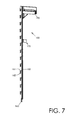
- FIG. 7 shows a perspective view of a locking assembly according to the present invention.
- FIGS. 8A , 8 B en 9 show details of the locking assembly of FIG. 7 ;
- FIGS. 10A and 10B illustrate an extrusion plate of the door.
- FIGS. 1A and 1B show perspective views of a cart according to the present invention, generally indicated by reference numeral 1 .
- the cart 1 is suitable for use in aisles of airplanes, although other applications are also conceivable, for instance in aisles of trains or buses.
- the cart has a relatively small width B that is sufficiently smaller than the aisle width concerned.
- the height of the cart is typically in the order of about 1 m.
- the length of the cart is indicated by L.
- the cart has a cabinet-shaped body 10 , with a bottom 11 , an upper wall 12 with thereon a dish 60 with an upstanding edge 61 and a handle 62 , and side walls 13 , enclosing an inner space 16 .
- Wheels 14 are mounted below the bottom 11 .
- the cart has a door 20 .
- a door may also be present at the rear side (not visible in FIGS. 1A-1B ), a fixedly closed rear wall may also be present here.
- FIG. 1C is a view comparable to FIG. 1B , with the door 20 being left away. It can be seen in this figure that the cabinet-shaped body 10 at its front is provided with a door frame 30 for mounting thereto the door 20 .
- the door frame 30 may be a solid plastic form piece, or possibly a metal form piece such as an aluminum form piece.
- the cabinet-shaped body 10 is formed as an extrusion part from plastic, preferably PEI or PPSU, but the present invention is not limited to application of these materials.
- the door 20 comprises a plastic door body 21 with two vertical side edges 22 , 23 . Along the entire length of one of the vertical side edges, the righthand side edge 22 in the embodiment shown, the door 20 is provided with a double action multipoint piano hinge 40 with which the door 20 is attached to the frame 30 .
- FIG. 2 shows an enlargement of part II of FIG. 1B , in which this double action piano hinge 40 can be seen more clearly.
- FIG. 3 shows, the double action piano hinge 40 in taken apart condition.
- FIG. 4 shows a cross section of the edge part 22 of the door 20 .
- the piano hinge 40 comprises a first hinge part 41 , an intermediate hinge part 42 , and a third hinge part 43 .
- the first hinge part 41 comprises an elongate strip 44 that at one longitudinal side is provided with a series of mutually aligned eyes 45 above each other. In the example shown, the number of eyes 45 is equal to 13, but this number may be higher or lower.
- the elongate strip 44 is attached to the door body 21 . At least along its side edge 22 , the door body 21 has a thickness larger than the thickness of the elongate strip 44 , and is provided with a recess in which the elongate strip 44 fits.
- the door body 21 comprises two shell parts 24 and 25 attached to each other or to a carrier body (not shown), wherein the elongate strip 44 is accommodated between the edge parts of these shell parts 24 and 25 , as shown in FIG. 4 .
- the first hinge part 41 may be manufactured from plastic, but may also be manufactured from metal such as aluminum. Alternatively, the first hinge part 41 may be formed as integral part of the door body 21 , in which case the elongate strip 44 may be omitted.
- the intermediate hinge part 42 comprises an elongate strip 46 that at one longitudinal side is provided with a first series of mutually aligned eyes 47 above each other and at its opposite longitudinal side is provided with a second series of mutually aligned eyes 48 above each other.
- the first eyes 47 and the second eyes 48 are displaced with respect to each other, so that the second eyes 48 are aligned with first interspaces 51 between the first eyes 47 while the first eyes 47 are aligned with second interspaces 52 between the second eyes 48 .
- the first eyes 47 have a length equal to the interspaces 53 between the eyes 45 of the first hinge part 44
- the eyes 45 of the first hinge part 44 have a length equal to the first interspaces 51 between the first eyes 47 .
- a first hinge pin 61 couples the first hinge part 41 with the intermediate hinge part 42 . It can be seen in FIG. 1B that the intermediate hinge part 42 has a lowermost first eye 47 below the lowermost eye 45 of the first hinge part 41 , and an uppermost first eye 47 above the uppermost eye 45 of the first hinge part 41 , so that the number of first eyes 47 is equal to 14 while the number of second eyes 48 is equal to 13.
- the third hinge part 43 comprises a series of mutually aligned eyes 49 attached above each other at the front side of the door frame 30 , with mutual interspaces 54 .
- the third hinge part 43 may comprise a separate strip carrying the eyes and attached to the frame, but preferably and as shown the eyes 49 are formed integrally with the frame 30 .
- the eyes 49 have a length equal to the second interspaces 52 between the second eyes 48 of the intermediate hinge part 42 , while the second eyes 48 of the intermediate hinge part 42 have a length equal to the interspaces 54 between the eyes 49 of the second hinge part 43 .
- a second hinge pin 62 ( FIG. 4 ) couples the third hinge part 43 with the intermediate hinge part 42 .
- the third hinge part 43 comprises an uppermost eye above the uppermost second eye 48 of the intermediate hinge part 42 and comprises a lowermost eye below the lowermost second eye 48 of the intermediate hinge part 42 , so that the number of eyes 49 is equal to 14.
- the second hinge pin 62 is longer than the intermediate hinge part 42 , and extends into the uppermost and lowermost eyes of the third hinge part 43 .
- the door body 21 together with the first hinge part 41 is capable of hinging with respect to the second hinge part 42 around the first hinge pin 61
- the second hinge part 42 is capable of hinging with respect to the door frame 30 around the second hinge pin 62 .
- the hinge assembly does not extend beyond the side face 13 of the cart, as schematically illustrated in FIG. 5A .
- the door 20 may be opened over 270.degree. in order to lie against the side, face 13 of the cart, as schematically illustrated in FIG. 5B ; in this situation, the door does not form any hindrance for placing trays or plates into the cart or removing them from the cart.
- an important aspect of this construction is that the door 20 is coupled to the cart body over its entire height so that the door remains well closed even in the case of large forces directed from inside to outside.
- the cart 1 is further provided with a multipoint lock system 100 with which the free vertical side edge of the door body 21 opposite the hinge 40 , thus the left side edge 23 in the embodiment shown, can be connected to the cart body, more particularly to the frame 30 .
- the multipoint lock system 100 comprises a series of lock eyes 110 above each other, fixed with respect to the frame 30 .
- These lock eyes 110 may be fixed to the frame 30 separately or by means of a common carrier, but preferably and as shown, the lock eyes 110 are formed integrally with the frame 30 .
- FIG. 6A is a perspective view of the cart, showing the frame 30 with the lock eyes 110 in a larger scale.
- FIG. 6B is a partial enlargement of part B in FIG. 6A
- FIG. 6C is a partial enlargement of the part B in which the frame 30 is omitted.
- each side wall 13 of the body 10 is, on its inner surface directed to the interior 16 , provided with a number of horizontal guide rails 17 , projecting towards the interior 16 , on which the edges of such plates can rest. These guide rails 17 are visible in FIG. 10 . In the embodiment shown, the number of guide rails 17 is equal to 13.
- the cart 1 according to the present invention does not have these disadvantages because at least the side wall 13 is formed as an extrusion part and because the guide rails 17 have been formed together therewith as an integral part of the side wall 13 during the extrusion process. This is clearly visible in FIG. 1C . Thus, seams and cracks can be entirely avoided, which increases the hygiene of the cart and reduces the costs for cleaning.
- the guide rails 17 are hollow, as also shown. In the preferred embodiment shown, each guide rail 17 has a triangular contour with horizontal carrier face 18 and an oblique support 19 .
- the lock eyes 110 are located at an arbitrary height. However, it is desirable that the lock eyes 110 remain within the profile of the side wall 13 . If the lock eyes 110 would project beyond the side wall 13 at the outer side of the cart, they are very vulnerable, they can damage or cause injuries, and they increase the effective width of the cart in a storage recess. If the lock eyes 110 would project beyond the side wall 13 in the inner space 16 , they hinder the plates being slid in and out and the objects standing on the plates may hook behind the lock eyes 110 .
- the lock eyes 110 can remain within the profile of the side wall 13 only if the horizontal size of the lock eyes 110 is smaller than the thickness of the side wall 13 , as measured between the planar outer wall and the planar inner wall parts between the guide rails 17 .
- Such limitation of the horizontal dimensions puts limitations on the strength of the lock eyes.
- each lock eye 110 is preferably, and as clearly visible in FIGS. 6A and 6B , aligned with respective guide rails 17 .
- each lock eye 110 has the shape of a substantially horizontal strip 111 with a vertical hole 112 , wherein the outer contour of this strip 111 , in front view, corresponds to (at least does not project outside) the outer contour of the guide rail 17 .
- the strip 111 may be rounded and may be provided with an oblique run in face 113 .
- the upper surface 114 of the strip 111 lies at the same height as the upper surface 118 of the guide rail 17 .
- the strip 111 may at its rear side be provided with an extension piece 115 fitting in the hollow rail 17 .
- FIG. 6D is a view comparable to FIG. 6C of a lower part of the cart, showing the lower left corner of the frame 30 . It can be seen in this figure that the cart has a lowermost guide rail 17 at a short distance above its bottom, but a lock eye aligned with this would be located in the bent corner part of the frame 30 . Instead thereof, a recess 120 is formed in the lowermost part of the frame 30 , in which a lock pin fits as will be discussed later. This recess is displaced in horizontal direction (in frontal view: to the right) with respect to the holes 112 aligned with each other. It is further noted that it is not essential that the holes 112 are mutually aligned.
- the lock system 100 comprises a lock assembly 150 incorporated in the door body 21 , of which FIG. 7 shows a perspective view.
- the lock assembly 150 comprises an elongate, vertically directed pin carrier 160 .
- the pin carrier 160 carries a plurality of lock pins 162 directed vertically downwards, wherein each lock pin 162 is connected to the pin carrier 160 through a lock pin arm 161 .
- the mutual distance between the lock pins corresponds to the mutual distance between the lock eyes 110 .
- the pin carrier 160 carries another lock pin 163 .
- Each pin 162 , 163 may be formed separately and may be attached separately to the carrier 160 , but it is preferred that the combination of carrier 160 , arms 161 , pins 162 and pin 163 is formed as an integral component.
- the pin carrier 160 is vertically shiftable in the door body 121 between a lower extreme position and an upper extreme position. In the upper extreme position, the lock pins 162 are located between the lock eyes 110 in vertical direction: the door can now freely hinge in order to be opened and closed. If the door is closed, each lock pin 162 , 163 is located precisely above a lock eye 110 or lock recess 120 , respectively. If the pin carrier 160 is now shifted downwards to its lower extreme position, the lock pins 162 penetrate the corresponding lock eyes 110 : the door is now bolted.
- the free side edge 23 of the door body 21 in the bolted condition is mechanically coupled to the door frame 30 at a relatively large number of places (in this example: 14).
- the lock assembly 150 comprises a safety lip 170 attached to the pin carrier 160 at a central position.
- the safety lip 170 in top view has an L-shaped contour, and comprises a leg part 171 and a foot part 172 directed substantially perpendicular to the leg part.
- the safety lip 170 is implemented as a planar strip with a bent end defining the foot part, as can clearly be seen in FIG. 8A .
- the free end of the leg part 171 is connected to the pin carrier 160 (or forms a whole herewith).
- the planar leg part 171 is directed substantially parallel to the door body 21 .
- the planar foot part 172 is directed substantially parallel to the side wall 13 (in the case of a closed door), wherein the foot part 172 is directed forward with respect to the leg part 171 , it is to say it points away from the inner space 16 .
- an anchor plate 180 is mounted in the door body 21 , also formed as an L-shaped bent plate with a leg part 181 and a foot part 182 , wherein the foot part 182 is directed parallel to and is located at only a small distance from the foot part 172 of the safety lip 170 , as is also clearly visible in FIG. 8A .
- the positions and dimensions of the foot parts 172 and 182 are such that these foot parts project outwards from the door body 21 at the visible side (outer side of the cart).
- the door body 21 has a recessed part 26 with a bottom 27 and side walls 28 , as clearly visible in FIG. 8B , which shows a perspective view at a larger scale of the part VIII in FIG. 1A .
- the foot parts 172 and 182 project above the bottom 27 of this recessed part 26 , but have a horizontal dimension smaller than the “height” of the side walls 28 of this recessed part 26 so that they do not project beyond the front face of the door body 21 .
- Both foot part 172 and 182 are provided with at least one hole 173 , 183 , respectively.
- the foot part 172 of the safety lip 170 shifts along the foot part 182 of the anchor plate 180 .
- said holes 173 and 183 are aligned with each other, and for instance a padlock may be attached here: then, the pin carrier 160 cannot be shifted upwards, and the door cannot be opened.
- FIGS. 8A and 8B show the pin carrier 160 in its upper extreme position.
- FIG. 9 is a perspective view of the upper end of the lock assembly 150 at a larger scale, illustrating that a handle 190 is attached to or integrally formed with the upper end of the pin carrier 160 .
- the handle 190 is substantially plate-shaped, and extends in the interior of the door body 21 , parallel to this door body.
- the handle 190 is provided with a horizontal recess or opening 191 , in which the fingers of a user fit.
- FIG. 1B shows among other things that the door body 21 in its upper left corner has a window 29 through which the handle 190 is accessible.
- the handle 190 In order to open the door, a user must lift the handle 190 : the pins 162 leave the eyes 110 and the door is released. When the user lets go of the handle 190 this could shift downwards again under influence of gravity. When the door is then closed, it may visually appear that the door is closed and locked, while the lock pins 162 are not extending into the eyes 110 but are abutting the eyes 110 from the outside. This is a situation that may lead to potentially dangerous misunderstandings.
- the handle 190 is preferably, and as shown, provided with one or more holding members 192 holding the lock assembly 150 in its upper extreme position. Then, in order to close and lock the door, the user must actively displace the lock assembly 150 downwards.
- the non-locked condition of the door is visually perceivable by the handle 190 being in its upper position.
- This visual perception can be facilitated by for instance giving the part of the handle 190 below the recess 191 a red color and the part of the handle above the recess 191 a green color.
- the lock assembly 150 has two holding members 192 .
- Each holding member 192 in this example is implemented as a resilient lip with a lateral projection, cooperating with a part, for instance a recess in a contra member, fixed with respect, to the door body 21 and not shown for sake of simplicity.
- said lateral projection clicks into this recess.
- said lateral projection must be moved out of this recess, against the resilient force of the lip, which requires a threshold force.
- the holding members may be implemented in several different ways.
- the holding member 192 is also capable, of holding the lock assembly 150 in its lower extreme position.
- FIG. 10A shows a perspective front view of this extrusion plate 200 , with recesses 201 and 202 for the handle 190 and the blocking means 170 , 180 , respectively.
- FIG. 10B shows a cross section view of a part of the extrusion plate 200 according to arrow B in FIG.
- the extrusion plate 200 comprises two mutually parallel plate parts 211 , 212 that are connected to each other by means of oblique lamella 213 , 214 in a triangular connection.
- the extrusion plate 200 is enclosed in two shell parts defining the outer wall and the inner wall of the door panel, respectively, but this is not shown in this figure for sake of simplicity.
- the extrusion plate 200 is made from plastic by extrusion.
- the plastic used will typically be a thermoplast, selected to meet the demands of strength and fire safety, although it is at least in principle also possible that the plastic used has thermo hardening properties.
- a suitable use is polyetherimide (PEI) or polyphenylsulfon (PPSU), or a blend of at least one of these materials, but the present invention is not limited to applying these materials.
- the favorable insights of the present invention can also be applied to stationary cabinets without wheels.
Abstract
Description
Claims (25)
Applications Claiming Priority (3)
| Application Number | Priority Date | Filing Date | Title |
|---|---|---|---|
| NL1035220A NL1035220C2 (en) | 2008-03-28 | 2008-03-28 | Trolley. |
| NL1035220 | 2008-03-28 | ||
| PCT/NL2009/000071 WO2009120067A2 (en) | 2008-03-28 | 2009-03-27 | Trolley |
Publications (2)
| Publication Number | Publication Date |
|---|---|
| US20110025006A1 US20110025006A1 (en) | 2011-02-03 |
| US8360447B2 true US8360447B2 (en) | 2013-01-29 |
Family
ID=40042970
Family Applications (1)
| Application Number | Title | Priority Date | Filing Date |
|---|---|---|---|
| US12/935,267 Active 2029-03-29 US8360447B2 (en) | 2008-03-28 | 2009-03-27 | Airline cart |
Country Status (5)
| Country | Link |
|---|---|
| US (1) | US8360447B2 (en) |
| EP (1) | EP2312973B1 (en) |
| CN (1) | CN102046042A (en) |
| NL (1) | NL1035220C2 (en) |
| WO (1) | WO2009120067A2 (en) |
Cited By (11)
| Publication number | Priority date | Publication date | Assignee | Title |
|---|---|---|---|---|
| US8864183B1 (en) * | 2011-07-27 | 2014-10-21 | Cisco Technology, Inc. | Mechanism to latch a cover closed |
| US8936260B2 (en) * | 2012-07-20 | 2015-01-20 | B/E Aerospace, Inc. | Meal cart for an aircraft galley |
| US20150225085A1 (en) * | 2005-03-04 | 2015-08-13 | Driessen Aerospace Group N.V. | Device for accomodating trolley, method for manufacturing a trolley as transport means |
| US9114748B1 (en) * | 2014-08-01 | 2015-08-25 | Otg Experience, Llc | Transportable modular system for dispensing and boxing food and beverage items |
| US9126613B2 (en) * | 2014-01-09 | 2015-09-08 | Carter Hoffmann, Inc. | Movable cart |
| US20150282615A1 (en) * | 2014-04-08 | 2015-10-08 | J&J Snack Foods Corp. | Storage and transport cart with latch |
| US20170084103A1 (en) * | 2015-09-18 | 2017-03-23 | Geerpres, Inc. | Utility cart with electronic lock cabinet |
| US9669930B2 (en) * | 2015-04-01 | 2017-06-06 | Norduyn Inc. | Galley cart with multi-capacity support |
| US10029718B2 (en) * | 2015-05-15 | 2018-07-24 | Carlisle Foodservice Products, Llc | Modular cart |
| US20190211618A1 (en) * | 2018-01-09 | 2019-07-11 | Fengyu Yu | Anti-Theft and Prying-Resistant Door |
| US10507921B2 (en) | 2017-11-15 | 2019-12-17 | Southwest Airlines Co. | Provisioning cart for on-aircraft restocking |
Families Citing this family (22)
| Publication number | Priority date | Publication date | Assignee | Title |
|---|---|---|---|---|
| NL1035220C2 (en) * | 2008-03-28 | 2009-09-29 | Aerocat B V | Trolley. |
| CN102131990B (en) * | 2008-06-27 | 2013-12-25 | 梅特罗工业有限公司 | Improved sealing structure for sealing multiple sections and drawer of medical emergency cart |
| US8465030B2 (en) * | 2008-12-07 | 2013-06-18 | Norduyn Inc. | Modular utility cart |
| CA2736656C (en) | 2010-04-11 | 2019-03-05 | Norduyn Inc. | Parts securing mechanism and method thereof |
| US20130199402A1 (en) * | 2010-04-19 | 2013-08-08 | P.A. Mohammed Ansar | Inflight catering apparatus |
| GB2480370B (en) | 2010-05-14 | 2017-03-29 | Norduyn Inc | Body reinforcement and method of manufacturing thereof |
| JP5651785B2 (en) * | 2010-09-23 | 2015-01-14 | ビーイー・エアロスペース・インコーポレーテッド | Modular integrated galley |
| EP2676880B1 (en) | 2012-06-18 | 2018-05-02 | Airbus Operations GmbH | On-board passive protection device |
| FR3013952B1 (en) * | 2013-11-29 | 2016-08-05 | Uleotech | SECURED OPENING GOODS TRANSPORT TROLLEY, SECURE OPENING / SECURING SYSTEM AND METHOD USING SUCH TROLLEY. |
| GB201406051D0 (en) * | 2014-04-03 | 2014-05-21 | Competitive Carbon Composites Ltd | Aircraft galley Cart |
| US10005482B2 (en) | 2015-11-18 | 2018-06-26 | The Boeing Company | Cart apparatus and methods for use |
| CN107327235A (en) * | 2016-04-28 | 2017-11-07 | 苏州鹭翔航空设备有限公司 | A kind of door lock mechanism |
| US10273006B2 (en) * | 2016-09-30 | 2019-04-30 | Airbus Operations Gmbh | Trolley, waste module and system for collecting waste |
| FI127110B (en) * | 2016-11-02 | 2017-11-15 | Hartwall K Oy Ab | Door, closing system and log cabinet |
| US10597158B2 (en) * | 2017-08-02 | 2020-03-24 | Panasonic Avionics Corporation | Device for use in vehicle |
| EP3774526B1 (en) * | 2018-03-28 | 2022-11-23 | Hartwell Corporation | Door assembly comprising hinge with two pins |
| USD923276S1 (en) * | 2018-04-05 | 2021-06-22 | Safran Cabin Netherlands N.v. | Trolley |
| CN109278832A (en) * | 2018-10-18 | 2019-01-29 | 江苏航空职业技术学院 | A kind of robot brain is loaded into meal cart |
| KR102153961B1 (en) * | 2019-01-31 | 2020-09-09 | 이광현 | Aviation trolley cart |
| USD903967S1 (en) * | 2019-03-29 | 2020-12-01 | Essentium Inc | Filament cart |
| CN110281830B (en) * | 2019-07-02 | 2020-03-20 | 温州兴升环保科技有限公司 | Mobile dining car equipped in high-speed public transport equipment |
| CN112325118A (en) * | 2020-10-30 | 2021-02-05 | 联想(北京)有限公司 | Supporting device and electronic equipment |
Citations (65)
| Publication number | Priority date | Publication date | Assignee | Title |
|---|---|---|---|---|
| US939287A (en) * | 1909-03-25 | 1909-11-09 | Henry L Miner | Box. |
| US1438547A (en) * | 1921-09-26 | 1922-12-12 | Lyon Metallic Mfg Company | Locker |
| US1602762A (en) * | 1925-10-28 | 1926-10-12 | Aurora Steel Products Company | Door latch |
| US1625145A (en) * | 1925-11-18 | 1927-04-19 | Lyon Metallic Mfg Company | Locker latch |
| US1771041A (en) * | 1930-05-13 | 1930-07-22 | Arthur I Epton | Door mounting |
| US1970267A (en) * | 1930-05-08 | 1934-08-14 | Lyon Metal Products Inc | Locker |
| US2337948A (en) * | 1940-07-26 | 1943-12-28 | Chicago Metal Mfg Co | Door hinge |
| US2946640A (en) * | 1954-07-30 | 1960-07-26 | Aurora Equipment Co | Locker handle construction |
| US2967080A (en) * | 1958-07-08 | 1961-01-03 | United Aircraft Corp | File cabinet locking device |
| US3216483A (en) * | 1962-03-19 | 1965-11-09 | Int Paper Co | Temporary door |
| US3321258A (en) * | 1967-05-23 | Cart for transporting food trays and the like | ||
| US3726535A (en) * | 1970-07-15 | 1973-04-10 | G Longato | Multi-purpose article of furniture |
| US3909091A (en) * | 1973-09-07 | 1975-09-30 | Gen Bathroom Products Corp | Means for temporarily hanging a cabinet on a wall surface prior to permanent attachment of said cabinet |
| US3933383A (en) * | 1974-09-20 | 1976-01-20 | Brooks Walker | Latch |
| US3977689A (en) * | 1975-02-25 | 1976-08-31 | The Cornelius Company | Nestable cart |
| US4098424A (en) * | 1976-09-29 | 1978-07-04 | Lermer Gmbh | Transport container |
| US4263853A (en) * | 1979-01-15 | 1981-04-28 | Portec, Inc. | Rail car end door positioning keeper assembly |
| US4576425A (en) * | 1984-03-05 | 1986-03-18 | Carter-Hoffman Corporation | Food service cart door structure |
| US4614374A (en) * | 1984-02-21 | 1986-09-30 | Lyon Metal Products, Incorporated | Recessed latch housing |
| US4770476A (en) * | 1987-06-05 | 1988-09-13 | Lakso Matthew L | Multiple drawer locking system |
| USD305822S (en) * | 1987-09-17 | 1990-01-30 | Intermetro Industries Corporation | Insulated food transporting cabinet |
| US4936377A (en) * | 1986-12-11 | 1990-06-26 | The Boeing Company | Food storage cart with thermo wall |
| US5000494A (en) * | 1990-04-18 | 1991-03-19 | Robert Guibleo | Recessed door handle |
| US5056194A (en) * | 1988-02-26 | 1991-10-15 | Romay Ag | Hinge for use in serving carts and the like |
| USRE34171E (en) * | 1985-01-14 | 1993-02-02 | Medication carts and cassettes | |
| US5205628A (en) * | 1990-05-10 | 1993-04-27 | Herman Miller, Inc. | Pharmaceutical cabinet locking arrangement |
| US5235833A (en) * | 1990-03-08 | 1993-08-17 | Air Inter Lignes Aeriennes Interieures | Lockable lock for drink distributing trolleys in aircraft |
| US5314244A (en) * | 1990-05-10 | 1994-05-24 | Herman Miller, Inc. | Pharmaceutical cabinet locking arrangement |
| US5427445A (en) * | 1994-10-05 | 1995-06-27 | Quest Engineering | Drawer interlock structure |
| US5475897A (en) * | 1992-12-11 | 1995-12-19 | Mitsubishi Steel Mfg. Co., Ltd. | Car door hinge |
| US5503440A (en) * | 1993-01-26 | 1996-04-02 | Schlumberger Industries | Device for controlling the opening and closing of a plurality of doors, each giving access to an enclosure |
| US5605344A (en) * | 1994-09-14 | 1997-02-25 | Herman Miller, Inc. | Transport cart |
| US6139034A (en) * | 1998-10-13 | 2000-10-31 | Williams; William | Food service cart |
| US6234498B1 (en) * | 1997-12-05 | 2001-05-22 | Jamco Corporation | Rim member structure of service cart |
| US6357806B1 (en) * | 1998-11-13 | 2002-03-19 | Jamco Corporation | Door latch device |
| US20030001465A1 (en) * | 2001-06-29 | 2003-01-02 | Carter Glen Alan | Safety cabinet |
| US6564428B2 (en) * | 2000-01-14 | 2003-05-20 | Hoffman Enclosures, Inc. | Compound hinge |
| US20030141687A1 (en) * | 2002-01-29 | 2003-07-31 | Wixted Brian J. | Computer storage cart |
| US6739093B1 (en) * | 2001-11-14 | 2004-05-25 | Charles S. Holbert | Farm gate stop device |
| US6907830B2 (en) * | 2002-05-31 | 2005-06-21 | Diebold Self-Service Systems | Multipoint lock assembly |
| US6935661B1 (en) * | 2000-11-21 | 2005-08-30 | Hewlett-Packard Development Company, L.P. | Access panel latching system |
| US20050218615A1 (en) * | 2004-03-31 | 2005-10-06 | Hu Ben P | Aircraft galley carts and associated methods of manufacture |
| US6971322B2 (en) * | 2003-03-14 | 2005-12-06 | Delaware Capital Formation Inc. | Protective enclosure |
| US20050285360A1 (en) * | 2004-06-23 | 2005-12-29 | Genpak Llc | Method for providing tamper evident system for portable carts |
| US20060070814A1 (en) * | 2004-07-22 | 2006-04-06 | Hu Ben P | Securement latches and associated aircraft galley carts and methods |
| US20060108757A1 (en) * | 2004-09-24 | 2006-05-25 | Brookmire Derek A | Catering cart having gravity-feed and counter system |
| US7370890B2 (en) * | 2000-11-07 | 2008-05-13 | Delta Consolidated Industries | Storage cabinet with locking system having dual release members |
| US7370867B2 (en) * | 2004-08-11 | 2008-05-13 | Metro Industries, Inc. | Banquet cart |
| US20080150300A1 (en) * | 2002-03-27 | 2008-06-26 | Newell Operating Company | Multipoint Lock Assembly |
| US7444830B2 (en) * | 2004-03-08 | 2008-11-04 | The Boeing Company | Aircraft galley carts and other insulated food storage units, and methods for their use |
| US20080278043A1 (en) * | 2007-05-08 | 2008-11-13 | Waterloo Industries, Inc. | Drawer lock mechanism |
| US20080276840A1 (en) * | 2005-03-04 | 2008-11-13 | Driessen Aerospace Group N.V. | Device For Accommodating Objects, as Well as Transport Means |
| US7461849B2 (en) * | 2005-12-22 | 2008-12-09 | Emiph, Llc | Method and apparatus for an electronic equipment rack |
| US7494012B1 (en) * | 2005-02-25 | 2009-02-24 | Apothecary Products, Inc. | Lockable pill container |
| US7510249B2 (en) * | 2001-05-10 | 2009-03-31 | The Mills Company Inc. | Storage unit |
| US20100140890A1 (en) * | 2008-12-07 | 2010-06-10 | Mathieu Boivin | Modular utility cart |
| US7775564B2 (en) * | 2005-08-10 | 2010-08-17 | Compumeric Engineering, Inc. | Animal-resistant latching system |
| US7856696B2 (en) * | 2008-12-11 | 2010-12-28 | Agco Corporation | Moveable boom hinge |
| US20110012371A1 (en) * | 2009-07-17 | 2011-01-20 | Scranton Products Inc. | Locker |
| US20110018285A1 (en) * | 2009-02-23 | 2011-01-27 | Endura Products, Inc. | Multi-point locking system and astragal |
| US20110025006A1 (en) * | 2008-03-28 | 2011-02-03 | Aerocat B.V. | Trolley |
| US7909419B2 (en) * | 2008-05-07 | 2011-03-22 | Spacesaver Corporation | Restricted access storage compartment |
| US20110116239A1 (en) * | 2009-11-17 | 2011-05-19 | Emerson Network Power, Energy Systems, North America, Inc. | Locking Mechanisms for Retaining Two Swinging Panels and Apparatus and Enclosures Including a Locking Mechanism for Retaining Two Swinging Panels |
| US7963533B2 (en) * | 2003-11-17 | 2011-06-21 | Wenger Corporation | All-terrain retail merchandising unit |
| US20110278879A1 (en) * | 2010-05-14 | 2011-11-17 | Belanger Martin | Body reinforcement and method of manufacturing thereof |
Family Cites Families (10)
| Publication number | Priority date | Publication date | Assignee | Title |
|---|---|---|---|---|
| NL7806543A (en) * | 1978-06-16 | 1979-12-18 | Stichting Melkverpakking | ROLL-IN CONTAINER. |
| EP0066547A3 (en) * | 1981-06-02 | 1985-10-09 | Schweizerische Aluminium Ag | Service trolley |
| CN86201179U (en) * | 1986-02-28 | 1986-12-03 | 李秉烈 | Multi-function portable hand cart |
| SE9203880L (en) * | 1992-12-22 | 1994-06-23 | Samhall Bohusgruppen Ab | Locking device for safety cabinets |
| NL1000688C2 (en) * | 1995-06-29 | 1996-12-31 | Flex Concepts B V | Serving trolley. |
| JP3049510U (en) * | 1997-12-05 | 1998-06-19 | 株式会社ジャムコ | Food truck shock absorber |
| DE19939614C1 (en) * | 1999-08-20 | 2001-09-27 | Driescher Eltech Werk | Pressure-resistant switchgear cabinet has locking bolts and locking elements securing pivoted cabinet door upon internal arcing |
| JP3478291B2 (en) * | 2002-05-13 | 2003-12-15 | 株式会社イトーキクレビオ | Wagon desk with lifting top |
| NL1028462C2 (en) * | 2005-03-04 | 2006-09-06 | Driessen Aerospace Group Nv | Trolley, method for manufacturing a trolley, and means of transport. |
| CN2819918Y (en) * | 2006-03-09 | 2006-09-27 | 黄晟 | Anti-collision hand push dining trolley |
-
2008
- 2008-03-28 NL NL1035220A patent/NL1035220C2/en not_active IP Right Cessation
-
2009
- 2009-03-27 US US12/935,267 patent/US8360447B2/en active Active
- 2009-03-27 CN CN2009801194389A patent/CN102046042A/en active Pending
- 2009-03-27 WO PCT/NL2009/000071 patent/WO2009120067A2/en active Application Filing
- 2009-03-27 EP EP20090725904 patent/EP2312973B1/en not_active Not-in-force
Patent Citations (69)
| Publication number | Priority date | Publication date | Assignee | Title |
|---|---|---|---|---|
| US3321258A (en) * | 1967-05-23 | Cart for transporting food trays and the like | ||
| US939287A (en) * | 1909-03-25 | 1909-11-09 | Henry L Miner | Box. |
| US1438547A (en) * | 1921-09-26 | 1922-12-12 | Lyon Metallic Mfg Company | Locker |
| US1602762A (en) * | 1925-10-28 | 1926-10-12 | Aurora Steel Products Company | Door latch |
| US1625145A (en) * | 1925-11-18 | 1927-04-19 | Lyon Metallic Mfg Company | Locker latch |
| US1970267A (en) * | 1930-05-08 | 1934-08-14 | Lyon Metal Products Inc | Locker |
| US1771041A (en) * | 1930-05-13 | 1930-07-22 | Arthur I Epton | Door mounting |
| US2337948A (en) * | 1940-07-26 | 1943-12-28 | Chicago Metal Mfg Co | Door hinge |
| US2946640A (en) * | 1954-07-30 | 1960-07-26 | Aurora Equipment Co | Locker handle construction |
| US2967080A (en) * | 1958-07-08 | 1961-01-03 | United Aircraft Corp | File cabinet locking device |
| US3216483A (en) * | 1962-03-19 | 1965-11-09 | Int Paper Co | Temporary door |
| US3726535A (en) * | 1970-07-15 | 1973-04-10 | G Longato | Multi-purpose article of furniture |
| US3909091A (en) * | 1973-09-07 | 1975-09-30 | Gen Bathroom Products Corp | Means for temporarily hanging a cabinet on a wall surface prior to permanent attachment of said cabinet |
| US3933383A (en) * | 1974-09-20 | 1976-01-20 | Brooks Walker | Latch |
| US3977689A (en) * | 1975-02-25 | 1976-08-31 | The Cornelius Company | Nestable cart |
| US4098424A (en) * | 1976-09-29 | 1978-07-04 | Lermer Gmbh | Transport container |
| US4263853A (en) * | 1979-01-15 | 1981-04-28 | Portec, Inc. | Rail car end door positioning keeper assembly |
| US4614374A (en) * | 1984-02-21 | 1986-09-30 | Lyon Metal Products, Incorporated | Recessed latch housing |
| US4576425A (en) * | 1984-03-05 | 1986-03-18 | Carter-Hoffman Corporation | Food service cart door structure |
| USRE34171E (en) * | 1985-01-14 | 1993-02-02 | Medication carts and cassettes | |
| US4936377A (en) * | 1986-12-11 | 1990-06-26 | The Boeing Company | Food storage cart with thermo wall |
| US4770476A (en) * | 1987-06-05 | 1988-09-13 | Lakso Matthew L | Multiple drawer locking system |
| USD305822S (en) * | 1987-09-17 | 1990-01-30 | Intermetro Industries Corporation | Insulated food transporting cabinet |
| US5056194A (en) * | 1988-02-26 | 1991-10-15 | Romay Ag | Hinge for use in serving carts and the like |
| US5235833A (en) * | 1990-03-08 | 1993-08-17 | Air Inter Lignes Aeriennes Interieures | Lockable lock for drink distributing trolleys in aircraft |
| US5000494A (en) * | 1990-04-18 | 1991-03-19 | Robert Guibleo | Recessed door handle |
| US5205628A (en) * | 1990-05-10 | 1993-04-27 | Herman Miller, Inc. | Pharmaceutical cabinet locking arrangement |
| US5314244A (en) * | 1990-05-10 | 1994-05-24 | Herman Miller, Inc. | Pharmaceutical cabinet locking arrangement |
| US5475897A (en) * | 1992-12-11 | 1995-12-19 | Mitsubishi Steel Mfg. Co., Ltd. | Car door hinge |
| US5503440A (en) * | 1993-01-26 | 1996-04-02 | Schlumberger Industries | Device for controlling the opening and closing of a plurality of doors, each giving access to an enclosure |
| US5605344A (en) * | 1994-09-14 | 1997-02-25 | Herman Miller, Inc. | Transport cart |
| US5427445A (en) * | 1994-10-05 | 1995-06-27 | Quest Engineering | Drawer interlock structure |
| US6234498B1 (en) * | 1997-12-05 | 2001-05-22 | Jamco Corporation | Rim member structure of service cart |
| US6139034A (en) * | 1998-10-13 | 2000-10-31 | Williams; William | Food service cart |
| US6357806B1 (en) * | 1998-11-13 | 2002-03-19 | Jamco Corporation | Door latch device |
| US6564428B2 (en) * | 2000-01-14 | 2003-05-20 | Hoffman Enclosures, Inc. | Compound hinge |
| US7370890B2 (en) * | 2000-11-07 | 2008-05-13 | Delta Consolidated Industries | Storage cabinet with locking system having dual release members |
| US6935661B1 (en) * | 2000-11-21 | 2005-08-30 | Hewlett-Packard Development Company, L.P. | Access panel latching system |
| US7510249B2 (en) * | 2001-05-10 | 2009-03-31 | The Mills Company Inc. | Storage unit |
| US20030001465A1 (en) * | 2001-06-29 | 2003-01-02 | Carter Glen Alan | Safety cabinet |
| US6739093B1 (en) * | 2001-11-14 | 2004-05-25 | Charles S. Holbert | Farm gate stop device |
| US20030141687A1 (en) * | 2002-01-29 | 2003-07-31 | Wixted Brian J. | Computer storage cart |
| US7055833B2 (en) * | 2002-01-29 | 2006-06-06 | Bretford Manufacturing, Inc. | Computer storage cart |
| US20080150300A1 (en) * | 2002-03-27 | 2008-06-26 | Newell Operating Company | Multipoint Lock Assembly |
| US6907830B2 (en) * | 2002-05-31 | 2005-06-21 | Diebold Self-Service Systems | Multipoint lock assembly |
| US6971322B2 (en) * | 2003-03-14 | 2005-12-06 | Delaware Capital Formation Inc. | Protective enclosure |
| US7963533B2 (en) * | 2003-11-17 | 2011-06-21 | Wenger Corporation | All-terrain retail merchandising unit |
| US7444830B2 (en) * | 2004-03-08 | 2008-11-04 | The Boeing Company | Aircraft galley carts and other insulated food storage units, and methods for their use |
| US20050218615A1 (en) * | 2004-03-31 | 2005-10-06 | Hu Ben P | Aircraft galley carts and associated methods of manufacture |
| US7544915B2 (en) * | 2004-03-31 | 2009-06-09 | The Boeing Company | Aircraft galley carts and associated methods of manufacture |
| US20050285360A1 (en) * | 2004-06-23 | 2005-12-29 | Genpak Llc | Method for providing tamper evident system for portable carts |
| US20060070814A1 (en) * | 2004-07-22 | 2006-04-06 | Hu Ben P | Securement latches and associated aircraft galley carts and methods |
| US7458441B2 (en) * | 2004-07-22 | 2008-12-02 | The Boeing Company | Securement latches and associated aircraft galley carts and methods |
| US7370867B2 (en) * | 2004-08-11 | 2008-05-13 | Metro Industries, Inc. | Banquet cart |
| US20060108757A1 (en) * | 2004-09-24 | 2006-05-25 | Brookmire Derek A | Catering cart having gravity-feed and counter system |
| US7494012B1 (en) * | 2005-02-25 | 2009-02-24 | Apothecary Products, Inc. | Lockable pill container |
| US20080276840A1 (en) * | 2005-03-04 | 2008-11-13 | Driessen Aerospace Group N.V. | Device For Accommodating Objects, as Well as Transport Means |
| US7942430B2 (en) * | 2005-03-04 | 2011-05-17 | Driessen Aerospace Group N.V. | Device for accommodating objects, as well as transport means |
| US7775564B2 (en) * | 2005-08-10 | 2010-08-17 | Compumeric Engineering, Inc. | Animal-resistant latching system |
| US7461849B2 (en) * | 2005-12-22 | 2008-12-09 | Emiph, Llc | Method and apparatus for an electronic equipment rack |
| US20080278043A1 (en) * | 2007-05-08 | 2008-11-13 | Waterloo Industries, Inc. | Drawer lock mechanism |
| US20110025006A1 (en) * | 2008-03-28 | 2011-02-03 | Aerocat B.V. | Trolley |
| US7909419B2 (en) * | 2008-05-07 | 2011-03-22 | Spacesaver Corporation | Restricted access storage compartment |
| US20100140890A1 (en) * | 2008-12-07 | 2010-06-10 | Mathieu Boivin | Modular utility cart |
| US7856696B2 (en) * | 2008-12-11 | 2010-12-28 | Agco Corporation | Moveable boom hinge |
| US20110018285A1 (en) * | 2009-02-23 | 2011-01-27 | Endura Products, Inc. | Multi-point locking system and astragal |
| US20110012371A1 (en) * | 2009-07-17 | 2011-01-20 | Scranton Products Inc. | Locker |
| US20110116239A1 (en) * | 2009-11-17 | 2011-05-19 | Emerson Network Power, Energy Systems, North America, Inc. | Locking Mechanisms for Retaining Two Swinging Panels and Apparatus and Enclosures Including a Locking Mechanism for Retaining Two Swinging Panels |
| US20110278879A1 (en) * | 2010-05-14 | 2011-11-17 | Belanger Martin | Body reinforcement and method of manufacturing thereof |
Cited By (15)
| Publication number | Priority date | Publication date | Assignee | Title |
|---|---|---|---|---|
| US20150225085A1 (en) * | 2005-03-04 | 2015-08-13 | Driessen Aerospace Group N.V. | Device for accomodating trolley, method for manufacturing a trolley as transport means |
| US8864183B1 (en) * | 2011-07-27 | 2014-10-21 | Cisco Technology, Inc. | Mechanism to latch a cover closed |
| US9193462B2 (en) | 2012-07-20 | 2015-11-24 | B/E Aerospace, Inc. | Meal cart for an aircraft galley |
| US8936260B2 (en) * | 2012-07-20 | 2015-01-20 | B/E Aerospace, Inc. | Meal cart for an aircraft galley |
| US9126613B2 (en) * | 2014-01-09 | 2015-09-08 | Carter Hoffmann, Inc. | Movable cart |
| US20150282615A1 (en) * | 2014-04-08 | 2015-10-08 | J&J Snack Foods Corp. | Storage and transport cart with latch |
| US9114748B1 (en) * | 2014-08-01 | 2015-08-25 | Otg Experience, Llc | Transportable modular system for dispensing and boxing food and beverage items |
| US9963061B2 (en) | 2014-08-01 | 2018-05-08 | Otg Experience, Llc | Transportable modular system for dispensing and boxing food and beverage items |
| US10676009B2 (en) | 2014-08-01 | 2020-06-09 | Otg Experience, Llc | Transportable modular system for dispensing and boxing food and beverage items |
| US9669930B2 (en) * | 2015-04-01 | 2017-06-06 | Norduyn Inc. | Galley cart with multi-capacity support |
| US10029718B2 (en) * | 2015-05-15 | 2018-07-24 | Carlisle Foodservice Products, Llc | Modular cart |
| US20170084103A1 (en) * | 2015-09-18 | 2017-03-23 | Geerpres, Inc. | Utility cart with electronic lock cabinet |
| US9741189B2 (en) * | 2015-09-18 | 2017-08-22 | Geerpres, Inc. | Utility cart with electronic lock cabinet |
| US10507921B2 (en) | 2017-11-15 | 2019-12-17 | Southwest Airlines Co. | Provisioning cart for on-aircraft restocking |
| US20190211618A1 (en) * | 2018-01-09 | 2019-07-11 | Fengyu Yu | Anti-Theft and Prying-Resistant Door |
Also Published As
| Publication number | Publication date |
|---|---|
| WO2009120067A2 (en) | 2009-10-01 |
| EP2312973B1 (en) | 2012-10-31 |
| US20110025006A1 (en) | 2011-02-03 |
| WO2009120067A3 (en) | 2010-07-29 |
| CN102046042A (en) | 2011-05-04 |
| NL1035220C2 (en) | 2009-09-29 |
| EP2312973A2 (en) | 2011-04-27 |
Similar Documents
| Publication | Publication Date | Title |
|---|---|---|
| US8360447B2 (en) | Airline cart | |
| US10314196B2 (en) | Reinforced server sliding rail mounting structure | |
| US9878649B2 (en) | High density foldaway shelving | |
| US20080272676A1 (en) | Boltless cabinet assembly | |
| US20110006496A1 (en) | Trolley | |
| US20150108303A1 (en) | Adaptable u-shaped bracket assemblies for a load stop pallet rack system | |
| EP2841670B1 (en) | Device for accommodating objects and transportation means comprising such a device | |
| EP0922415B1 (en) | Rim member structure of service cart | |
| EP2405218B1 (en) | Refrigerator and small part container therefore | |
| US8025148B2 (en) | Stackable roll containers | |
| JP5961782B2 (en) | Fall prevention storage box | |
| JP5818286B1 (en) | Fall prevention storage box | |
| DE20209130U1 (en) | Box-shaped cabinet furniture for modular construction of office furniture | |
| KR101283236B1 (en) | Food carrier bag | |
| EP3418241B1 (en) | An elevator car | |
| CN111227540A (en) | Multi-door anti-theft storage cabinet | |
| WO2012033400A1 (en) | Service drawer for a trolley and a trolley | |
| CN216364315U (en) | Novel guide rail device and kitchen high cabinet | |
| US9849986B2 (en) | Aircraft galley unit | |
| CN211933292U (en) | Multi-door anti-theft storage cabinet | |
| GB2415887A (en) | Curtain rail assembly | |
| CN214760080U (en) | Plastic drawer and storage cabinet with same | |
| CN215076769U (en) | Concealed opening domestic drawer cabinet | |
| CN213488074U (en) | Anti-collision device of intelligent logistics warehouse shelf | |
| CN210383262U (en) | Anti-toppling cabinet |
Legal Events
| Date | Code | Title | Description |
|---|---|---|---|
| AS | Assignment |
Owner name: AEROCAT B.V., NETHERLANDS Free format text: ASSIGNMENT OF ASSIGNORS INTEREST;ASSIGNOR:KNOPPERS, GERMAN ENRIQUE;REEL/FRAME:025240/0731 Effective date: 20090624 |
|
| STCF | Information on status: patent grant |
Free format text: PATENTED CASE |
|
| FPAY | Fee payment |
Year of fee payment: 4 |
|
| MAFP | Maintenance fee payment |
Free format text: PAYMENT OF MAINTENANCE FEE, 8TH YR, SMALL ENTITY (ORIGINAL EVENT CODE: M2552); ENTITY STATUS OF PATENT OWNER: SMALL ENTITY Year of fee payment: 8 |
|
| AS | Assignment |
Owner name: COOEPERATIEVE RABOBANK U.A., NETHERLANDS Free format text: ASSIGNMENT OF ASSIGNORS INTEREST;ASSIGNOR:AEROCAT B.V.;REEL/FRAME:063805/0172 Effective date: 20210419 |
|
| AS | Assignment |
Owner name: VDL FIBERTECH INDUSTRIES B.V., NETHERLANDS Free format text: ASSIGNMENT OF ASSIGNORS INTEREST;ASSIGNOR:COOEPERATIEVE RABOBANK U.A.;REEL/FRAME:063836/0672 Effective date: 20230404 |