US8345120B2 - Electronic camera with self-adjusting flash and image-capture sensitivity - Google Patents
Electronic camera with self-adjusting flash and image-capture sensitivity Download PDFInfo
- Publication number
- US8345120B2 US8345120B2 US11/082,065 US8206505A US8345120B2 US 8345120 B2 US8345120 B2 US 8345120B2 US 8206505 A US8206505 A US 8206505A US 8345120 B2 US8345120 B2 US 8345120B2
- Authority
- US
- United States
- Prior art keywords
- image
- arithmetic operation
- operation circuit
- capturing
- flash
- Prior art date
- Legal status (The legal status is an assumption and is not a legal conclusion. Google has not performed a legal analysis and makes no representation as to the accuracy of the status listed.)
- Active, expires
Links
- 230000035945 sensitivity Effects 0.000 title claims abstract description 302
- 238000001514 detection method Methods 0.000 claims abstract description 62
- 238000012545 processing Methods 0.000 description 265
- 238000012937 correction Methods 0.000 description 55
- 238000004891 communication Methods 0.000 description 37
- 230000008859 change Effects 0.000 description 29
- 230000004044 response Effects 0.000 description 20
- 230000006870 function Effects 0.000 description 15
- 238000006243 chemical reaction Methods 0.000 description 11
- 230000000694 effects Effects 0.000 description 7
- 230000008901 benefit Effects 0.000 description 4
- 238000010586 diagram Methods 0.000 description 4
- APTZNLHMIGJTEW-UHFFFAOYSA-N pyraflufen-ethyl Chemical compound C1=C(Cl)C(OCC(=O)OCC)=CC(C=2C(=C(OC(F)F)N(C)N=2)Cl)=C1F APTZNLHMIGJTEW-UHFFFAOYSA-N 0.000 description 4
- 230000006835 compression Effects 0.000 description 3
- 238000007906 compression Methods 0.000 description 3
- 230000010354 integration Effects 0.000 description 3
- 230000001360 synchronised effect Effects 0.000 description 3
- 230000006837 decompression Effects 0.000 description 2
- 230000003247 decreasing effect Effects 0.000 description 2
- 230000007246 mechanism Effects 0.000 description 2
- 230000003287 optical effect Effects 0.000 description 2
- 230000002441 reversible effect Effects 0.000 description 2
- 230000002459 sustained effect Effects 0.000 description 2
- 230000007812 deficiency Effects 0.000 description 1
- 238000013461 design Methods 0.000 description 1
- 230000005713 exacerbation Effects 0.000 description 1
- 238000010348 incorporation Methods 0.000 description 1
- 238000012986 modification Methods 0.000 description 1
- 230000004048 modification Effects 0.000 description 1
- 238000010926 purge Methods 0.000 description 1
- 229910052709 silver Inorganic materials 0.000 description 1
- 239000004332 silver Substances 0.000 description 1
- -1 silver halide Chemical class 0.000 description 1
- 238000012360 testing method Methods 0.000 description 1
- 238000012546 transfer Methods 0.000 description 1
Images


Classifications
-
- H—ELECTRICITY
- H04—ELECTRIC COMMUNICATION TECHNIQUE
- H04N—PICTORIAL COMMUNICATION, e.g. TELEVISION
- H04N23/00—Cameras or camera modules comprising electronic image sensors; Control thereof
- H04N23/70—Circuitry for compensating brightness variation in the scene
-
- H—ELECTRICITY
- H04—ELECTRIC COMMUNICATION TECHNIQUE
- H04N—PICTORIAL COMMUNICATION, e.g. TELEVISION
- H04N23/00—Cameras or camera modules comprising electronic image sensors; Control thereof
- H04N23/70—Circuitry for compensating brightness variation in the scene
- H04N23/72—Combination of two or more compensation controls
Definitions
- the present invention relates to an electronic camera that captures a subject image by using an image-capturing device.
- An apex calculation known in the related art is executed to calculate the optimal exposure quantity to be achieved in a camera as expressed in (1) below by using an aperture value AV of the photographic lens, a shutter speed (exposure period) TV, a subject brightness BV and an exposure sensitivity SV.
- the aperture value AV and the shutter speed TV are calculated in correspondence to the subject brightness BV so as to achieve the optimal exposure.
- the aperture value AV, the shutter speed TV and the image-capturing sensitivity SV can be determined in correspondence to the subject brightness BV as long as the gain at the image-capturing device, i.e., the exposure sensitivity (image-capturing sensitivity) SV is variable.
- the brightness level of a main subject is often low if the main subject needs to be illuminated with flash light emitted from an illuminating device during a photographing operation.
- the image-capturing sensitivity SV is adjusted to a higher level through the exposure calculation expressed as in (1) above.
- the main subject may be overexposed if it is illuminated with flash light from the illuminating device after the image-capturing sensitivity SV is adjusted as described above.
- the image portion other than the main subject, such as the background may be overexposed even if the main subject is exposed to the correct extent.
- an electronic camera comprises: an image-capturing unit with variable image-capturing sensitivity, which captures an image of a subject through a photographic lens; a brightness detection unit that detects subject brightness; an exposure calculation unit that executes an exposure calculation by using, at least, the image-capturing sensitivity set at the image-capturing unit and the subject brightness having been detected; a flash quantity calculation unit that calculates a main flash quantity for a flash unit that illuminates the subject when capturing an image thereof; and a sensitivity adjusting unit that adjusts the image-capturing sensitivity so as to achieve optimal exposure with a main flash quantity within a flash quantity control range of the flash unit when the main flash quantity having been calculated by the flash quantity calculation unit is outside the flash quantity control range, and if the image-capturing sensitivity has been adjusted by the sensitivity adjusting unit, the exposure calculation unit re-executes the exposure calculation.
- the electronic camera in the 1st aspect, it is preferred that: there is further provided a reflected light detection unit that detects reflected light from the subject when the flash unit executes a preliminary flash emission; and the flash quantity calculation unit calculates the main flash quantity needed for an image-capturing operation based upon a detection signal obtained at the reflected light detection unit in the preliminary flash emission and the image-capturing sensitivity currently set at the image-capturing unit.
- the exposure calculation unit alters an exposure time period which is currently set when the exposure calculation is re-executed.
- the exposure calculation unit does not re-execute the exposure calculation if the camera is set in a shutter speed priority automatic exposure calculation mode.
- the exposure calculation unit does not re-execute the exposure calculation if the camera is set in a manual exposure mode.
- the exposure calculation unit when re-executing the exposure calculation, adjusts at least one of an aperture value and a shutter speed set in the camera if the camera is set in a program automatic exposure calculation mode, adjusts the aperture value if the camera is set in a shutter speed priority automatic exposure calculation mode and adjusts the shutter speed if the camera is set in an aperture priority automatic exposure calculation mode; and the exposure calculation unit does not re-execute the exposure calculation if the camera is set in a manual exposure mode.
- an electronic camera comprises: an image-capturing device that captures a subject image through a photographic lens; a brightness detection unit that detects subject brightness; a first exposure calculation unit that executes an exposure calculation by using at least an exposure sensitivity currently set for the image-capturing device and the subject brightness having been detected among the exposure sensitivity currently set for the image-capturing device, an exposure time length currently set for the image-capturing device, an currently set aperture value and the detected subject brightness; a reflected light detection unit that detects reflected light from the main subject when light is emitted from a flash emitting unit which executes a main flash emission to illuminate the subject during a photographing operation and a preliminary flash emission to illuminate the subject prior to the photographing operation; a flash quantity calculation unit that calculates a main flash quantity which needs to be achieved for the photographing operation based upon a detection signal obtained at the reflected light detection unit during the preliminary flash emission and the exposure sensitivity; a sensitivity adjusting unit that adjusts the currently set exposure sensitivity to an exposure sensitivity needed to
- an electronic camera comprises: an image-capturing unit with variable image-capturing sensitivity, which captures an image of a subject through a photographic lens; a brightness detection unit that detects a subject brightness; a first calculation unit that calculates an ambient light over/under extent by using an image-capturing sensitivity set for the image-capturing unit, an exposure time length set for an image-capturing operation, an aperture value set for the image-capturing operation and the subject brightness having been detected; a second calculation unit that calculates a main flash quantity to be achieved at a flash unit which illuminates the subject during the image-capturing operation; a third calculation unit that calculates a correction quantity indicating an extent by which the currently set image-capturing sensitivity should be corrected so as to achieve optimal exposure of the subject with a main flash quantity within a variable flash quantity range if the main flash quantity having been calculated by the second calculation unit is outside the variable flash quantity range of the flash unit; and a sensitivity adjusting unit that adjusts the currently set image-capturing sensitivity based upon the correction quantity having been calculated
- the electronic camera in the electronic camera according to the 8th aspect, it is preferred that: there is further provided a reflected light detection unit that detects reflected light from the subject when the flash unit executes a preliminary flash emission; and the second calculation unit calculates the main flash quantity needed for an image-capturing operation based upon a detection signal obtained at the reflected light detection unit during the preliminary flash emission and the image-capturing sensitivity currently set for the image-capturing unit.
- the sensitivity adjusting unit adjusts the image-capturing sensitivity by restricting an extent of change in the image-capturing sensitivity in correspondence to the ambient light over/under extent.
- the sensitivity adjusting unit does not alter the image-capturing sensitivity.
- the sensitivity adjusting unit adjusts the image-capturing sensitivity based upon the ambient light over/under extent.
- the sensitivity adjusting unit adjusts the image-capturing sensitivity based upon the correction quantity.
- the second calculation unit corrects the main flash quantity in correspondence to a flash control correction quantity currently set at the camera; and the third calculation unit corrects the correction quantity in correspondence to the currently set flash control correction quantity.
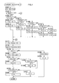
- FIG. 1 is a block diagram of the structure adopted in the electronic camera achieved in a first embodiment of the present invention
- FIG. 2 presents a flowchart of the camera operation processing
- FIG. 3 presents a flowchart of the camera operation processing
- FIG. 4 presents a flowchart of the camera operation processing
- FIG. 5 presents a detailed flowchart of the setting processing
- FIG. 6 presents a detailed flowchart of the communication processing
- FIG. 7 presents a detailed flowchart of the exposure calculation processing A
- FIG. 8 presents a detailed flowchart of the exposure calculation processing A
- FIG. 9 presents a detailed flowchart of the display processing
- FIG. 10 presents a detailed flowchart of the image-capturing sequence processing A
- FIG. 11 presents a detailed flowchart of the exposure calculation processing B executed when a flash unit is utilized
- FIG. 12 presents a detailed flowchart of the image-capturing sequence processing B
- FIG. 13 presents a detailed flowchart of the image-capturing sequence processing B
- FIG. 14 presents a detailed flowchart of the image-capturing sequence processing B
- FIG. 15 presents a detailed flowchart of the image-capturing sequence processing B
- FIG. 16 presents a detailed flowchart of the image-capturing sequence processing C
- FIG. 17 presents a detailed flowchart of the image-capturing sequence processing C
- FIG. 18 presents a detailed flowchart of the image-capturing sequence processing C
- FIG. 19 presents a detailed flowchart of the image-capturing sequence processing C
- FIG. 20 presents a detailed flowchart of the exposure calculation processing BB
- FIG. 21 is a program chart representing the operation executed when neither flash unit is utilized.
- FIG. 22 is a program chart representing the operation executed when a flash unit is utilized
- FIG. 23 presents a detailed flowchart of the exposure calculation processing BB 1 in a second embodiment
- FIG. 24 presents a detailed flowchart of the exposure calculation processing BB 2 ;
- FIG. 25 presents a detailed flowchart of the exposure calculation processing BB 3 in a third embodiment
- FIG. 26 presents a detailed flowchart of the exposure calculation processing BB 3 ;
- FIG. 27 presents a detailed flowchart of the exposure calculation processing BB 3 ;
- FIG. 28 presents a detailed flowchart of the exposure calculation processing BB 3 ;
- FIG. 29 presents a flowchart of a variation of the exposure calculation processing BB 3 ;
- FIG. 30 presents a flowchart of a variation of the exposure calculation processing BB 3 ;
- FIG. 31 is a block diagram of the structure adopted in the electronic camera achieved in a fourth embodiment of the present invention.
- FIG. 32 presents a flowchart of the camera operation processing executed by the arithmetic operation circuit.
- FIG. 33 presents a flowchart of the shutter release sequence processing.
- FIG. 1 is a block diagram of the structure adopted in an electronic camera 1 achieved in the first embodiment of the present invention.
- the electronic camera 1 includes an internal flash unit, and an external flash unit 11 is mounted at an accessory shoe (not shown).
- An arithmetic operation circuit 101 is constituted with a microcomputer and the like.
- the arithmetic operation circuit 101 executes specific arithmetic operations by using signals input thereto from various blocks to be explained later and outputs control signals generated based upon the arithmetic operation results to the individual blocks.
- the arithmetic operation circuit 101 further includes a communication circuit (not shown) which enables the arithmetic operation circuit 101 to communicate with the external flash unit 11 .
- An image-capturing element 121 is constituted with a CCD image sensor or the like.
- the image-capturing element 121 captures an image formed with subject light having passed through an interchangeable lens L used for photographing operations and outputs an image-capturing signal to an A/D conversion circuit 122 .
- the A/D conversion circuit 122 converts the analog image-capturing signal to a digital signal.
- the image-capturing element 121 and the A/D conversion circuit 122 are driven so as to operate with specific timing by drive signals output from a timing circuit 124 .
- An image processing circuit 123 may be constituted with an ASIC or the like. In addition to executing image processing such as white balance processing on image data resulting from the digital conversion, the image processing circuit 123 executes compression processing for compressing the image data having undergone the image processing in a predetermined format, decompression processing for decompressing compressed image data and the like. In a buffer memory 125 , image data to be processed at the image processing circuit 123 are temporarily stored.
- a recording medium 126 may be a detachable memory card that can be loaded into and unloaded from the camera freely, for instance. The image data having undergone the image processing are recorded into the recording medium 126 .
- a position detection switch SW 1 is a micro switch that detects the position of the internal flash unit (not shown), i.e., whether it is at a storage position or it has been popped up to an operating position by a pop-up mechanism (not shown). One end of the position detection switch SW 1 is grounded, whereas another end of the position detection switch is connected to an input port of the arithmetic operation circuit 101 . The position detection switch SW 1 outputs an ON signal when the internal flash unit is at the operating position and outputs an OFF signal when the internal flash unit is at the storage position.
- An emitted light quantity detection device 118 detects the quantity of light emitted at a light emitting unit 44 of the internal flash unit and outputs a detection signal to the arithmetic operation circuit 101 .
- the emitted light quantity detection is achieved by executing time integration of a light receiving signal generated upon receiving the light having been initially emitted by the internal flash unit (or the external flash unit 11 ) and then having been reflected at the subject.
- the light emitting unit 44 is a light emitting element in the internal flash unit.
- An internal flash unit light emission circuit 102 executes light emission control by issuing a light emission start instruction and a light emission stop instruction for the light emitting unit 44 in response to commands from the arithmetic operation circuit 101 .
- the internal flash unit light emission circuit 102 which includes a charge circuit (not shown), starts a charge upon receiving a command from the arithmetic operation circuit 101 and outputs a complete signal as the charge is completed.
- a photometering device 103 detects the quantity of subject light passing through the photographic lens L and outputs a detection signal to the arithmetic operation circuit 101 .
- the photometering device 103 adopts a structure which enables detection of the quantities of light corresponding to, for instance, five divided areas of the photographic field.
- a focal point detection device 104 detects the state of the adjustment of the focal point position achieved with the photographic lens L and outputs a detection signal to the arithmetic operation circuit 101 .
- a lens drive device 105 adjusts the focal point position of the photographic lens L by driving a focus lens (not shown) in the photographic lens L forward/backward along the optical axis in response to a command issued by the arithmetic operation circuit 101 .
- a halfway press switch SW 2 interlocks with a shutter release operation button (not shown) and outputs a halfway press operation signal to the arithmetic operation circuit 101 .
- the halfway press operation signal enters an ON state as the shutter release operation button is pressed down approximately halfway relative to its full stroke and shifts into an OFF state when the shutter release operation button having been held at the halfway position is released.
- a full press switch SW 3 interlocks with the shutter release operation button (not shown) and outputs a full press operation signal to the arithmetic operation circuit 101 .
- the full press operation signal enters an ON state as the shutter release operation button is pressed down to the full stroke position and shifts into an OFF state when the shutter release operation button having been held down at the full stroke position is released.
- a display device 111 displays photographing information such as the current settings for the exposure mode, the sensitivity, the shutter speed and the aperture in response to a command from the arithmetic operation circuit 101 .
- the front curtain and the rear curtain (not shown) at a shutter 115 are held and released independently of each other under control implemented by a shutter drive circuit 114 .
- An X contact point switch SW 5 enters an ON state and outputs an ON signal as the front curtain at the shutter 115 completes its run, and enters an OFF state and outputs an OFF signal halfway through a charge of the shutter 115 .
- An aperture position detection device 116 detects the aperture position corresponding to the aperture value and outputs a detection signal to the arithmetic operation circuit 101 .
- An aperture holding device 117 stops the aperture being driven and holds the aperture at the position corresponding to a specific aperture value.
- a motor drive circuit 112 implements drive control on a sequence motor 113 in response to a command from the arithmetic operation circuit 101 .
- the sequence motor 113 which constitutes a sequence drive device (not shown), raises/lowers a mirror (not shown), drives the aperture (not shown), charges the shutter 115 and the like.
- a sequence switch SW 4 which is also part of the sequence drive device mentioned above, generates, for instance, the timing with which braking of the sequence motor 113 is controlled.
- An exposure mode setting operation member 106 outputs an operation signal to the arithmetic operation circuit 101 in response to an exposure mode setting operation. Based upon the exposure mode setting operation signal input thereto, the arithmetic operation circuit 101 selects a program automatic exposure mode (P mode), a shutter speed priority automatic exposure mode (S mode), an aperture priority automatic exposure mode (A mode) or a manual exposure mode (M mode).
- P mode program automatic exposure mode
- S mode shutter speed priority automatic exposure mode
- a mode aperture priority automatic exposure mode
- M mode manual exposure mode
- a shutter speed setting operation member 107 outputs an operation signal to the arithmetic operation circuit 101 in response to a shutter speed setting operation. If the S mode or the M mode is currently selected for the exposure mode, the arithmetic operation circuit 101 adjusts the shutter speed setting TVs based upon the shutter speed setting operation signal input thereto.
- the apex value setting range may be, for instance, ⁇ 5 ⁇ TVs ⁇ 13, i.e., 30 sec to 1/8000 sec.
- An aperture value setting operation member 108 outputs an operation signal to the arithmetic operation circuit 101 in response to an aperture value setting operation.
- the arithmetic operation circuit 101 adjusts the aperture value setting AVs based upon the aperture value setting operation signal input thereto.
- the apex value setting range may be, for instance, 3 ⁇ AVs ⁇ 9, i.e., F2.8 to F22.
- a sensitivity automatic control mode setting operation member 109 outputs an operation signal to the arithmetic operation circuit 101 in response to a setting operation. Based upon the sensitivity automatic control mode setting operation signal input thereto, the arithmetic operation circuit 101 sets and clears a sensitivity automatic control mode.
- the sensitivity automatic control mode is an operation mode in which the control exposure is calculated by automatically adjusting the image-capturing sensitivity SV (exposure sensitivity) in correspondence to an exposure deviation ⁇ EV or the extent of excess or deficiency of the light emitted by the flash unit so as to achieve optimal exposure.
- the exposure deviation ⁇ EV represents the difference between the control exposure and the optimal exposure.
- the control exposure is calculated so as to achieve the optimal exposure at the current image-capturing sensitivity setting SV.
- a sensitivity setting operation member 110 outputs an operation signal to the arithmetic operation circuit 101 in response to an image-capturing sensitivity setting operation.
- the arithmetic operation circuit 101 adjusts the setting for the image-capturing sensitivity at the image-capturing element 121 based upon the image-capturing sensitivity setting operation signal input thereto.
- the image-capturing sensitivity may be selected in specific steps within a range equivalent to, for instance, ISO 100 to ISO 1600 .
- the external flash unit 11 includes a controller 201 , a light emission circuit 202 , a light emitting unit 11 a , a setting operation member 203 and a display device 204 .
- the arithmetic operation circuit 101 at the camera body 1 and the external flash unit 11 become connected through contact point terminals 10 a , 10 b and 10 c .
- the contact point terminal 10 a is a terminal for an X contact point signal generated through the X contact point switch SW 5 .
- the X contact point signal is output to the controller 201 via the contact point terminal 10 a while a signal output is allowed by the arithmetic operation circuit 101 but is not output to the controller 201 if the signal output is prohibited.
- the contact point terminal 10 b is a GND terminal provided to equalize the electrical ground potentials at the camera body 1 and the external flash unit 11 .
- the contact point terminal 10 c is a communication terminal through which the camera body 1 and the external flash unit 11 communicate with each other.
- the controller 201 is constituted with a microcomputer and the like.
- the controller 201 executes specific arithmetic operations by using signals input thereto from various blocks in the external flash unit 11 and outputs control signals generated based upon the arithmetic operation results to the individual blocks in the external flash unit 11 .
- the controller 201 engages in communication with the arithmetic operation circuit 101 via the contact point terminal 10 c to receive a preliminary light emission instruction and a signal indicating the flash quantity (or flash output value) from the arithmetic operation circuit 101 and also to transmit a signal indicating the specific light emission mode set at the external flash unit 11 and signal indicating the bounce condition and the like.
- the controller 201 also issues a light emission instruction for the light emission circuit 202 upon receiving an X contact point ON signal input thereto via the contact point terminal 10 a.
- the light emission circuit 202 implements light emission control by issuing a light emission start instruction and a light emission stop instruction for the light emitting unit 11 a of the external flash unit 11 in response to commands issued by the controller 201 .
- the light emission circuit 202 which includes a charge circuit (not shown), starts a charge upon receiving a charge start operation signal from the setting operation member 203 and outputs a complete signal to the controller 201 as the charge is completed.
- the setting operation member 203 is a switch through which the charge start instruction is issued, the light emission mode is set and the like.
- a display indicating the charge state of the external flash unit 11 is brought up at the display device 204 .
- information indicating the current light emission mode setting is displayed at the display device 204 .
- the feature characterizing the present invention is the exposure control implemented when the electronic camera 1 is set in the sensitivity automatic control mode, and more specifically, it is characterized in that the exposure calculation is re-executed with the sensitivity adjusted when a flash unit is utilized.
- the camera operation processing executed by the arithmetic operation circuit 101 in the electronic camera 1 is now explained in reference to the flowchart presented in FIGS. 2 through 4 .
- the program in conformance to which the processing in the flowchart in FIGS. 2 through 4 is executed is started up as a battery (now shown) is loaded into the electronic camera 1 .
- the electronic camera 1 engages in the following three primary operations.
- FIGS. 2 through 4 respectively correspond to cases 1 through 3 described above.
- step S 1 in FIG. 2 the arithmetic operation circuit 101 executes an initial reset by setting a flag P to 0, a main flash quantity h for the external flash unit 11 to 0, a charge flag J to 0, a sensitivity automatic control mode flag F to 0, a mode parameter M to 0, the shutter speed setting TVs to 7 ( 1/125 sec), the aperture value setting AVs to 5 (F5.6) and the sensitivity setting SVs to 7 (equivalent to ISO 400 ), and then the operation proceeds to step S 2 .
- the flag P used to issue a preliminary light emission instruction for the external flash unit 11 indicates that a preliminary light emission is to be executed when it is set to 1 and indicates that no preliminary light emission is to be executed when it is set to 0.
- the preliminary light emission may be referred to as a pre-light emission or a preliminary flash emission instead.
- the flash quantity h to be emitted in the main light emission during the photographing operation is determined through arithmetic operation.
- the charge flag J is set to 1 when the charge at the internal flash unit light emission circuit 102 is completed and is set to 0 if the charge is not completed yet.
- the sensitivity automatic control mode flag S is set to 1 when the sensitivity automatic control mode is selected and is set to 0 when the sensitivity automatic control mode is cleared.
- the mode parameter M is set to 0 when the P mode is selected, is set to 1 when the S mode is selected, is set to 2 when the A mode is selected and is set to 3 when the M mode is selected.
- the apex value range of the image-capturing sensitivity setting SVs in the electronic camera achieved in the first embodiment is 5 ⁇ SVs ⁇ 9 (equivalent to ISO 100 to ISO 1600 ).
- step S 2 the arithmetic operation circuit 101 executes setting processing before proceeding to step S 3 .
- the setting processing is to be explained in detail later.
- step S 3 the arithmetic operation circuit 101 makes a decision as to whether or not the light emitting unit 44 of the internal flash unit is at the operating position.
- the arithmetic operation circuit to 101 makes a negative decision in step S 3 if an OFF signal has been input from the position detection switch SW 1 to proceed to step S 4 , whereas it makes an affirmative decision in step S 3 if an ON signal has been input from the position detection switch SW 1 to proceed to step S 21 in FIG. 3 .
- step S 4 when the internal flash unit is at the storage position, whereas the operation proceeds to step S 21 if the internal flash unit has been popped up to the operating position. If the internal flash unit is at the storage position, the arithmetic operation circuit 101 does not issue a light emission instruction for the internal flash unit light emission circuit 102 (does not allow light to be emitted).
- step S 4 the arithmetic operation circuit 101 executes communication processing to engage in communication with the controller 201 at the external flash unit 11 , and then the operation proceeds to step S 5 .
- the communication processing is to be explained in detail later.
- step S 5 the arithmetic operation circuit 101 makes a decision as to whether or not a flag R is currently set to 1.
- the flag R is set to 1 if communication has been achieved through the communication processing and is set to 0 if communication has not been achieved.
- the operation proceeds to step S 6 if the external flash unit 11 having a communication function is not mounted at the camera body 1 , whereas the operation proceeds to step S 51 if the external flash unit 11 with the communication function is mounted at the camera body 1 .
- step S 6 the arithmetic operation circuit 101 receives detection signals (photometering signals) input from the photometering device 103 , and then the operation proceeds to step S 7 .
- step S 7 the arithmetic operation circuit 101 executes a photometric arithmetic operation by determining the quantities of light having been transmitted through the lens (BVi ⁇ 3) based upon the detection signals corresponding to the individual areas defined by dividing the photographic field to calculate the subject brightness BV, and then the operation proceeds to step S 8 .
- BVi indicates the subject brightness in each area.
- the arithmetic operation circuit 101 determines the subject brightness BV.
- step S 8 the arithmetic operation circuit 101 executes processing for exposure calculation A before proceeding to step S 9 .
- the exposure calculation processing A is to be explained in detail later.
- step S 9 the arithmetic operation circuit 101 executes display processing for the display device 111 and the operation proceeds to step S 10 .
- the display processing is to be described in detail later.
- step S 10 the arithmetic operation circuit 101 outputs a command for the focal point detection device 104 to detect the state of the focal point position adjustment achieved with the photographic lens L.
- the arithmetic operation circuit 101 then calculates a defocusing quantity representing the extent of defocusing of the focus lens based upon the results of the detection executed by the focal point detection device 104 and then the operation proceeds to step S 11 .
- step S 11 the arithmetic operation circuit 101 makes a decision as to whether or not a halfway press operation has been performed.
- the arithmetic operation circuit 101 makes an affirmative decision in step S 11 if an operation signal has been input from the halfway press switch SW 2 to proceed to step S 12 , whereas it makes a negative decision in step S 11 if no operation signal has been input from the halfway press switch SW 2 to return to step S 2 .
- step S 12 the arithmetic operation circuit 101 calculates a lens drive quantity based upon the defocusing quantity and then the operation proceeds to step S 13 .
- step S 13 the arithmetic operation circuit 101 outputs a command for the lens drive device 105 to drive the focus lens in the photographic lens L by the lens drive quantity calculated in step S 12 so as to set the focus lens at a focus match position, before proceeding to step S 14 .
- step S 14 the arithmetic operation circuit 101 makes a decision as to whether or not a full press operation (a shutter release) has been performed.
- the arithmetic operation circuit 101 makes an affirmative decision in step S 14 if an operation signal has been input from the full press switch SW 3 to proceed to step S 15 , whereas it makes a negative decision in step S 14 if no operation signal has been input from the full press switch SW 3 to return to step S 2 .
- step S 14 the arithmetic operation circuit 101 executes image-capturing sequence processing A, and then the operation returns to step S 2 .
- the sequence of the photographing processing thus ends.
- the processing executed for the image-capturing sequence A is to be explained in detail later.
- step S 101 in FIG. 5 the arithmetic operation circuit 101 makes a decision as to whether or not a sensitivity change operation has been performed.
- the arithmetic operation circuit 101 makes an affirmative decision in step S 101 if an operation signal has been input from the sensitivity setting operation member 110 to proceed to step S 102 , whereas it makes a negative decision in step S 101 if no operation signal has been input from the sensitivity setting operation member 110 to proceed to step S 108 .
- step S 102 the arithmetic operation circuit 101 makes a decision as to whether or not the sensitivity is to be adjusted to a higher setting.
- the arithmetic operation circuit 101 makes an affirmative decision in step S 102 if the operation signal from the sensitivity setting operation member 110 indicates a sensitivity increase to proceed to step S 103 , whereas it makes a negative decision in step S 102 if the operation signal does not indicate a sensitivity increase to proceed to step S 105 .
- step S 103 the arithmetic operation circuit 101 makes a decision as to whether or not the preadjustment SVs is 9.
- the sensitivity is set at the upper limit in the sensitivity setting range and thus, the setting processing ends without further increasing the sensitivity.
- SVs ⁇ 9 the arithmetic operation circuit 101 makes a negative decision in step S 103 to proceed to step S 104 .
- step S 104 the arithmetic operation circuit 101 increments the image-capturing sensitivity setting SVs by 1 before ending the setting processing and proceeding to step S 3 in FIG. 2 .
- the image-capturing sensitivity setting is raised by one step.
- step S 105 the arithmetic operation circuit 101 makes a decision as to whether or not the sensitivity is to be adjusted to a lower setting.
- the arithmetic operation circuit 101 makes an affirmative decision in step S 105 if the operation signal from the sensitivity setting operation member 110 indicates a sensitivity decrease to proceed to step S 106 .
- it makes a negative decision in step S 105 if the operation signal does not indicate a sensitivity decrease to end the setting processing and proceed to step S 3 in FIG. 2 .
- step S 106 the arithmetic operation circuit 101 makes a decision as to whether or not the preadjustment SVs is 5.
- the sensitivity is set at the lower limit in the sensitivity setting range and thus, the setting processing ends without further decreasing the sensitivity.
- SVs ⁇ 5 the arithmetic operation circuit 101 makes a negative decision in step S 106 to proceed to step S 107 .
- step S 107 the arithmetic operation circuit 101 decrements the image-capturing sensitivity setting SVs by 1 before ending the setting processing and proceeding to step S 3 in FIG. 2 . As a result, the image-capturing sensitivity setting is lowered by one step.
- step S 108 the arithmetic operation circuit 101 makes a decision as to whether or not an exposure mode change operation has been performed.
- the arithmetic operation circuit 101 makes an affirmative decision in step as 108 if an operation signal has been input from the exposure mode setting operation member 106 to proceed to step S 109 , whereas it makes a negative decision in step S 108 if no operation signal has been input from the exposure mode setting operation member 106 to proceed to step S 116 .
- step S 109 the arithmetic operation circuit 101 makes a decision as to whether or not the exposure mode setting prior to the change is the P mode.
- step S 110 the arithmetic operation circuit 101 sets the mode parameter M to 1 (S mode) before ending the setting processing and proceeding to step S 3 in FIG. 2 .
- step S 111 the arithmetic operation circuit 101 makes a decision as to whether or not the exposure mode setting prior to the change is the S mode.
- step S 112 the arithmetic operation circuit 101 sets the mode parameter M to 2 (A mode) before ending the setting processing and proceeding to step S 3 in FIG. 2 .
- step S 113 the arithmetic operation circuit 101 makes a decision as to whether or not the exposure mode setting prior to the change is the A mode.
- step S 114 the arithmetic operation circuit 101 sets the mode parameter M to 3 (M mode) before ending the setting processing and proceeding to step S 3 in FIG. 2 .
- step S 115 the arithmetic operation circuit 101 sets the mode parameter M to 0 (P mode) before ending the setting processing and proceeding to step S 3 in FIG. 2 .
- the exposure mode is cyclically changed in the order; P->S->A->M->P . . . , each time the exposure mode setting operation member 106 is operated.
- step S 116 to which the operation proceeds after making a negative decision in step S 108 the arithmetic operation circuit 101 makes a decision as to whether or not the P mode is currently selected.
- step S 117 the arithmetic operation circuit 101 makes a decision as to whether or not the A mode is currently selected.
- the arithmetic operation circuit 101 makes a negative decision in step S 117 if M ⁇ 2 to proceed to step S 118 .
- step S 118 the arithmetic operation circuit 101 makes a decision as to whether or not a shutter speed change operation has been performed.
- the arithmetic operation circuit 101 makes an affirmative decision in step S 118 if an operation signal has been input from the shutter speed setting operation member 107 to proceed to step S 119 , whereas it makes a negative decision in step S 118 if no operation signal has been input from the shutter speed setting operation member 107 to proceed to step S 125 .
- step S 119 the arithmetic operation circuit 101 makes a decision as to whether or not the shutter speed is to be adjusted to a higher speed setting.
- the arithmetic operation circuit 101 makes an affirmative decision in step S 119 if the operation signal from the shutter speed setting operation member 107 indicates a higher speed setting to proceed to step S 120 , whereas it makes a negative decision in step S 119 if the operation signal does not indicate a higher speed setting to proceed to step S 122 .
- step S 120 the arithmetic operation circuit 101 makes a decision as to whether or not the pre-adjustment TVs setting is 13.
- the shutter speed setting is at the upper limit of the shutter speed setting range and thus, the setting processing ends without further raising the shutter speed.
- TVs ⁇ 13 the arithmetic operation circuit 101 makes a negative decision in step S 120 to proceed to step S 121 .
- step S 121 the arithmetic operation circuit 101 increments the shutter speed setting TVs by 1 before ending the setting processing and proceeding to step S 3 in FIG. 2 .
- the shutter speed setting is adjusted to a higher speed setting by one step.
- step S 122 the arithmetic operation circuit 101 makes a decision as to whether or not the shutter speed is to be adjusted to a lower speed setting.
- the arithmetic operation circuit 101 makes an affirmative decision in step S 122 if the operation signal from the shutter speed setting operation member 107 indicates a lower speed setting to proceed to step S 123 .
- it makes a negative decision in step S 122 if the operation signal does not indicate a lower speed setting to end the setting processing and proceed to step S 3 in FIG. 2 .
- step S 123 the arithmetic operation circuit 101 makes a decision as to whether or not the pre-adjustment TVs setting is ⁇ 5.
- the shutter speed setting is at the lower limit of the shutter speed setting range and thus, the setting processing ends without further lowering the shutter speed.
- TVs ⁇ 5 the arithmetic operation circuit 101 makes a negative decision in step S 123 to proceed to step S 124 .
- step S 124 the arithmetic operation circuit 101 decrements the shutter speed setting TVs by 1 before ending the setting processing and proceed to step S 3 in FIG. 2 . As a result, the shutter speed setting is adjusted to a lower speed setting by one step.
- step S 125 the arithmetic operation circuit 101 makes a decision as to whether or not the S mode is currently selected.
- the arithmetic operation circuit 101 makes a negative decision in step S 125 if M ⁇ 1 to proceed to step S 126 .
- step S 126 the arithmetic operation circuit 101 makes a decision as to whether or not an aperture value change operation has been performed.
- the arithmetic operation circuit 101 makes an affirmative decision in step S 126 if an operation signal has been input from the aperture value setting operation member 108 to proceed to step S 127 , whereas it makes a negative decision in step S 126 if no operation signal has been input from the aperture value setting operation member 108 to end the setting processing and proceed to step S 3 in FIG. 2 .
- step S 127 the arithmetic operation circuit 101 makes a decision as to whether or not the aperture value is to be adjusted toward a more open setting.
- the arithmetic operation circuit 101 makes an affirmative decision in step S 127 if the operation signal from the aperture value setting operation member 108 indicates an adjustment to the open side to proceed to step S 128 , whereas it makes a negative decision in step S 127 if the operation signal does not indicate an adjustment toward a more open setting to proceed to step S 130 .
- step S 128 the arithmetic operation circuit 101 makes a decision as to whether or not the pre-adjustment AVs setting is 3.
- the aperture value is set at the upper limit of the aperture value setting range and thus, the setting processing ends without further adjustment.
- AVs ⁇ 3 the arithmetic operation circuit 101 makes a negative decision in step S 128 to proceed to step S 129 .
- step S 129 the arithmetic operation circuit 101 decrements the aperture value setting AVs by 1 before ending the setting processing and proceeding to step S 3 in FIG. 2 .
- the aperture value setting is adjusted toward the open side by one step.
- step S 130 the arithmetic operation circuit 101 makes a decision as to whether or not the aperture value is to be adjusted for a smaller opening.
- the arithmetic operation circuit 101 makes an affirmative decision in step S 130 if the operation signal from the aperture value setting operation member 108 indicates a smaller opening to proceed to step S 131 .
- it makes a negative decision in step S 130 if the operation signal does not indicate a smaller opening to end the setting processing and proceed to step S 3 in FIG. 2 .
- step S 131 the arithmetic operation circuit 101 makes a decision as to whether or not the pre-adjustment AVs setting is 9.
- the aperture value is set at the lower limit of the aperture value setting range and thus, the setting processing ends without further adjustment.
- step S 132 the arithmetic operation circuit 101 increments the aperture value setting AVs by 1 before ending the setting processing and proceeding to step S 3 in FIG. 2 .
- the aperture value setting is adjusted toward the closed side by one step.
- step S 141 in FIG. 6 the arithmetic operation circuit 101 resets a time count TM to 0 and then the operation proceeds to step S 142 .
- step S 142 the arithmetic operation circuit 101 starts a time count TM and then the operation proceeds to step S 143 .
- step S 143 the arithmetic operation circuit 101 makes a decision as to whether or not communication with the controller 201 has been achieved. The decision as to whether or not communication has been achieved is made by executing a specific protocol check. The arithmetic operation circuit 101 makes an affirmative decision in step S 143 if communication has been achieved to proceed to step S 144 . If, on the other hand, communication has not been achieved, the arithmetic operation circuit 101 makes a negative decision in step S 143 to proceed to step S 148 .
- step S 144 the arithmetic operation circuit 101 transmits signals indicating the setting of the flag P and the main flash quantity h to the controller 201 before proceeding to step S 145 .
- step S 145 the arithmetic operation circuit 101 receives signals indicating a maximum flash quantity hmax and a minimum flash quantity hmin of the external flash unit 11 and the setting of a flag F from the controller 201 , and then the operation proceeds to step S 146 .
- the flag F is set to 1 when a charge of the external flash unit 11 is completed and is set to 0 when the charges not completed.
- step S 146 the arithmetic operation circuit 101 sets a flag R to 1 before proceeding to step S 147 .
- the flag R is set to 1 when communication is achieved and is set to 0 if successful communication is not achieved.
- step S 147 the arithmetic operation circuit 101 stops the time count TM, ends the communication processing and proceeds to step S 5 in FIG. 2 .
- step S 148 to which the operation proceeds after making a negative decision in step S 143 as described above, the arithmetic operation circuit 101 makes a decision as to whether or not TM ⁇ T 1 is true with regard to the time count TM and a predetermined length of time T 1 .
- the predetermined length of time T 1 is the sum of the length of time required for the protocol check and a slight time margin.
- the arithmetic operation circuit 101 makes an affirmative decision in step S 148 if TM ⁇ T 1 is true, to proceed to step S 149 , whereas it makes a negative decision in step S 148 if TM ⁇ T 1 is not true, to return to step S 143 .
- the operation proceeds to step S 149 when the external flash unit 11 with the communication function is not mounted, whereas the operation returns to step S 143 if the protocol check is still in progress.
- step S 149 the arithmetic operation circuit 101 sets the flag R to 0 before proceeding to step S 147 .
- EV represents the exposure value.
- the image-capturing sensitivity setting SVs is the image-capturing sensitivity having been set through an operation of the sensitivity setting operation member 110 .
- the subject brightness BV is indicated with the value obtained through the processing executed in step S 7 or step S 24 or S 52 to be explained later.
- step S 162 the arithmetic operation circuit 101 makes a decision as to whether or not the program automatic exposure mode (P mode) is currently selected for the exposure mode.
- step S 163 the arithmetic operation circuit 101 makes a decision as to whether or not the exposure value EV is greater than 22.
- the arithmetic operation circuit 101 makes an affirmative decision in step S 163 if EV>22 is true, to proceed to step S 164 , whereas it makes a negative decision in step S 163 if EV>22 is not true, to proceed to step S 166 .
- step S 164 the arithmetic operation circuit 101 sets a control shutter speed TVc to 13 ( 1/8000 sec) before proceeding to step S 165 .
- step S 165 the arithmetic operation circuit 101 sets a control aperture value AVc to 9 (F22 (minimum aperture)) before proceeding to step S 177 .
- step S 166 the arithmetic operation circuit 101 makes a decision as to whether or not the exposure value EV is equal to or greater than 20.
- the arithmetic operation circuit 101 makes an affirmative decision in step S 166 if EV ⁇ 20 is true, to proceed to step S 167 , whereas it makes a negative decision in step S 166 if EV ⁇ 20 is not true, to proceed to step S 169 .
- step S 167 the arithmetic operation circuit 101 sets the control aperture value AVc to 9 (F22 (minimum aperture)) before proceeding to step S 168 .
- step S 168 the arithmetic operation circuit 101 sets a value obtained by subtracting 9 (the minimum aperture) from the exposure value EV for the control shutter speed TVc, and then the operation proceeds to step S 177 .
- step S 169 the control circuit 101 makes a decision as to whether or not the exposure value EV is equal to or greater than 8.
- the arithmetic operation circuit 101 makes an affirmative decision in step S 169 if EV ⁇ 8 is true, to proceed to step S 170 , whereas it makes a negative decision in step S 169 if EV ⁇ 8 is not true, to proceed to step S 172 .
- AVc represents the control aperture value.
- TVc represents the control shutter speed.
- step S 172 the control circuit 101 makes a decision as to whether or not the exposure value EV is equal to or greater than ⁇ 2.
- the arithmetic operation circuit 101 makes an affirmative decision in step S 172 if EV ⁇ 2 is true, to proceed to step S 173 , whereas it makes a negative decision in step S 172 if EV ⁇ 2 is not true, to proceed to step S 175 .
- step S 173 the arithmetic operation circuit 101 sets 3 (F2.8 (maximum aperture)) for the control aperture value AVc before proceeding to step S 174 .
- step S 174 the arithmetic operation circuit 101 sets a value obtained by subtracting 3 (open aperture value) from the exposure value EV for the control shutter speed TVc, and then the operation proceeds to step S 177 .
- step S 175 the arithmetic operation circuit 101 sets 3 (F2.8 (maximum aperture)) for the control aperture value AVc before proceeding to step S 176 .
- step S 176 the arithmetic operation circuit 101 sets ⁇ 5 (30 sec) for the control shutter speed TVc before proceeding to step S 177 .
- steps S 163 through S 176 is executed as indicated in the program chart in FIG. 21 , which corresponds to the operation executed without utilizing either of the flash units.
- step S 177 the arithmetic operation circuit 101 calculates a control aperture pulse number Pc representing the number of control aperture pulses as a function f of the number of steps (AVc ⁇ 3) over which the aperture is to be adjusted, before the operation proceeds to step S 178 .
- the control aperture pulse number Pc indicates the number of detection pulses output from the aperture position detection device 116 before the aperture becomes held at the position corresponding to the control aperture value AVc. While the number of steps over which the aperture is to be adjusted and the aperture pulse number are in proportion to each other, the number of aperture detection pulses output when the aperture is more open is greater and, for this reason, the aperture pulse number is calculated as a function f of the number of steps over which the aperture is to be adjusted (AVc ⁇ 3).
- step S 178 the arithmetic operation circuit 101 executes an arithmetic operation to calculate the exposure deviation ⁇ EV as indicated in (2) below before proceeding to step S 179 .
- ⁇ EV TVc+AVc ⁇ EV (2) (TVc+AVc) in the expression above represents the control exposure and EV represents the optimal exposure.
- step S 179 the arithmetic operation circuit 101 makes a decision as to whether or not the sensitivity automatic control mode flag S is currently set to 1 (whether or not the sensitivity automatic control mode is currently selected)
- the operation proceeds to step S 188 when the sensitivity automatic control mode has been cleared.
- step S 188 the arithmetic operation circuit 101 sets the image-capturing sensitivity SVs for the control image-capturing sensitivity SVc and then the operation proceeds to step S 189 .
- step S 189 the arithmetic operation circuit 101 sets 0 for a flag C before ending the exposure calculation processing A and proceeding to step S 9 in FIG. 2 .
- the control image-capturing sensitivity SVc is set to a value different from the value of the image-capturing sensitivity setting SVs, so as to achieve the optimal exposure.
- step S 181 the arithmetic operation circuit 101 makes a decision as to whether or not SVc>9 is true.
- the arithmetic operation circuit 101 makes an affirmative decision in step S 181 if SVc>9 is true (if the control image-capturing sensitivity is higher than a level equivalent to ISO 1600 ) to proceed to step S 182 , whereas it makes a negative decision in step S 181 if SVc>9 is not true, to proceed to step S 183 .
- step S 182 the arithmetic operation circuit 101 sets 9 for the control image-capturing sensitivity SVc, and then the operation proceeds to step S 185 .
- the control image-capturing sensitivity is set to the value equivalent to ISO 1600 , which is the upper limit of the control range.
- step S 183 the arithmetic operation circuit 101 makes a decision as to whether or not SVc ⁇ 5 is true.
- the arithmetic operation circuit 101 makes an affirmative decision in step S 183 , if SVc ⁇ 5 is true (if the control image-capturing sensitivity is lower than a level equivalent to ISO 100 ) to proceed to step S 184 , whereas it makes a negative decision in step S 183 if SVc ⁇ 5 is not true, to proceed to step S 185 .
- step S 184 the arithmetic operation circuit 101 sets 5 for the control sensitivity SVc and then the operation proceeds to step S 185 .
- the control sensitivity is set to the value equivalent to ISO 100 , which is the lower limit of the control range.
- step S 187 the arithmetic operation circuit 101 sets 1 for the flag C before ending the exposure calculation processing A and proceeding to step S 9 in FIG. 2 .
- step S 186 the arithmetic operation circuit 101 sets 0 for the flag C before ending the exposure calculation processing A and proceeding to step S 9 in FIG. 2 .
- step S 191 the arithmetic operation circuit 101 makes a decision as to whether or not the shutter speed priority automatic exposure mode (S mode) has been selected for the exposure mode.
- S mode shutter speed priority automatic exposure mode
- step S 192 the arithmetic operation circuit 101 sets the currently selected shutter speed TVs for the control shutter speed TVc before proceeding to step S 193 .
- step S 193 the arithmetic operation circuit 101 sets a value obtained by subtracting the shutter speed setting TVs from the exposure value EV for the control aperture value AVc, and then the operation proceeds to step S 194 .
- step S 194 the arithmetic operation circuit 101 makes a decision as to whether or not AVc ⁇ 3 is true.
- the arithmetic operation circuit 101 makes an affirmative decision in step S 194 if AVc ⁇ 3 is true (if the control aperture value is smaller than F2.8) to proceed to step S 195 , whereas it makes a negative decision in step S 194 if AVc ⁇ 3 is not true, to proceed to step S 196 .
- step S 195 the arithmetic operation circuit 101 sets 3 for the control aperture value AVc before proceeding to step S 177 in FIG. 7 .
- the control aperture value is set to F2.8, which is the lower limit of the control range.
- step S 196 the arithmetic operation circuit 101 makes a decision as to whether or not AVc>9 is true.
- the arithmetic operation circuit 101 makes an affirmative decision in step S 196 if AVc>9 is true (if the control aperture value is greater than F22) to proceed to step S 197 , whereas it makes a negative decision in step S 196 if AVc>9 is not true, to proceed to step S 177 in FIG. 7 .
- step S 197 the arithmetic operation circuit 101 sets 9 for the control aperture value AVc before proceeding to step S 177 in FIG. 7 .
- the control aperture value is set to F22, which is the upper limit of the control range.
- step S 198 to which the operation proceeds after making a negative decision in step S 191 as described above, the arithmetic operation circuit 101 makes a decision as to whether or not the aperture priority automatic exposure mode (A mode) has been selected for the exposure mode.
- step S 199 the arithmetic operation circuit 101 sets the aperture value AVs for the control aperture value AVc before proceeding to step S 200 .
- step S 200 the arithmetic operation circuit 101 sets a value obtained by subtracting the aperture value setting AVs from the exposure value EV for the control shutter speed TVc before proceeding to step S 201 .
- step S 201 the arithmetic operation circuit 101 makes a decision as to whether or not TVc ⁇ 5 is true.
- the arithmetic operation circuit 101 makes an affirmative decision in step S 201 if TVc ⁇ 5 is true (if the control shutter speed is lower than 30 sec) to proceed to step S 202 , whereas it makes a negative decision in step S 201 if TVc ⁇ 5 is not true, to proceed to step S 203 .
- step S 202 the arithmetic operation circuit 101 sets ⁇ 5 for the control shutter speed TVc before proceeding to step S 177 in FIG. 7 .
- the control shutter speed is set to 30 sec, which is the lower limit of the control range.
- step S 203 the arithmetic operation circuit 101 makes a decision as to whether or not TVc>13 is true.
- the arithmetic operation circuit 101 makes an affirmative decision in step S 203 if TVc>13 is true (if the control shutter speed is higher than 1/8000 sec) to proceed to step S 204 , whereas it makes a negative decision in step S 203 if TVc>13 is not true, to proceed to step S 177 in FIG. 7 .
- step S 204 the arithmetic operation circuit 101 sets 13 sec for the control shutter speed TVc before proceeding to step S 177 in FIG. 7 .
- the control shutter speed is set to 1/8000 sec, which is the upper limit of the control range.
- step S 205 to which the operation proceeds after making a negative decision in step S 198 as described above, the arithmetic operation circuit 101 sets the shutter speed TVs for the control shutter speed TVc before proceeding to step S 206 .
- step S 206 the arithmetic operation circuit 101 sets the aperture value AVs for the control aperture value AVc before proceeding to step S 177 in FIG. 7 .
- step S 211 in FIG. 9 the arithmetic operation circuit 101 turns on a display indicating the exposure mode and the control aperture value AVc at the display device 11 , and the operation proceeds to step S 212 .
- the current exposure mode and the F value corresponding to the apex value are indicated.
- step S 212 the arithmetic operation circuit 101 makes a decision as to whether or not the mode parameter M is currently set to 3.
- step S 213 the arithmetic operation circuit 101 makes a decision as to whether or not the mode parameter M is currently set to 1.
- the arithmetic operation circuit 101 turns on a display indicating the control shutter speed TVc at the display device 111 in step S 214 before proceeding to step S 218 .
- the shutter speed corresponding to the apex value is indicated.
- step S 215 the arithmetic operation circuit 101 issues an instruction for the display device 111 to indicate the negative value of the exposure deviation ⁇ EV as the difference relative to the optimal exposure, and then the operation proceeds to step S 216 .
- the exposure deviation is indicated at the display device 111 .
- step S 217 the arithmetic operation circuit 101 engages the display device 111 to flash a display of the control shutter speed TVc so as to indicate that TVc ⁇ TVs, and then the operation proceeds to step S 218 .
- the display device 111 flashes a display of the shutter speed corresponding to the apex value. Such a flashing display constitutes a warning.
- step S 218 the arithmetic operation circuit 101 makes a decision as to whether or not the sensitivity automatic control mode flag S is currently set to 1.
- step S 219 the arithmetic operation circuit 101 makes a decision as to whether or not the flag C is currently set to 1.
- step S 220 the arithmetic operation circuit 101 brings up a flashing display of characters “ISO AUTO” or an icon at the display device 111 before proceeding to step S 221 .
- step S 221 the arithmetic operation circuit 101 also brings up a display of the ISO value corresponding to the apex value representing the control image-capturing sensitivity SVc at the display device 111 before ending the display processing in FIG. 9 and proceeding to step S 10 in FIG. 2 .
- step S 222 the arithmetic operation circuit 101 brings up a flashing display of characters “ISO AUTO” or an icon at the display device 111 before proceeding to step S 223 .
- step S 223 the arithmetic operation circuit 101 brings up a further display of the ISO value corresponding to the apex value representing the image-capturing sensitivity setting SVs at the display device 111 before ending the display processing in FIG. 9 and proceeding to step S 10 in FIG. 2 .
- step S 231 in FIG. 10 the arithmetic operation circuit 101 outputs a command for the shutter drive circuit 114 to supply power to the magnets (not shown) at the shutter 115 to hold the front curtain and the rear curtain.
- step S 232 the arithmetic operation circuit 101 starts a purge or discharge of unnecessary electrical charge in the data transfer path at the image-capturing element 121 before the operation proceeds to step S 233 .
- step S 233 the arithmetic operation circuit 101 outputs a command for the motor drive circuit 112 to start a forward rotation of the sequence motor 113 before the operation proceeds to step S 234 .
- the mirror (not shown) starts to rise and an aperture setting operation starts.
- step S 234 the arithmetic operation circuit 101 counts the detection pulse signals input from the aperture position detection device 116 and then the operation proceeds to step S 235 .
- step S 235 the arithmetic operation circuit 101 makes a decision as to the count value Pk and the control aperture pulse number Pc achieve a relationship expressed as Pk ⁇ Pc.
- the arithmetic operation circuit 101 makes an affirmative decision in step S 235 if Pk ⁇ Pc is true, to proceed to step S 236 , whereas it makes a negative decision in step S 235 if Pk ⁇ Pc is not true.
- the operation returns to step S 234 to continuously execute the aperture setting operation and then repeatedly execute the decision-making processing in step S 235 .
- step S 236 the arithmetic operation circuit 101 outputs a command for the aperture holding device 117 to hold the aperture before proceeding to step S 237 .
- step S 237 the arithmetic operation circuit 101 makes a decision as to whether or not the mirror ascent has ended.
- the arithmetic operation circuit 101 makes an affirmative decision in step S 237 if an ON signal has been input from the sequence switch SW 4 to proceed to step S 238 , whereas it makes a negative decision in step S 237 if no ON signal has been input from the sequence switch SW 4 .
- the mirror is allowed to continuously rise and then the decision-making processing in step S 237 is repeatedly executed.
- step S 238 the arithmetic operation circuit 101 outputs a command for the motor drive circuit 112 to stop the forward rotation of the sequence motor 113 before the operation proceeds to step S 239 .
- the sequence drive device (not shown) is structured so that the aperture becomes completely held by the aperture holding device 117 before the mirror ascent ends.
- step S 239 the arithmetic operation circuit 101 ends the discharge of unnecessary electrical charge at the image-capturing element 121 and then the operation proceeds to step S 240 .
- step S 240 the arithmetic operation circuit 101 outputs a command for the shutter drive circuit 114 to stop the power supply to the magnet (not shown) at the shutter 115 to release to hold on the front curtain before proceeding to step S 241 . In response, the front curtain at the shutter starts its run.
- step S 241 the arithmetic operation circuit 101 makes a decision as to whether or not the X contact point switch SW 5 has entered an ON state.
- the arithmetic operation circuit 101 makes an affirmative decision in step S 241 if an ON signal has been input from the X contact point switch SW 5 to proceed to step S 242 , whereas it makes a negative decision in step S 241 if no ON signal has been input from the X contact point switch SW 5 to repeatedly execute the decision-making processing.
- step S 242 the arithmetic operation circuit 101 resets the time count TM to 0 before the operation proceeds to step S 243 .
- step S 243 the arithmetic operation circuit 101 starts a time count TM before proceeding to step S 244 .
- step S 244 the arithmetic operation circuit 101 starts a charge storage at the image-capturing element 121 before the operation proceeds to step S 245 .
- step S 245 the arithmetic operation circuit 101 makes a decision as to whether or not a length of time corresponding to the control shutter speed TVc has elapsed since the start of the time count.
- the arithmetic operation circuit 101 makes an affirmative decision in step S 245 if TM ⁇ 2 ⁇ TVc is true, to proceed to step S 246 , whereas it makes a negative decision in step S 245 if TM ⁇ 2 ⁇ TVc is not true, to repeatedly execute the same decision-making processing.
- step S 246 the arithmetic operation circuit 101 ends the charge storage at the image-capturing element 121 before proceeding to step S 247 .
- step S 247 the arithmetic operation circuit 101 stops the time count TM and then the operation proceeds to step S 248 .
- step S 248 the arithmetic operation circuit 101 outputs a command for the shutter drive circuit 114 to stop the power supply to the magnet at the shutter 115 to release to hold on the rear curtain, before the operation proceeds to step S 249 .
- the rear curtain at the shutter starts its run and, as a result, the image-capturing element 121 becomes shielded from the subject light.
- the exposure is controlled in correspondence to the control shutter speed TVc.
- step S 249 the arithmetic operation circuit 101 outputs a command for the motor drive circuit 112 to start a reverse rotation of the sequence motor 113 and then the operation proceeds to step S 250 .
- the mirror (not shown) starts descending and an aperture open reset starts.
- step S 250 the arithmetic operation circuit 101 inserts a wait period of a predetermined length before proceeding to step S 251 . This wait period is set to the length of time required for the rear curtain to completely shield the image-capturing area at the image-capturing element 121 from light and complete its run.
- step S 251 the arithmetic operation circuit 101 starts a read of the stored electrical charges from the image-capturing element 121 , and then the operation proceeds to step S 252 .
- the image signals read from the image-capturing element 121 are converted to digital data at the A/D conversion circuit 122 and the data resulting from the conversion are provided to the image processing circuit 123 .
- step S 252 the arithmetic operation circuit 101 issues an instruction for the image processing circuit 123 to execute the image processing before proceeding to step S 253 .
- step S 253 the arithmetic operation circuit 101 issues an instruction for the image processing circuit 123 to execute image compression processing and then the operation proceeds to step S 254 .
- step S 254 the arithmetic operation circuit 101 records the compressed image data into the recording medium 126 and then the operation proceeds to step S 255 .
- step S 255 the arithmetic operation circuit 101 makes a decision as to whether or not the mirror descent has ended.
- the arithmetic operation circuit 101 makes an affirmative decision in step S 255 if an ON signal has been input from the sequence switch SW 4 to proceed to step S 256 , whereas it makes a negative decision in step S 255 if no ON signal has been input from the sequence switch SW 4 to repeat the decision-making processing.
- step S 256 the arithmetic operation circuit 101 outputs a command for the motor drive circuit 112 to stop the reverse rotation of the sequence motor 113 , thereby ending the processing for the image-capturing sequence A in FIG. 10 to return to step S 2 in FIG. 2 .
- step S 21 in FIG. 3 the arithmetic operation circuit 101 makes a decision as to whether or not the charge flag J is currently set to 0.
- step S 22 the arithmetic operation circuit 101 issues an instruction for the internal flash unit light emission circuit 102 to start a charge before proceeding to step S 23 . Since the processing executed in steps S 23 and S 24 is identical to the processing in steps S 6 and S 7 explained earlier, its explanation is omitted.
- step S 25 the arithmetic operation circuit 101 executes the exposure calculation processing B and then the operation proceeds to step S 26 .
- the exposure calculation processing B is to be explained in detail later.
- step S 26 the arithmetic operation circuit 101 executes display processing for the display device 111 before proceeding to step S 27 .
- the display processing has been explained in detail earlier.
- step S 31 in FIG. 3 the arithmetic operation circuit 101 makes a decision as to whether or not the charge flag J is currently set to 0.
- step S 32 the arithmetic operation circuit 101 makes a decision as to whether or not the charge has been completed.
- the arithmetic operation circuit 101 makes an affirmative decision in step S 32 if a complete signal has been input from the internal flash unit light emission circuit 102 to proceed to step S 33 , whereas the operation returns to step S 2 in FIG. 2 if no complete signal has been input.
- the camera is in a shutter release locked state.
- step S 33 the arithmetic operation circuit 101 sets 1 for the charge flag J and then the operation proceeds to step S 34 .
- step S 34 the arithmetic operation circuit 101 outputs a command for the display device 111 to bring up a display indicating the completion of the charge, and then the operation proceeds to step S 35 .
- the display device may indicate the charge completion by, for instance, lighting an icon of a thunderbolt in the viewfinder (not shown).
- step S 35 the arithmetic operation circuit makes a decision as to whether or not a full press operation (shutter release) has been performed.
- the arithmetic operation circuit 101 makes an affirmative decision in step S 35 if an operation signal has been input from the full press switch SW 3 to proceed to step S 36 , whereas it makes a negative decision in step S 35 if no operation signal has been input from the full press switch SW 3 to return to step S 2 in FIG. 2 .
- step S 36 the arithmetic operation circuit 101 executes the image-capturing sequence processing B before proceeding to step S 37 .
- the image-capturing sequence processing B is to be explained in detail later.
- step S 37 the arithmetic operation circuit 101 makes a decision with regard to a flag K.
- the flag K is set to 1 if the control image-capturing sensitivity SVc and the image-capturing sensitivity setting SVs are different from each other during the image-capturing sequence and is set to 0 if they match.
- step S 38 to which the operation proceeds after a photographing operation has been performed at a sensitivity level different from the image-capturing sensitivity setting SVs, the arithmetic operation circuit 101 outputs a command for the display device 111 to bring up a flashing display of the characters “ISO AUTO” or an icon, and then the operation proceeds to step S 39 .
- step S 39 the arithmetic operation circuit 101 makes a decision with regard to a flag FU.
- the flag FU is set to 1 in the event of under-exposure caused by an insufficient flash quantity even after the image-capturing sensitivity setting SVs is adjusted, and is set to 0 if under-exposure does not manifest.
- step S 40 the arithmetic operation circuit 101 outputs a command for the display device 111 to display a warning indicating an insufficient flash quantity (under-exposure) before proceeding to step S 43 .
- the display device may flash, for instance, a thunderbolt icon and the characters “UNDER”.
- step S 43 the arithmetic operation circuit 101 sets 0 for the charge flag J before returning to step S 2 in FIG. 2 . The sequence of the photographing processing thus ends.
- step S 41 the arithmetic operation circuit 101 makes a decision with regard to a flag FO.
- the flag FO is set to 1 in the event of over-exposure caused by an excessive flash quantity, even after the image-capturing sensitivity setting SVs is adjusted, and is set to 0 if over-exposure does not manifest.
- step S 42 the arithmetic operation circuit 101 outputs a command for the display device 111 to display a warning indicating an excessive flash quantity (over-exposure) before proceeding to step S 43 .
- the display device may flash, for instance, a thunderbolt icon and the characters “OVER”.
- the exposure calculation processing B executed when the flash unit is utilized is now explained in detail in reference to the flowchart presented in FIG. 11 . Since the processing executed in steps S 261 and S 262 is identical to the processing executed in steps S 161 and S 162 explained earlier, its explanation is omitted.
- step S 263 the arithmetic operation circuit 101 makes a decision as to whether or not the exposure value EV is greater than 18.
- the arithmetic operation circuit 101 makes an affirmative decision in step S 263 if EV>18 is true, to proceed to step S 264 , whereas it makes a negative decision in step S 263 if EV>18 is not true, to proceed to step S 266 .
- step S 264 the arithmetic operation circuit 101 sets the control shutter speed TVc to 9 ( 1/500 sec) before proceeding to step S 265 .
- step S 265 the control circuit 101 sets the control aperture value AVc to 9 (F22 (minimum aperture)) before proceeding to step S 294 .
- step S 266 the arithmetic operation circuit 101 makes a decision as to whether or not the exposure value EV is equal to or greater than 12.
- the arithmetic operation circuit 101 makes an affirmative decision in step S 266 if EV ⁇ 12 is true, to proceed to step S 267 , whereas it makes a negative decision in step S 266 if EV ⁇ 12 is not true, to proceed to step S 269 .
- step S 267 the arithmetic operation circuit 101 sets the control shutter speed TVc to 9 ( 1/500 sec) before proceeding to step S 268 .
- step S 268 the arithmetic operation circuit 101 sets a value obtained by subtracting 9 ( 1/500 sec) from the exposure value EV for the control aperture value AVc before proceeding to step S 294 .
- step S 269 the arithmetic operation circuit 101 makes a decision as to whether or not the exposure value EV is equal to or greater than ⁇ 2.
- the arithmetic operation circuit 101 makes an affirmative decision in step S 269 if EV ⁇ 2 is true, to proceed to step S 270 , whereas it makes a negative decision in step S 269 if EV ⁇ 2 is not true, to proceed to step S 272 .
- step S 270 the arithmetic operation circuit 101 sets the control aperture value AVc to 3 (F2.8 (maximum aperture)) before proceeding to step S 271 .
- step S 271 the arithmetic operation circuit 101 sets a value obtained by subtracting 3 (F2.8) from the exposure value EV for the control shutter speed TVc, and then the operation proceeds to step S 294 .
- step S 272 the arithmetic operation circuit 101 sets the control aperture value AVc to 3 (F2.8 (maximum aperture)) before proceeding to step S 273 .
- step S 273 the arithmetic operation circuit 101 sets ⁇ 5 (30 sec) for the control shutter speed TVc and then the operation proceeds to step S 294 .
- steps S 263 through S 273 is executed as indicated in the program chart in FIG. 22 which represents the operation executed when the flash unit is utilized.
- step S 274 to which the operation proceeds after making a negative decision in step S 262 as described above, the arithmetic operation circuit 101 makes a decision as to whether or not the mode parameter M is currently set to 1.
- step S 275 the arithmetic operation circuit 101 makes a decision as to whether or not the shutter speed setting TVs is higher than 1/500 sec.
- the arithmetic operation circuit 101 makes an affirmative decision in step S 275 if TVs>9 is true, to proceed to step S 276 , whereas it makes a negative decision in step S 275 if TVs>9 is not true, to proceed to step S 278 .
- step S 276 the arithmetic operation circuit 101 sets 9 ( 1/500 sec) for the control shutter speed TVc before proceeding to step S 277 .
- step S 278 the arithmetic operation circuit 101 sets the value of the shutter speed setting TVs into the control shutter speed TVc, and then the operation proceeds to step S 277 .
- step S 277 the arithmetic operation circuit 101 sets a value obtained by subtracting the control shutter speed TVc from the exposure value EV for the control aperture value AVc, and then the operation proceeds to step S 279 .
- step S 279 the arithmetic operation circuit 101 makes a decision as to whether or not the control aperture value AVc is smaller than F2.8.
- the arithmetic operation circuit 101 makes an affirmative decision in step S 279 if AVc ⁇ 3 is true, to proceed to step S 280 , whereas it makes a negative decision in step S 279 if AVc ⁇ 3 is not true, to proceed to step S 281 .
- step S 280 the arithmetic operation circuit 101 sets 3 (F2.8 (maximum aperture)) for the control aperture value AVc before proceeding to step S 294 .
- step S 281 the arithmetic operation circuit 101 makes a decision as to whether or not the control aperture value AVc is larger than F22.
- the arithmetic operation circuit 101 makes an affirmative decision in step S 281 if AVc>9 is true, to proceed to step S 282 , whereas it makes a negative decision in step S 281 if AVc>9 is not true, to proceed to step S 294 .
- step S 282 the arithmetic operation circuit 101 sets 9 (F22 (minimum aperture)) for the control aperture value AVc before proceeding to step S 294 .
- the aperture value is controlled within the range of F2.8 to F22.
- step S 283 to which the operation proceeds after making a negative decision in step S 274 as described above, the arithmetic operation circuit 101 makes a decision as to whether or not the mode parameter M is currently set to 2.
- step S 284 the arithmetic operation circuit 101 sets the value of the aperture value setting AVs into the control aperture value AVc before proceeding to step S 285 .
- step S 285 the arithmetic operation circuit 101 sets a value obtained by subtracting the control aperture value AVc from the exposure value EV for the control shutter speed TVc and then the operation proceeds to step S 286 .
- step S 286 the arithmetic operation circuit 101 makes a decision as to whether or not the control shutter speed TVc is higher than 1/500 sec.
- the arithmetic operation circuit 101 makes an affirmative decision in step S 286 if TVc>9 is true, to proceed to step S 287 , whereas it makes a negative decision in step S 286 if TVc>9 is not true, to proceed to step S 288 .
- step S 287 the arithmetic operation circuit 101 sets 9 ( 1/500 sec) for the control shutter speed TVc before proceeding to step S 294 .
- step S 288 the arithmetic operation circuit 101 makes a decision as to whether or not the control shutter speed TVc is lower than 30 sec.
- the arithmetic operation circuit 101 makes an affirmative decision in step S 288 if TVc ⁇ 5 is true, to proceed to step S 289 , whereas it makes a negative decision in step S 288 if TVc ⁇ 5 is not true, to proceed to step S 294 .
- step S 289 the arithmetic operation circuit 101 sets ⁇ 5 (30 sec) for the control shutter speed TVc before proceeding to step S 294 .
- the shutter speed is controlled within the 30 sec to 1/500 sec range while the flash unit is utilized.
- step S 290 the arithmetic operation circuit 101 sets the value of the aperture value setting AVs into the control aperture value AVc and then the operation proceeds to step S 291 .
- step S 291 the arithmetic operation circuit 101 makes a decision as to whether or not the shutter speed setting TVs is higher than 1/500 sec.
- the arithmetic operation circuit 101 makes an affirmative decision in step S 291 if TVs>9 is true, to proceed to step S 292 , whereas it makes a negative decision in step S 291 if TVs>9 is not true, to proceed to step S 293 .
- step S 292 the arithmetic operation circuit 101 sets 9 ( 1/500 sec) for the control shutter speed TVc before proceeding to step S 294 .
- step S 293 the arithmetic operation circuit 101 the value of the shutter speed setting TVs into the control shutter speed TVc, and then the operation proceeds to step S 294 .
- step S 294 the arithmetic operation circuit 101 calculates the control aperture pulse number Pc representing the number of control aperture pulses as a function f of the number of steps (AVc ⁇ 3) over which the aperture is to be adjusted, thereby ending the exposure calculation processing B in FIG. 11 to proceed to step S 26 in FIG. 3 .
- step S 303 the arithmetic operation circuit 101 issues an instruction for the internal flash unit light emission circuit 102 to start a preliminary light emission (pre-light emission) before proceeding to step S 304 .
- step S 304 the arithmetic operation circuit 101 receives a time-integrated value input from the emitted light detection device 118 and detects the emitted light quantity Bhk from the light emitting unit 44 based upon this time-integrated value, before proceeding to step S 305 .
- step S 305 the arithmetic operation circuit 101 makes a decision as to whether or not the emitted light quantity Bhk from the internal flash unit and a predetermined emitted light value Bh 0 have a relationship expressed as Bhk ⁇ Bh 0 .
- the arithmetic operation circuit 101 makes an affirmative decision in step S 305 if Bhk ⁇ Bh 0 is true, to proceed to step S 306 , whereas it makes a negative decision in step S 305 if Bhk ⁇ Bh 0 is not true.
- the operation proceeds to step S 304 to repeatedly execute the decision-making processing until the emitted light quantity Bhk becomes equal to the predetermined emitted light value Bh 0 .
- step S 306 the arithmetic operation circuit 101 issues an instruction for the internal flash unit light emission circuit 102 to stop the preliminary light emission (pre-light emission) and then the operation proceeds to step S 307 .
- step S 307 the arithmetic operation unit 101 stops the time count TM before proceeding to step S 308 .
- step S 308 the arithmetic operation circuit 101 takes in the photometric data (photometric data X(i) measured in correspondence to each of the divided areas) having been accumulated at the photometering device 103 during the time count TM (including the preliminary light emission period) and stores them in memory before proceeding to step S 309 .
- step S 309 the arithmetic operation unit 101 takes in the photometric data (photometric data Y(i) measured in correspondence to each divided area) having accumulated at the photometering device 103 during the time count TM without emitting light at the internal flash unit after obtaining the photometric data in step S 308 and stores them in memory before proceeding to step S 310 .
- step S 311 the arithmetic operation circuit 101 calculates a main emitted light quantity Bh to be achieved at the internal flash unit at the control aperture value AVc and the image-capturing sensitivity setting SVs by using the photometric data corresponding to the individual areas from which the effect of the ambient light component has been eliminated, and then the operation proceeds to step S 312 .
- step S 312 the arithmetic operation circuit 101 compares the main emitted light quantity Bh having been calculated for the internal flash unit with a maximum emitted light quantity Bhmax set in advance for the internal flash unit to make a decision as to whether or not Bh>Bhmax is true.
- the arithmetic operation circuit 101 makes an affirmative decision in step S 312 if Bh>Bhmax is true, to proceed to step S 351 in FIG. 14 , whereas it makes a negative decision in step S 312 if Bh>Bhmax is not true, to proceed to step S 313 .
- the operation proceeds to step S 351 if the image-capturing sensitivity setting SVs is too low and the sensitivity level thus needs to be adjusted to the control image-capturing sensitivity SVc, which is higher than the image-capturing sensitivity setting SVs.
- step S 313 the arithmetic operation circuit 101 compares the main emitted light quantity Bh having been calculated for the internal flash unit with a minimum emitted light quantity Bhmin set in advance for the internal flash unit to make a decision as to whether or not Bh ⁇ Bhmin is true.
- the arithmetic operation circuit 101 makes an affirmative decision in step S 313 if Bh ⁇ Bhmin is true, to proceed to step S 371 in FIG. 15 , whereas it makes a negative decision in step S 313 if Bh ⁇ Bhmin is not true, to proceed to step S 314 .
- the operation proceeds to step S 371 if the image-capturing sensitivity setting SVs is too high and the sensitivity level thus needs to be adjusted to the control image-capturing sensitivity SVc which is lower than the image-capturing sensitivity setting SVs.
- step S 314 the arithmetic operation circuit 101 sets 0 for the flag K, the flag FU and the flag FO before proceeding to step S 315 . Since the processing executed in steps S 315 through S 317 is identical to the processing executed in steps S 231 through S 233 explained earlier, its explanation is omitted. Once the processing in step S 317 is completed, the arithmetic operation circuit 101 proceeds to step S 321 in FIG. 13 .
- step S 331 the arithmetic operation circuit 101 issues an instruction for the internal flash unit light emission circuit 102 to start a main light emission, and then the operation proceeds to step S 332 .
- step S 332 the arithmetic operation circuit 101 starts charge storage at the image-capturing element 121 before proceeding to step S 333 .
- step S 333 through S 335 Since the processing executed in step S 333 through S 335 is identical to the processing executed in steps S 304 through S 306 explained earlier, its explanation is omitted. However, in this case, the emitted light quantity Bhk from the light emitting unit 44 having been detected is compared with the emitted light quantity Bh having been calculated in step S 311 and the main light emission is stopped if Bhk ⁇ Bh is true.
- step S 351 in FIG. 14 to which the operation proceeds after making an affirmative decision in step S 312 as described above the arithmetic operation circuit 101 makes a decision as to whether or not the sensitivity automatic control mode flag S is currently set to 1.
- step S 352 the arithmetic operation circuit 101 calculates the control image-capturing sensitivity SVc as indicated in (3) below, and then the operation proceeds to step S 353 .
- SVc SVs +log 2 ( Bh/Bh max) (3)
- Expression (3) above has been formulated based upon the concept that the optimal exposure is achieved by controlling the flash quantity from the flash unit in inverse proportion to an increase in the image-capturing sensitivity (ISO equivalent).
- step S 353 the arithmetic operation circuit 101 sets the emitted light quantity Bh of the internal flash unit equal to the maximum emitted light value Bhmax before proceeding to step S 354 .
- step S 354 the arithmetic operation circuit 101 makes a decision as to whether or not SVc>9 is true.
- the arithmetic operation circuit 101 makes an affirmative decision in step S 354 if SVc>9 is true (if the control image-capturing sensitivity is higher than the level equivalent to ISO 1600 ) to proceed to step S 355 , whereas it makes a negative decision in step S 354 if SVc>9 is not true, to proceed to step S 358 .
- step S 355 if the control image-capturing sensitivity SVc is beyond its setting range.
- step S 355 the arithmetic operation circuit 101 sets 9 for the control image-capturing sensitivity SVc, and then the operation proceeds to step S 356 .
- the control image-capturing sensitivity is set to the level equivalent to ISO 1600 , which is the upper limit of the control range.
- step S 356 the arithmetic operation circuit 101 sets 1 for the flag FU and 0 for the flag FO before proceeding to step S 357 .
- step S 358 if the control image-capturing sensitivity SVc is within the setting range.
- the arithmetic operation circuit 101 sets 0 for both the flag FU and the flag FO before proceeding to step S 357 .
- step S 359 the arithmetic operation circuit 101 sets 0 for the flag K, and then the operation proceeds to step S 315 in FIG. 12 .
- step S 360 the arithmetic operation circuit 101 sets 1 for the flag K, and then the operation proceeds to step S 361 .
- step S 361 the arithmetic operation circuit 101 executes the exposure calculation processing BB, and then the operation proceeds to step S 315 in FIG. 12 .
- the exposure calculation processing BB is to be described in detail later.
- step S 362 to which the operation proceeds after making a negative decision in step S 351 as described above, the arithmetic operation circuit 101 sets 0 for the flag K, 1 for the flag FU and 0 for the flag FO and then the operation proceeds to step S 315 in FIG. 12 .
- the sensitivity automatic control mode is not in effect and thus the arithmetic operation circuit simply sets the flags before proceeding to step S 315 .
- step S 371 in FIG. 15 to which the operation proceeds after making an affirmative decision in step S 313 as described above the arithmetic operation circuit 101 makes a decision as to whether or not the sensitivity automatic control mode flags is currently set to 1.
- step S 372 the arithmetic operation circuit 101 calculates the control image-capturing sensitivity SVc as indicated in (4) below, and then the operation proceeds to step S 373 .
- SVc SVs ⁇ log 2 ( Bh min/ Bh ) (4)
- step S 373 the arithmetic operation circuit 101 sets the emitted light quantity Bh of the internal flash unit equal to the minimum emitted light value Bhmin before proceeding to step S 374 .
- step S 374 the arithmetic operation circuit 101 makes a decision as to whether or not SVc ⁇ 5 is true.
- the arithmetic operation circuit 101 makes an affirmative decision in step S 374 if SVc ⁇ 5 is true (if the control image-capturing sensitivity is lower than the level equivalent to ISO 100 ) to proceed to step S 375 , whereas it makes a negative decision in step S 374 if SVc ⁇ 5 is not true, to proceed to step S 378 .
- step S 375 the arithmetic operation circuit 101 sets 5 for the control image-capturing sensitivity SVc, and then the operation proceeds to step S 376 .
- the control image-capturing sensitivity is set to the level equivalent to ISO 100 , which is the lower limit of the control range.
- step S 376 the arithmetic operation circuit 101 sets the flag FU to 0 and 1 for the flag FO before proceeding to step S 377 .
- step S 378 if the control image-capturing sensitivity SVc is within the setting range.
- step S 378 the arithmetic operation circuit 101 sets 0 for both the flag FU and the flag FO before proceeding to step S 377 .
- step S 379 the arithmetic operation circuit 101 sets 0 for the flag K, and then the operation proceeds to step S 315 in FIG. 12 .
- step S 380 the arithmetic operation circuit 101 sets 1 for the flag K, and then the operation proceeds to step S 381 .
- step S 381 the arithmetic operation circuit 101 executes the exposure calculation processing BB, and then the operation proceeds to step S 315 in FIG. 12 .
- the exposure calculation processing BB is to be described in detail later.
- step S 382 to which the operation proceeds after making a negative decision in step S 371 as described above, the arithmetic operation circuit 101 sets 0 for the flag K, 0 for the flag FU and 1 for the flag FO and then the operation proceeds to step S 315 in FIG. 12 .
- the sensitivity automatic control mode is not in effect and thus the arithmetic operation circuit simply sets the flags before proceeding to step S 315 .
- step S 59 the arithmetic operation circuit 101 makes a decision as to whether or not the value indicated by the flag F having been received from the external flash unit 11 through the communication processing executed as described earlier is 1.
- step S 60 the arithmetic operation circuit 101 outputs a command for the display device 111 to bring up a display indicating the completion of the charge, and then the operation proceeds to step S 61 .
- the display device may indicate the charge completion by lighting a thunderbolt icon in the viewfinder (not shown).
- steps S 61 through S 68 Since the processing executed in steps S 61 through S 68 is identical to the processing executed in steps S 35 through S 42 explained earlier, its explanation is omitted. However, in this case, the image-capturing sequence processing C instead of the image-capturing sequence processing B is executed. In addition, after executing the processing step S 66 or step S 68 or after making a negative decision in step S 67 , the operation returns to step S 2 in FIG. 2 .
- step S 393 the arithmetic operation circuit 101 sets 1 for the flag P before proceeding to step S 394 .
- step S 394 the arithmetic operation circuit 101 executes the communication processing to communicate with the controller 201 of the external flash unit 11 as described earlier, and then the operation proceeds to step S 395 .
- step S 395 the arithmetic operation circuit 101 makes a decision as to whether or not the time count TM is equal to or greater than a predetermined length of time Tpre set for the preliminary light emission
- the arithmetic operation circuit 101 makes an affirmative decision in step S 395 if TM ⁇ Tpre is true, to proceed to step S 396 , whereas it makes a negative decision in step S 395 if TM ⁇ Tpre is not true, to repeatedly execute the decision-making processing.
- step S 396 the arithmetic operation circuit 101 stops the time count TM before proceeding to step S 397 .
- step S 397 the arithmetic operation circuit 101 takes in the photometric data (photometric data X(i) measured in correspondence to each of the divided areas) having been accumulated at the photometering device 103 during the time count TM (including the preliminary light emission period) and stores them in memory before proceeding to step S 398 .
- step S 398 the arithmetic operation unit 101 takes in the photometric data (photometric data Y(i) measured in correspondence to each divided area) having been accumulated at the photometering device 103 during the time count TM without emitting light at the external flash unit 11 after obtaining the photometric data in step S 397 and stores them in memory before proceeding to step S 399 .
- step S 400 the arithmetic operation circuit 101 calculates a main flash quantity h to be achieved at the external flash unit 11 at the control aperture value AVc and the image-capturing sensitivity setting SVs by using the photometric data corresponding to the individual areas from which the effect of the ambient light component has been eliminated, and then the operation proceeds to step S 401 .
- step S 401 the arithmetic operation circuit 101 compares the main flash quantity h having been calculated for the external flash unit 11 with a maximum flash quantity hmax of the external flash unit 11 having been ascertained through the communication to make a decision as to whether or not h>hmax is true.
- the arithmetic operation circuit 101 makes an affirmative decision in step S 401 if h>hmax is true, to proceed to step S 441 in FIG. 18 , whereas it makes a negative decision in step S 401 if h>hmax is not true, to proceed to step S 402 .
- the operation proceeds to step S 441 if the image-capturing sensitivity setting SVs is too low and the sensitivity level thus needs to be adjusted to the control image-capturing sensitivity SVc, which is higher than the image-capturing sensitivity setting SVc.
- step S 402 the arithmetic operation circuit 101 compares the main flash quantity h having been calculated for the external flash unit 11 with a minimum flash quantity hmin of the external flash unit 11 having been ascertained through the communication to make a decision as to whether or not h ⁇ hmin is true.
- the arithmetic operation circuit 101 makes an affirmative decision in step S 402 if h ⁇ hmin is true, to proceed to step S 461 in FIG. 19 , whereas it makes a negative decision in step S 402 if h ⁇ hmin is not true, to proceed to step S 403 .
- the operation proceeds to step S 461 if the image-capturing sensitivity setting SVs is too high and the sensitivity level thus needs to be adjusted to the control image-capturing sensitivity SVc, which is lower than the image-capturing sensitivity setting SVc.
- step S 403 the arithmetic operation circuit 101 sets 1 for the flag K, the flag FU and the flag FO before proceeding to step S 404 . Since the processing executed in steps S 404 through S 406 is identical to the processing executed in steps S 231 through S 233 explained earlier, its explanation is omitted. Once the processing in step S 406 is completed, the arithmetic operation circuit 101 proceeds to step S 411 in FIG. 17 .
- step S 417 the arithmetic operation circuit 101 sets 0 for the flag P and then the operation proceeds to step S 418 .
- step S 418 the arithmetic operation circuit 101 executes communication processing to communicate with the controller 201 at the external flash unit 11 before proceeding to step S 419 . In this case, since the flag P is set to 0, no preliminary light emission is executed.
- the controller 201 receives information indicating the main flash quantity h through the communication processing.
- step S 421 the arithmetic operation circuit 101 outputs a signal constituting an instruction for the light emission circuit 102 at the external flash unit 11 to start a main light emission and then the operation proceeds to step S 422 .
- the external flash unit 11 emits light at the main flash quantity h.
- step S 441 in FIG. 18 to which the operation proceeds after making an affirmative decision in step S 401 as described above the arithmetic operation circuit 101 makes a decision as to whether or not the sensitivity automatic control mode flag S is currently set to 1.
- step S 442 the arithmetic operation circuit 101 calculates the control image-capturing sensitivity SVc as indicated in (5) below, and then the operation proceeds to step S 443 .
- SVc SVs +log 2 ( h/h max) (5)
- step S 443 the arithmetic operation circuit 101 sets the flash quantity h of the external flash unit 11 equal to the maximum flash quantity value hmax before proceeding to step S 444 .
- step S 444 through S 452 Since the processing executed in steps S 444 through S 452 is identical to the processing executed in steps S 354 through S 362 explained earlier, its explanation is omitted.
- step S 451 or step S 452 the arithmetic operation circuit 101 proceeds to step S 404 in FIG. 16 .
- step S 461 in FIG. 19 to which the operation proceeds after making an affirmative decision in step S 402 as described above the arithmetic operation circuit 101 makes a decision as to whether or not the sensitivity automatic control mode flag S is currently set to 1.
- step S 462 the arithmetic operation circuit 101 calculates the control image-capturing sensitivity SVc as indicated in (6) below, and then the operation proceeds to step S 463 .
- SVc SVs ⁇ log 2 ( h min/ h ) (6)
- step S 463 the arithmetic operation circuit 101 sets the flash quantity h of the external flash unit 11 equal to the minimum flash quantity value hmin before proceeding to step S 464 .
- step S 464 through S 472 Since the processing executed in steps S 464 through S 472 is identical to the processing executed in steps S 374 through S 382 explained earlier, its explanation is omitted.
- step S 471 or step S 472 the arithmetic operation circuit 101 proceeds to step S 404 in FIG. 16 .
- the exposure calculation processing BB is now explained in reference to the flowchart presented in FIG. 20 .
- the exposure calculation BB is executed to adjust for the change in the background exposure conditions resulting from a change in the sensitivity adjusted in order to correct any excess or insufficiency (lack) in the flash quantity of the flash unit.
- EV in the expression represents the exposure value.
- the control image-capturing sensitivity SVc is the image-capturing sensitivity level having been adjusted to correct the excess/insufficiency of flash quantity.
- the subject rightness BV assumes the value having been obtained through the processing executed in step S 7 , S 24 or S 52 .
- step S 482 the arithmetic operation circuit 101 sets a value obtained by subtracting the control aperture value AVc from the exposure value EV for the control shutter speed TVc before the operation proceeds to step S 483 .
- step S 483 the arithmetic operation circuit 101 makes a decision as to whether or not the control shutter speed TVc is higher than 1/500 sec.
- the arithmetic operation circuit 101 makes an affirmative decision in step S 483 if TVc>9 is true, to proceed to step S 484 , whereas it makes a negative decision in step S 483 if TVc>9 is not true, to proceed to step S 485 .
- step S 484 the arithmetic operation circuit 101 sets 9 ( 1/500 sec) for the control shutter speed TVc before ending the exposure calculation processing BB as shown in FIG. 20 .
- step S 485 the arithmetic operation circuit 101 makes a decision as to whether or not the control shutter speed TVc is lower than 30 sec.
- the arithmetic operation circuit 101 makes an affirmative decision in step S 485 if TVc ⁇ 5 is true, to proceed to step S 486 , whereas it makes a negative decision in step S 485 if TVc ⁇ 5 is not true, and ends the processing in FIG. 20 .
- the shutter speed is controlled within the 30 sec to 1/500 sec range while the flash unit is utilized.
- the electronic camera 1 capable of operating in an operation mode (image-capturing sensitivity automatic control mode) in which the control aperture value AVc and/or the control shutter speed TVc can be calculated based upon the subject rightness BV and the image-capturing sensitivity setting SVc, the control image-capturing sensitivity SVc is also determined through an arithmetic operation so as to achieve optimal exposure and exposure control is implemented by switching from the image-capturing sensitivity setting SVs to the control image-capturing sensitivity SVc.
- an operation mode image-capturing sensitivity automatic control mode
- the control aperture value AVc and/or the control shutter speed TVc can be calculated based upon the subject rightness BV and the image-capturing sensitivity setting SVc
- the control image-capturing sensitivity SVc is also determined through an arithmetic operation so as to achieve optimal exposure and exposure control is implemented by switching from the image-capturing sensitivity setting SVs to the control image-capturing sensitivity SVc.
- the emitted light quantity (or flash quantity) Bh (or h) to be achieved through the main light emission is calculated based upon the time-integrated value obtained by executing a preliminary light emission at the flash unit, which is provided by the emitted light quantity detection device 118 . If this flash quantity value is beyond the upper limit or below the lower limit of the flash quantity of the internal flash unit (or the external flash unit 11 ), optimal exposure is achieved by switching from the image-capturing sensitivity setting SVs to the control image-capturing sensitivity SVc.
- the optimal exposure can be achieved by automatically adjusting the image-capturing sensitivity.
- the flash quantity Bh (or h) achieved through the main light emission is calculated by first eliminating the ambient light (ambient light from the sun, indoor lighting or the like, other than the light emitted from the flash unit) component, the quantity of light emitted through the preliminary light emission at the flash unit can be accurately ascertained.
- the exposure calculation processing BB is executed so as to adjust for the change in the exposure (the value determined in correspondence to the shutter speed, the aperture value and the image-capturing sensitivity) of the background resulting from the change in the sensitivity level, which is adjusted to correct the excess/insufficiency of flash quantity from the flash unit, by adjusting the shutter speed.
- the internal flash unit built into the electronic camera moves between the operating position and the storage position
- the internal flash unit does not need to be a pop-up type flash unit. If the electronic camera includes a non-pop-up flash unit, a light emission enabled state of the internal flash unit set through an operation of an operation member (not shown) of the electronic camera corresponds to the state in which the internal flash unit in the embodiment explained above assumes the operating position and a light emission disabled state of the internal flash unit set through an operation of the operation member corresponds to the state in which the internal flash unit in the embodiment assumes the storage position.
- the adjustment for the change in the background exposure may be executed only when the camera is set in the P mode or the A mode, instead.
- FIG. 23 presents a detailed flowchart of the exposure calculation processing BB 1 .
- the exposure calculation BB 1 is executed in place of the exposure calculation BB.
- the processing in FIG. 23 differs from that in FIG. 20 in that additional steps S 479 and S 480 are executed.
- step S 479 in FIG. 23 the arithmetic operation circuit 101 makes a decision as to whether or not the mode parameter M it is currently set to 3.
- step S 480 the arithmetic operation circuit 101 makes a decision as to whether or not the mode parameter M is set to 1.
- step S 481 Since the processing executed in step S 481 and subsequent steps to which the operation proceeds if the camera is set neither in the M mode nor the S mode is identical to the processing executed in steps assigned with the same step numbers in FIG. 20 , its explanation is omitted.
- the second embodiment described above in which an adjustment for the change in the exposure of the background resulting from a change in the sensitivity level is achieved by adjusting the shutter speed in the P mode and the A mode but the shutter speed remains unchanged in the M mode and the S mode, achieves an advantage in that the value of the shutter speed setting TVs is not changed against the intention of the photographer. It is to be noted that a change in the shutter speed is synonymous with a change in the length of the exposure time.
- FIG. 24 presents a detailed flowchart of the exposure calculation processing BB 2 executed in such an application.
- the processing in FIG. 24 differs from that in FIG. 23 in that the processing in step S 480 is omitted.
- an adjustment for the change in the exposure of the background resulting from a change in the sensitivity level is achieved by switching the shutter speed in the P mode the A mode and the S mode, but the shutter speed is not changed in the M mode.
- the value of the shutter speed TVs set in the M mode cannot be changed against the intention of the photographer.
- FIGS. 25 through 28 present a detailed flowchart of the exposure calculation processing BB 3 executed in such an application.
- the exposure calculation BB 3 is executed in place of the exposure calculation BB.
- step S 501 in FIG. 25 the arithmetic operation circuit 101 sets the exposure value EV into a saved exposure value MEV and the control aperture value AVc into a saved control aperture value MAVc, before proceeding to step S 502 .
- step S 502 the arithmetic operation circuit 101 sets a value obtained by adding the control image-capturing sensitivity SVc to the subject brightness BV as the exposure value EV, and then the operation proceeds to step S 503 .
- step S 503 the arithmetic operation circuit 101 makes a decision as to whether or not the electronic camera is set in the P mode.
- step S 504 the arithmetic operation circuit 101 makes a decision as to whether or not the exposure value EV is greater than 12.
- the arithmetic operation circuit 101 makes an affirmative decision in step S 504 if EV>12 is true, to proceed to step S 505 , whereas it makes a negative decision in step S 504 if EV>12 is not true, to proceed to step S 541 in FIG. 26 .
- step S 505 the arithmetic operation circuit 101 sets the control shutter speed TVc to 9 ( 1/500 sec) before proceeding to step S 506 .
- step S 506 the arithmetic operation circuit 101 makes a decision as to whether or not the exposure value EV is greater than 18. The arithmetic operation circuit 101 makes an affirmative decision in step S 506 if EV>18 is true, to proceed to step S 507 , whereas it makes a negative decision in step S 506 if EV>18 is not true, to proceed to step S 509 .
- step S 507 the arithmetic operation circuit 101 sets 9 (F22) for the control aperture value AVc and then the operation proceeds to step S 508 .
- step S 509 the arithmetic operation circuit 101 sets a value obtained by subtracting 9 ( 1/500 sec) from the exposure value EV for the control aperture value AVc before proceeding to step S 508 .
- step S 508 the arithmetic operation circuit 101 makes a decision as to whether or not the light emitting unit 44 of the internal flash unit is at the operating position.
- the arithmetic operation circuit 101 makes an affirmative decision in step S 508 if an ON signal has been input from the position detection switch SW 1 to proceed to step S 510 , whereas it makes a negative decision in step S 508 if an OFF signal has been input from the position detection switch SW 1 to proceed to step S 529 .
- step S 510 the arithmetic operation circuit 101 the main emitted light quantity Bh of the internal flash unit into a saved main flash quantity MBh, and then the operation proceeds to step S 511 .
- step S 511 the arithmetic operation circuit 101 sets a value obtained by multiplying 2 (AVc ⁇ MAVc) by Bh for the main emitted light quantity Bh of the internal flash unit, before proceeding to step S 512 .
- step S 512 the arithmetic operation circuit 101 compares the main emitted light quantity Bh having been calculated for the internal flash unit with a maximum emitted light quantity Bhmax set in advance for the internal flash unit to make a decision as to whether or not Bh>Bhmax is true.
- the arithmetic operation circuit 101 makes an affirmative decision in step S 512 if Bh>Bhmax is true, to proceed to step S 513 , whereas it makes a negative decision in step S 512 if Bh>Bhmax is not true, to proceed to step S 526 .
- the operation proceeds to step S 513 when the flash quantity is insufficient.
- step S 513 the arithmetic operation circuit 101 sets the emitted light quantity Bh at the internal flash unit equal to the maximum emitted light value Bhmax before proceeding to step S 514 .
- step S 514 the arithmetic operation circuit 101 calculates the control aperture value AVc as indicated in (7) below and then the operation proceeds to step S 515 .
- AVc MAVc +log 2 ( Bh max/ MBh ) (7)
- step S 515 the arithmetic operation circuit 101 makes a decision as to whether or not AVc>9 is true.
- the arithmetic operation circuit 101 makes an affirmative decision in step S 515 if AVc>9 is true (if the control aperture value is greater than F22) to proceed to step S 516 , whereas it makes a negative decision in step S 515 if AVc>9 is not true, to proceed to step S 519 .
- step S 516 the operation proceeds to step S 516 if the control aperture value AVc is beyond its setting range.
- step S 516 the arithmetic operation circuit 101 sets 9 for the control aperture value AVc before proceeding to step S 517 .
- the control aperture value is set to F22 corresponding to the minimum aperture.
- step S 517 the arithmetic operation circuit 101 sets the flag FU to 0 and 1 for the flag FO before proceeding to step S 518 .
- step S 519 the arithmetic operation circuit 101 makes a decision as to whether or not AVc ⁇ 3 is true.
- the arithmetic operation circuit 101 makes an affirmative decision in step S 519 if AVc ⁇ 3 is true (if the control aperture value is smaller than F2.8) to proceed to step S 520 , whereas it makes a negative decision in step S 519 if AVc ⁇ 3 is not true, to proceed to step S 518 .
- step S 520 the operation proceeds to step S 520 if the control aperture value AVc is below its setting range.
- step S 520 the arithmetic operation circuit 101 sets 3 for the control aperture value AVc before proceeding to step S 521 .
- the control aperture value is set to F2.8 corresponding to the full open aperture.
- step S 521 the arithmetic operation circuit 101 sets the flag FU to 1 and 0 for the flag FO before proceeding to step S 518 .
- step S 518 the arithmetic operation circuit 101 sets a value obtained by subtracting the control aperture value AVc from the exposure value EV for the control shutter speed TVc and then the operation proceeds to step S 522 .
- step S 522 the arithmetic operation circuit 101 makes a decision as to whether or not the control shutter speed TVc is higher than 1/500 sec.
- the arithmetic operation circuit 101 makes an affirmative decision in step S 522 if TVc>9 is true, to proceed to step S 523 , whereas it makes a negative decision in step S 522 if TVc>9 is not true, to proceed to step S 524 .
- step S 523 the arithmetic operation circuit 101 sets 9 ( 1/500 sec) for the control shutter speed TVc before ending the exposure calculation processing BB 3 in FIG. 25 .
- step S 524 the arithmetic operation circuit 101 makes a decision as to whether or not the control shutter speed TVc is lower than 30 sec.
- the arithmetic operation circuit 101 makes an affirmative decision in step S 524 if TVc ⁇ 5 is true, to proceed to step S 525 , whereas it makes a negative decision in step S 524 if TVc ⁇ 5 is not true, and ends the exposure calculation processing BB 3 in FIG. 25 .
- step S 525 the arithmetic operation circuit 101 sets ⁇ 5 (30 sec) for the control shutter speed TVc before ending the exposure calculation processing BB 3 .
- the shutter speed is controlled within the 30 sec to 1/500 sec range while the flash unit is utilized.
- step S 526 to which the operation proceeds after making a negative decision in step S 512 as described above, the arithmetic operation circuit 101 compares the main emitted light quantity Bh having been calculated for the internal flash unit with a minimum emitted light quantity Bhmin set in advance for the internal flash unit to make a decision as to whether or not Bh ⁇ Bhmin is true.
- the arithmetic operation circuit 101 makes an affirmative decision in step S 526 if Bh ⁇ Bhmin is true, to proceed to step S 527 , whereas it makes a negative decision in step S 526 if Bh ⁇ Bhmin is not true, to end the exposure calculation processing BB 3 in FIG. 25 .
- the operation proceeds to step S 527 if the flash quantity is excessive.
- step S 527 the arithmetic operation circuit 101 sets the emitted light quantity Bh at the internal flash unit equal to the minimum emitted light value Bhmin, and then the operation proceeds to step S 528 .
- step S 528 the arithmetic operation circuit 101 calculates the control aperture value AVc as indicated in (8) below before proceeding to step S 515 .
- AVc MAVc +log 2 ( Bh min/ MBh ) (8)
- step S 529 to which the operation proceeds after making a negative decision in step S 508 as described above, the arithmetic operation circuit 101 sets the main flash quantity h of the external flash unit 11 into a saved main flash quantity Mh, and then the operation proceeds to step S 530 .
- step S 530 the arithmetic operation circuit 101 sets a value obtained by multiplying 2 (AVc ⁇ MAVc) by h for the main flash quantity h of the external flash unit 11 before proceeding to step S 531 .
- step S 531 the arithmetic operation circuit 101 compares the main flash quantity h having been calculated for the external flash unit 11 with a maximum flash quantity hmax of the external flash unit 11 having been ascertained through the communication to make a decision as to whether or not h>hmax is true.
- the arithmetic operation circuit 101 makes an affirmative decision in step S 531 if h>hmax is true, to proceed to step S 532 , whereas it makes a negative decision in step S 531 if h>hmax is not true, to proceed to step S 534 .
- the operation proceeds to step S 532 if the flash quantity is insufficient.
- step S 532 the arithmetic operation circuit 101 sets the flash quantity h to be achieved at the external flash unit 11 equal to the maximum flash quantity value hmax, and then the operation proceeds to step S 533 .
- step S 533 the arithmetic operation circuit 101 calculates the control aperture value AVc as indicated in (9) below before proceeding to step S 515 .
- AVc MAVC +log 2 ( h max/ Mh ) (9)
- step S 534 to which the operation proceeds after making a negative decision in step S 531 as described above, the arithmetic operation circuit 101 compares the main flash quantity h having been calculated for the external flash unit 11 with a minimum flash quantity hmin of the external flash unit 11 having been ascertained through the communication to make a decision as to whether or not h ⁇ hmin is true.
- the arithmetic operation circuit 101 makes an affirmative decision in step S 534 if h ⁇ hmin is true, to proceed to step S 535 , whereas it makes a negative decision in step S 534 if h ⁇ hmin is not true, to end the exposure calculation processing BB 3 in FIG. 25 .
- the operation proceeds to step S 535 if the flash quantity is too large.
- step S 535 the arithmetic operation circuit 101 sets the flash quantity h to be achieved at the external flash unit 11 equal to the minimum flash quantity value hmin, and then the operation proceeds to step S 536 .
- step S 536 the arithmetic operation circuit 101 calculates the control aperture value AVc as indicated in (10) below before proceeding to step S 515 .
- AVc MAVc +log 2 ( h min/ Mh ) (10)
- step S 541 in FIG. 26 to which the operation proceeds after making a negative decision in step S 504 as described above, the arithmetic operation circuit 101 sets 3 (F2.8 (full open aperture)) for the control aperture value AVc before proceeding to step S 542 .
- step S 542 the arithmetic operation circuit 101 makes a decision as to whether or not the exposure value EV is smaller than ⁇ 2.
- the arithmetic operation circuit 101 makes an affirmative decision in step S 542 if EV ⁇ 2 is true to proceed to S 543 , whereas it makes a negative decision in step S 542 if EV ⁇ 2 is not true, to proceed to step S 545 .
- the operation proceeds to step S 543 if the exposure value is beyond the control range of the camera.
- step S 543 the arithmetic operation circuit 101 sets ⁇ 5 (30 sec) for the control shutter speed TVc before proceeding to step S 544 .
- step S 545 the arithmetic operation circuit 101 sets a value obtained by subtracting 3 (F2.8) from the exposure value EV for the control shutter speed TVc before the operation proceeds to step S 544 .
- step S 544 and steps S 546 through S 550 is identical to the processing executed in step S 508 and steps S 510 through S 514 explained earlier, its explanation is omitted.
- step S 550 the arithmetic operation circuit 101 proceeds to step S 515 in FIG. 25 .
- step S 553 Since the processing executed in steps S 551 through S 553 is identical to the processing executed in steps S 526 through S 528 explained earlier, its explanation is omitted. Once the processing in step S 553 is completed, the arithmetic operation circuit 101 proceeds to step S 515 in FIG. 25 .
- step S 554 through S 561 Since the processing executed in steps S 554 through S 561 is identical to the processing executed in steps S 529 through S 536 explained earlier, its explanation is omitted. Once the processing in step S 558 or S 561 is completed, the arithmetic operation circuit 101 proceeds to step S 515 in FIG. 25 .
- step S 571 in FIG. 27 to which the operation proceeds after making a negative decision in step S 503 as described above, the arithmetic operation circuit 101 makes a decision as to whether or not the mode parameter M is currently set to 1.
- step S 572 the arithmetic operation circuit 101 sets a value obtained by subtracting the control shutter speed TVc from the exposure value EV for the control aperture value AVc before proceeding to step S 573 .
- steps S 573 through S 581 Since the processing executed in steps S 573 through S 581 is identical to the processing executed in step S 508 and steps S 510 through S 517 explained earlier, its explanation is omitted. Once the processing in step S 581 is completed, the arithmetic operation circuit 101 ends the exposure calculation processing BB 3 .
- steps S 582 through S 584 Since the processing executed in steps S 582 through S 584 is identical to the processing executed in steps S 519 through S 521 explained earlier, its explanation is omitted. After making a negative decision in step S 582 or after completing the processing in step S 584 , the arithmetic operation circuit 101 ends the exposure calculation processing BB 3 .
- step S 587 Since the processing executed in steps S 585 through S 587 is identical to the processing executed in steps S 526 through S 528 explained earlier, its explanation is omitted. Once the processing in step S 587 is completed, the arithmetic operation circuit 101 proceeds to step S 579 .
- step S 588 through S 595 Since the processing executed in steps S 588 through S 595 is identical to the processing executed in steps S 529 through S 536 explained earlier, its explanation is omitted. Once the processing in step S 592 or S 595 is completed, the arithmetic operation circuit 101 proceeds to step S 579 .
- step S 601 in FIG. 28 to which the operation proceeds after making a negative decision in step S 571 as described above, the arithmetic operation circuit 101 makes a decision as to whether or not the mode parameter M is currently set to 2.
- step S 602 the arithmetic operation circuit 101 sets a value obtained by subtracting the control aperture value AVc from the exposure value EV for the control shutter speed value TVc before proceeding to step S 603 .
- step S 603 through S 606 Since the processing executed in steps S 603 through S 606 is identical to the processing executed in steps S 483 through S 486 explained earlier, its explanation is omitted.
- the arithmetic operation circuit 101 ends the exposure calculation processing BB 3 .
- the adjustment for the change in the exposure (the value determined in correspondence to the shutter speed, the aperture value and the image-capturing sensitivity) of the background resulting from a change in the sensitivity level adjusted to correct any excess/insufficiency of flash quantity from the flash unit is executed as described below.
- the adjustment for the change in the background exposure is achieved by altering at least either the aperture value or the shutter speed.
- the background exposure can be adjusted in a desirable manner without altering any settings against the intention of the photographer.
- the processing in FIG. 29 may be executed.
- an adjustment for the change in the background exposure is executed by altering the shutter speed even when the camera is set in the M mode (manual exposure mode).
- processing shown in FIG. 30 may be executed as an alternative to the processing in FIG. 28 or FIG. 29 .
- the operation proceeds to step S 572 in FIG. 27 when the camera is set in the M mode (the manual exposure mode) to adjust for the change in the background exposure by changing the aperture value.
- FIG. 31 is a block diagram of the structure adopted in an electronic camera 1 achieved in the first embodiment of the present invention.
- the electronic camera 1 includes an internal flash unit, and an external flash unit 11 is mounted at an accessory shoe (not shown).
- An arithmetic operation circuit 101 is constituted with a microcomputer and the like.
- the arithmetic operation circuit 101 executes specific arithmetic operations by using signals input thereto from various blocks to be explained later and outputs control signals generated based upon the arithmetic operation results to the individual blocks.
- the arithmetic operation circuit 101 further includes a communication circuit (not shown) which enables the arithmetic operation circuit 101 to communicate with the external flash unit 11 .
- An image-capturing element 121 is constituted with a CCD image sensor or the like.
- the image-capturing element 121 captures an image formed with subject light having passed through an interchangeable lens L used for photographing operations and outputs an image-capturing signal to an A/D conversion circuit 122 .
- the A/D conversion circuit 122 converts the analog image-capturing signal to a digital signal.
- the image-capturing element 121 and the A/D conversion circuit 122 are driven so as to operate with specific timing by drive signals output from a timing circuit 124 .
- An image processing circuit 123 may be constituted with an ASIC or the like. In addition to executing image processing such as white balance processing on image data resulting from the digital conversion, the image processing circuit 123 executes compression processing for compressing the image data having undergone the image processing in a predetermined format, decompression processing for decompressing compressed image data and the like. In a buffer memory 125 , image data to be processed at the image processing circuit 123 are temporarily stored.
- a recording medium 126 may be a detachable memory card that can be loaded into and unloaded from the camera freely, for instance. The image data having undergone the image processing are recorded into the recording medium 126 .
- a position detection switch SW 1 is a micro switch that detects the position of the internal flash unit (not shown), i.e., whether it is at a storage position or it has been popped up to an operating position by a pop-up mechanism (not shown).
- a light emitting unit 44 is included in the internal flash unit.
- a position detection switch SW 1 outputs an ON signal when the internal flash unit is at the operating position and outputs an OFF signal when the internal flash unit is at the storage position.
- An internal flash unit light emission circuit 102 executes light emission control by issuing a light emission start instruction and a light emission stop instruction for the light emitting unit 44 in the internal flash unit in response to commands from the arithmetic operation circuit 101 .
- the internal flash unit light emission circuit 102 which includes a charge circuit (not shown), starts a charge upon receiving a command from the arithmetic operation circuit 101 and outputs a complete signal as the charge is completed.
- a photometering device 103 detects the quantity of the subject light passing through the photographic lens L and outputs a detection signal to the arithmetic operation circuit 101 .
- the photometering device 103 also has a function of a photo sensor and receives the light having been initially emitted from the internal flash unit or an external flash unit 11 and reflected at the subject. For instance, it receives the light reflected from the subject during a preliminary light emission executed prior to a photographing operation, executes a time integration of the light receiving signal and outputs the time-integrated value to the arithmetic operation circuit 101 .
- a flash-sensor element 131 may be provided as a dedicated sensor separately from the photometering device 103 .
- the image-capturing element 121 may fulfill three functions, i.e., the image-capturing function, the function of the photometering device 103 and the function of the flash-sensor element 131 .
- a focal point detection device 104 detects the state of the adjustment of the focal point position achieved with the photographic lens L and outputs a detection signal to the arithmetic operation circuit 101 .
- a shutter release switch SW 6 interlocking with a shutter release operation button (not shown) outputs a shutter release operation signal to the arithmetic operation circuit 101 .
- the operation signal may be a halfway press operation signal corresponding to a halfway press operation of the shutter release operation button or a full press operation signal corresponding to a full press operation through which the shutter release operation button is pressed further down than in the halfway press operation.
- a display device 118 a display indicating a charge completion is brought up when the charge of the internal flash unit or the external flash unit 11 is completed. Photographing information such as the shutter speed and the aperture value and warning icons indicating over-exposure and under-exposure are also displayed at the display device 118 .
- the front curtain and the rear curtain (not shown) at a shutter 115 are held and released independently of each other under control implemented by a shutter drive circuit 114 .
- An X contact point switch SW 5 enters an ON state and outputs an ON signal as the front curtain at the shutter 115 completes its run, and enters an OFF state and outputs an OFF signal halfway through a charge of the shutter 115 .
- An aperture position detection device 116 detects the aperture position corresponding to the aperture value and outputs a detection signal to the arithmetic operation circuit 101 .
- An aperture holding device 117 stops the aperture being driven and holds the aperture at the position corresponding to a specific aperture value.
- a motor drive circuit 112 implements drive control on a sequence motor 113 in response to a command from the arithmetic operation circuit 101 .
- the sequence motor 113 which constitutes a sequence drive device (not shown), raises/lowers a mirror (not shown), drives the aperture (not shown), charges the shutter 115 and the like.
- a sequence switch SW 4 which is also part of the sequence drive device mentioned above, generates, for instance, the timing with which braking of the sequence motor 113 is controlled.
- a lens drive device 105 adjusts the focal point position of the photographic lens L by driving a focus lens (not shown) in the photographic lens L forward/backward along the optical axis in response to a command issued by the arithmetic operation circuit 101 .
- a custom setting operation member 119 outputs an operation signal corresponding to a custom setting operation to the arithmetic operation circuit 101 .
- the arithmetic operation circuit 101 sets and clears an image-capturing sensitivity automatic adjust mode in response to the custom setting operation signal.
- the image-capturing sensitivity automatic adjust mode the image-capturing sensitivity SV (exposure sensitivity) is automatically adjusted when calculating the control exposure so as to move toward the optimal exposure.
- the control exposure is calculated to adjust toward the optimal exposure without altering the current image-capturing sensitivity setting SV. It is to be noted that in the following explanation, the automatic adjustment of the image-capturing sensitivity effected while utilizing a flash unit is referred to as an image-capturing sensitivity automatic correction.
- the custom setting operation member 119 is also used to set an exposure correction quantity and a flash control correction quantity to be detailed later.
- a sensitivity setting operation member 110 outputs an operation signal to the arithmetic operation circuit 101 in response to an image-capturing sensitivity setting operation.
- the arithmetic operation circuit 101 adjusts the setting for the image-capturing sensitivity at the image-capturing element 121 based upon the image-capturing sensitivity setting operation signal input thereto.
- the image-capturing sensitivity may be selected in specific steps within a range equivalent to, for instance, ISO 100 to ISO 1600 .
- the external flash unit 11 includes a controller 201 , a light emission circuit 202 , a light emitting unit 11 a , a setting operation member 203 and a display device 204 .
- the arithmetic operation circuit 101 at the camera body 1 and the external flash unit 11 become connected through contact point terminals 10 a , 10 b and 10 c .
- the contact point terminal 10 a is a terminal for an X contact point signal generated through the X contact point switch SW 5 .
- the X contact point signal is output to the controller 201 via the contact point terminal 10 a while a signal output is allowed by the arithmetic operation circuit 101 but is not output to the controller 201 if the signal output is prohibited.
- the contact point terminal 10 b is a GND terminal provided to equalize the electrical ground potentials at the camera body 1 and the external flash unit 11 .
- the contact point terminal 10 c is a communication terminal through which the camera body 1 and the external flash unit 11 communicate with each other.
- the controller 201 is constituted with a microcomputer and the like.
- the controller 201 executes specific arithmetic operations by using signals input thereto from various blocks in the external flash unit 11 and outputs control signals generated based upon the arithmetic operation results to the individual blocks in the external flash unit 11 .
- the controller 201 engages in communication with the arithmetic operation circuit 101 via the contact point terminal 10 c to receive information from the arithmetic operation circuit 101 indicating a flash quantity to be achieved and also to transmit information indicating the specific light emission mode set at the external flash unit 11 .
- the controller 201 also issues a light emission instruction for the light emission circuit 202 upon receiving sensor X contact point ON signal via the contact point terminal 10 a.
- the light emission circuit 202 implements light emission control by issuing a light emission start instruction and a light emission stop instruction for the light emitting unit 11 a of the external flash unit 11 in response to commands issued by the controller 201 .
- the light emission circuit 202 which includes a charge circuit (not shown), starts a charge as the power switch (not shown) at the external flash unit 11 is turned on and outputs a complete signal to the controller 201 as the charge is completed.
- a setting operation member 203 is a switch through which the light emission mode and the like are set.
- the light emission mode includes a TTL automatic flash control mode and a manual light emission mode.
- TTL automatic flash control mode the illuminating light having been emitted from a flash unit and then reflected from the subject is received at the photometering device 103 through the lens L and automatic flash control is executed to control the flash quantity from the flash unit based upon the quantity of the received light.
- the flash unit emits light to achieve the flash quantity having been set with the setting operation member 203 .
- a display indicating a charge completion is brought up when the charge of the external flash unit 11 is completed.
- Information indicating the current light emission mode setting is also displayed at the display device 204 .
- the camera operation processing executed at the arithmetic operation circuit 101 of the electronic camera 1 is now explained in reference to the flowchart presented in FIG. 32 .
- the program in conformance to which the processing in the flowchart presented in FIG. 32 is executed is started up as a halfway press operation signal is input to the arithmetic operation circuit 101 from the shutter release switch SW 6 while the main switch of the electronic camera 1 is in an ON state.
- step S 701 in FIG. 32 the arithmetic operation circuit 101 makes a decision as to whether or not a predetermined length of time has elapsed since the halfway press operation signal was input.
- the arithmetic operation circuit 101 makes an affirmative decision in step S 701 if a timer (not shown) which starts a time count immediately after a halfway press operation has counted up to the predetermined length of time and then has gone off, and in this case, the operation returns to the state (the halfway press operation wait state) prior to the startup of the processing shown in FIG. 32 .
- the arithmetic operation circuit 101 makes a negative decision in step S 701 to proceed to step S 702 .
- step S 702 the arithmetic operation circuit 101 monitors the state of the shutter release button to determine whether or not it has been pressed all the way down.
- the arithmetic operation circuit 101 makes an affirmative decision in step S 702 if a full press operation signal has been input to proceed to execute the shutter release sequence processing, as shown in FIG. 33 .
- the shutter release sequence processing is to be described in detail later. If, on the other hand, no full press operation signal has been input, the arithmetic operation circuit 101 makes a negative decision in step S 702 to proceed to step S 703 .
- step S 703 the arithmetic operation circuit 101 measures the subject brightness and then the operation proceeds to step S 704 . More specifically, it obtains brightness information corresponding to each of the specific areas of the photographic field defined by dividing the photographic field based upon detection signals input from the photometering device 103 and then calculates a brightness value BVans representing the entire photographic scene by incorporating the individual sets of brightness information corresponding to the different areas so as to achieve optimal exposure for the photographic scene. Since such representative brightness value calculation is executed by using an algorithm of the known art, a detailed explanation is not provided.
- step S 704 the arithmetic operation circuit 101 calculates a shutter speed TV and an aperture value AV that will achieve an exposure quantity close to the optimal exposure in correspondence to the brightness value BVans, the current image-capturing sensitivity setting, the current exposure correction quantity setting and the current exposure mode setting, before proceeding to step S 705 . More specifically, it adjusts TV and AV so as to set the value of (TV+AV) as close as possible to (BVans+Sv 0 ⁇ RH) within the control limit range.
- Sv 0 log 2 (0.32 ⁇ ISO sensitivity)
- RH unit: steps
- TV log 2 (shutter speed)
- AV log ⁇ square root over ( ) ⁇ 2 (F number)
- the exposure correction quantity is set to increase/decrease the exposure quantity relative to the optimal value.
- One of the following modes is selected for the exposure mode.
- An aperture priority exposure mode in which the shutter speed is automatically adjusted at a fixed aperture value setting.
- a shutter priority exposure mode in which the aperture value is automatically adjusted at a fixed shutter speed setting.
- a program mode in which the aperture value and the shutter speed are automatically adjusted so that the extent of changes in the aperture value and the shutter speed achieve a predetermined ratio.
- the ratio to be achieved in the program mode is varied in accordance to the mode set for the specific photographic scene, i.e., in accordance to a specific category setting such as a landscape mode, a portrait mode or a night-time photographing mode.
- the values obtained through the exposure calculation (step S 704 ) are controlled at all times to stay within their control limit ranges.
- the control limit range of the aperture value is determined by the maximum aperture value and the minimum aperture value.
- the control limit range of the shutter speed is determined in correspondence to the high shutter speed limit and the low shutter speed limit. If the shutter speed needs to be controlled within a predetermined range during a light emission at a flash unit, the shutter speed is also determined in correspondence to the maximum speed and the minimum speed of this predetermined range.
- step S 705 in FIG. 32 the arithmetic operation circuit 101 calculates the extent of over-exposure or under-exposure (ambient light over/under extent) dDC manifesting when exposure (ambient light exposure) is achieved with surrounding light (light from the sun, indoor lighting or the like, hereafter referred to as ambient light) other than flash light emitted at a flash unit as indicated in (12) below, and then the operation proceeds to step S 706 .
- dDC BVans+Sv 0 ⁇ RH ⁇ AV ⁇ TV (12)
- dDC 0
- optimal exposure is achieved with ambient light, instead of manifesting over-exposure or under-exposure.
- TV or AV controlled within the control limit ranges during the exposure calculation in step S 704 it may not always be possible to set dDC to 0.
- the aperture value is controlled so as to remain the minimum aperture value when, in fact, it is more desirable to control the aperture value to a level lower than the minimum aperture value, dDC will assume a positive value resulting in ambient light over-exposure.
- the shutter speed is controlled so as not to become slower than a predetermined value during a light emission at a flash unit in a mode other than a slow synchronous mode, the shutter speed is not allowed to be lower than the low shutter speed limit even when it is more desirable to set a lower shutter speed, and in this case, dDC assumes a negative value to result in ambient light under-exposure. While optimal exposure is achieved for the main subject with the flash light, the background is underexposed in an image photographed under these conditions.
- step S 706 the arithmetic operation circuit 101 makes a decision as to whether image-capturing sensitivity automatic control is on or off.
- the arithmetic operation circuit 101 makes an affirmative decision in step S 706 if the image-capturing sensitivity automatic adjust mode is currently set to proceed to step S 707 , whereas it makes a negative decision in step S 706 if the image-capturing sensitivity automatic adjust mode has been cleared to proceed to step S 710 .
- step S 707 the arithmetic operation circuit 101 makes a decision as to whether or not the camera is in a photographing state in which an image is photographed with light emitted at a flash unit.
- the arithmetic operation circuit 101 makes an affirmative decision in step S 707 if the internal flash unit (not shown) has been popped up to the operating position or the external flash unit 11 mounted at the accessory shoe (not shown) of the camera body 1 has been turned on and, in this case, the operation returns to step S 701 .
- the arithmetic operation circuit 101 makes a negative decision in step S 707 to proceed to step S 708 .
- step S 708 the arithmetic operation circuit 101 executes an automatic adjustment of the image-capturing sensitivity as indicated in (13) below based upon the ambient light over/under extent dDC, and then the operation proceeds to step S 709 .
- ⁇ SVt ⁇ dDC (13)
- ⁇ SVt represents the extent to which the image-capturing sensitivity is to be increased/decreased relative to the image-capturing sensitivity setting SV 0 .
- the range over which ⁇ SVt can be adjusted through the image-capturing sensitivity automatic adjustment is restricted to SVmin ⁇ (SV 0 + ⁇ SVt) ⁇ SVmax.
- SVmin is the lowest image-capturing sensitivity level in the control range and SVmax is the highest image-capturing sensitivity level in the control range.
- step S 709 the arithmetic operation circuit 101 calculates an image sensitivity level SV 1 to be achieved without emitting flash light as indicated in (14) below and sets the calculated image-capturing sensitivity SV 1 at the image-capturing element 121 before returning to step S 701 .
- the image-capturing sensitivity at the image-capturing element 121 is switched from the current setting, i.e., the value SV 0 .
- SV 1 SV 0+ ⁇ SVt (14)
- step S 710 to which the operation proceeds after making a negative decision in step S 706 as described above, the arithmetic operation circuit 101 sets the image-capturing sensitivity setting SV 0 into the image-capturing sensitivity SV 1 , and then the operation returns to step S 701 .
- the value SV 0 currently set for the image-capturing sensitivity at the image-capturing element 121 is sustained.
- step S 721 the arithmetic operation circuit 101 makes a decision as to whether or not a flash unit is in a light emission enabled state.
- the arithmetic operation circuit 101 makes an affirmative decision in step S 721 if the internal flash unit (not shown) has been popped up to the operating position or the external flash unit 11 mounted at the accessory shoe (not shown) of the camera body 1 has been turned on and, in this case, the operation proceeds to step S 731 .
- step S 721 If, on the other hand, the internal flash unit (not shown) has not been popped up and the external flash unit 11 is not mounted or the power to the external flash unit 11 has not been turned on, it makes a negative decision in step S 721 to proceed to step S 722 .
- step S 722 the arithmetic operation circuit 101 issues instructions to raise the main mirror and to adjust the aperture before proceeding to step S 723 .
- the aperture value to which the aperture is to be adjusted (namely, the aperture value indicated to the aperture holding device 117 ) is the aperture value AV having been calculated in step S 704 .
- step S 723 the arithmetic operation circuit 101 issues instructions to drive the shutter 115 and to store an electrical charge at the image-capturing element 121 before proceeding to step S 724 .
- the shutter speed indicated in the instruction (namely, the shutter speed indicated to the shutter drive circuit 114 ) is the shutter speed TV having been calculated in step S 704 .
- the image-capturing element 121 captures an image at the image-capturing sensitivity SV 1 set for the operation executed without flash light.
- step S 724 the arithmetic operation circuit 101 issues instructions to lower the main mirror and to open the aperture before proceeding to step S 725 .
- step S 725 the arithmetic operation circuit 101 outputs instructions to execute specific image processing on the image data obtained through the image-capturing operation and to execute processing for recording the image data having undergone the image processing into the recording medium 126 , before ending the shutter release sequence processing in FIG. 33 .
- step S 731 the arithmetic operation circuit 101 issues an instruction for the flash unit to execute a preliminary light emission (flash light emission) and also issues an instruction (a reflected flash light metering instruction) for the photometering device 103 to execute a time integration of the preliminary flash light reflected at the subject and then received at the photometering device before proceeding to step S 732 .
- An output (hereafter referred to as a measured preliminary flash light value) indicating the time-integrated value of the reflected flash light having been emitted through the preliminary light emission is used in an arithmetic operation executed to calculate the required flash quantity for the flash light emission during the photographing operation (hereafter referred to as a main light emission) and is also used in an arithmetic operation executed to calculate the image-capturing sensitivity automatic correction quantity for the flash light emission.
- the measured ambient light value is subtracted from the photometering output corresponding to the preliminary light emission so as to exclude the component attributable to the ambient light and to measure the reflected light component from the flash light emission alone.
- the flash unit that emits the light is the internal flash unit if the internal flash unit is at its operating position and is the external flash unit 11 if the external flash unit 11 mounted at the accessory shoe (not shown) has been turned on.
- the flash quantity GVy achieved at the flash unit through the preliminary light emission is indicated as in (15) below.
- GVy log ⁇ square root over ( ) ⁇ 2 ( GNy )
- GNy in the expression above represents a preliminary light emission guide number.
- step S 732 the arithmetic operation circuit 101 calculates the required flash quantity GVreq to be emitted from the flash unit during the main light emission as indicated in (16) below, and then the operation proceeds to step S 733 .
- GVreq GVy ⁇ log 2 ( IG )+ CH +OFFSET+(5 ⁇ SV 0)+ AV ⁇ AV 0 (16)
- IG and CH in the expression above are respectively the value obtained by executing A/D conversion of the measured preliminary flash light value and the flash control correction quantity (unit: step).
- OFFSET represents a constant term which is a value ascertained in advance based upon the results of tests conducted so as to achieve a predetermined flash quantity when a flash light emission is executed under standard conditions.
- AV represents the apex value of the open aperture value, and AV 0 is subtracted from AV since the preliminary flash light metering is executed with the aperture set at the open position.
- the relationship expressed as in (17) below exists between the required flash quantity GVreq for the main light emission and the main light emission guide number GNreq.
- GVreq log ⁇ square root over ( ) ⁇ 2 ( GNreq ) (17)
- step S 733 the arithmetic operation circuit 101 makes a decision as to whether the image-capturing sensitivity automatic correction setting is on or off.
- the arithmetic operation circuit 101 makes an affirmative decision in step S 733 if the electronic camera is set for the image-capturing sensitivity automatic correction (if the image-capturing sensitivity automatic adjust mode is currently set) to proceed to step S 734 , whereas it makes a negative decision in step S 733 if the camera is not set for the image-capturing sensitivity automatic correction (if the image-capturing sensitivity automatic adjust mode has been cleared) to proceed to step S 751 .
- step S 734 the arithmetic operation circuit 101 calculates a required sensitivity correction quantity ⁇ SVreq based upon the required main light emission flash quantity GVreq and the light emission control range.
- the required sensitivity correction quantity SVreq represents the extent by which the image-capturing sensitivity needs to be corrected in order to correct the excess/insufficiency of the exposure quantity in the main light emission.
- the lower limit GVmin and the upper limit GVmax of the light emission control range are predetermined design values.
- GVmin and GVmax of the internal flash unit are stored in memory in the arithmetic operation circuit 101 , whereas GVmin and GVmax of the external flash unit 11 are provided to the arithmetic operation circuit 101 through communication.
- the required sensitivity correction quantity ⁇ SVreq is calculated as detailed below.
- the required sensitivity correction quantity ⁇ SVreq is in reality calculated as follows.
- step S 735 the arithmetic operation circuit 101 proceeds to step S 735 .
- step S 735 the arithmetic operation circuit 101 further corrects the required sensitivity correction quantity ⁇ SVreq by using the ambient light over/under extent dDC having been calculated in step S 705 and thus calculates the ultimate sensitivity correction quantity ⁇ SVs.
- the sensitivity correction quantity ⁇ SVs is calculated as detailed below.
- step S 736 the arithmetic operation circuit 101 proceeds to step S 736 .
- step S 736 the arithmetic operation circuit 101 executes an arithmetic operation to calculate an image-capturing sensitivity level SV 2 for the flash photographing operation as indicated in (18) below before proceeding to step S 737 .
- SV 2 SV 0+ ⁇ SVs (18)
- step S 737 the arithmetic operation circuit 101 sets or indicates a main light emission control quantity (required flash quantity) for the flash unit, and then the operation proceeds to step S 738 .
- the main light emission control quantity is set at the internal flash unit light emission circuit 102 if flash light emitted by the internal flash unit is being used, whereas the main light emission control quantity is indicated to the external flash unit 11 through communication if flash light emitted by the external flash unit 11 is being used.
- the required flash quantity GVreq is set or indicated as detailed below.
- step S 738 the arithmetic operation circuit 101 issues instructions to raise the main mirror and to adjust the aperture before proceeding to step S 739 .
- the aperture value to which the aperture is to be adjusted (namely, the aperture value indicated to the aperture holding device 117 ) is the aperture value AV having been calculated in step S 704 . It is to be noted that the processing in step S 738 may be executed in parallel while the processing in steps S 732 through S 737 is in progress.
- step S 739 the arithmetic operation circuit 101 sets the image-capturing sensitivity SV 2 at the image-capturing element 121 and issues instructions to drive the shutter 115 and to store electrical charges at the image-capturing element 121 before proceeding to step S 724 .
- the shutter speed indicated in the instruction (namely, the shutter speed indicated to the shutter drive circuit 114 ) is the shutter speed TV having been calculated in step S 704 .
- the image-capturing element 121 captures an image at the image-capturing sensitivity level SV 2 set for the operation executed with flash light. It is to be noted that an X contact point signal is generated with predetermined timing when the shutter 115 is in a full open state, and that the internal flash unit (or the external flash unit 11 ) emits light in synchronization with the X contact point synchronous signal.
- step S 751 to which the operation proceeds after making a negative decision in step S 733 as described above, the arithmetic operation circuit 101 sets or indicates a main light emission control quantity (required flash quantity) for the flash unit.
- the main light emission control quantity is set at the internal flash unit light emission circuit 102 if flash light emitted by the internal flash unit is being used, whereas the main light emission control quantity is indicated to the external flash unit 11 through communication if flash light emitted by the external flash unit 11 is being used.
- the required flash quantity GVreq is set or indicated as described below.
- the arithmetic operation circuit 101 also sets the image-capturing sensitivity setting SV 0 into the image-capturing sensitivity SV 2 before proceeding to step S 738 .
- the value SV 0 currently set for the image-capturing sensitivity at the image-capturing element 121 is sustained.
- the ultimate sensitivity correction quantity ⁇ SVs is calculated by first determining through an arithmetic operation the extent of the over/under exposure (the ambient light over/under extent) dDC attributable to the surrounding light (ambient light) other than light emitted from the flash unit and then correcting the required image-capturing sensitivity correction quantity SVreq, by which the image-capturing sensitivity needs to be corrected in order to correct the over/under exposure during the main light emission, in correspondence to the value of dDC.
- the sensitivity is corrected in a desirable manner for the main light emission (flash light emission) and, at the same time, ambient light over/under exposure is prevented.
- the required sensitivity correction quantity ⁇ SVreq takes on a positive value (toward a higher image-capturing sensitivity level) if the required main light emission flash quantity GVreq is greater than the maximum flash quantity GVmax of the flash unit.
- the level of exposure achieved with ambient light is either sufficient or excessive. If the image-capturing sensitivity is increased in order to correct under-exposure of the main subject during the main light emission, the level of the exposure achieved with the ambient light may become excessively high under these circumstances. Accordingly, the ultimate sensitivity correction quantity ⁇ SVs is set to 0 to prevent ambient light over-exposure or to prevent exacerbation of existing over-exposure under the ambient light. In other words, the image-capturing sensitivity is not corrected (adjusted) in this situation.
- the extent of ambient light under-exposure is smaller than the extent of the under-exposure occurring during the main light emission.
- the ultimate sensitivity correction quantity ⁇ SVs is adjusted in correspondence to the extent of the ambient light under-exposure so as to prevent over-exposure under the ambient light and to optimize the exposure of the main subject during the main light emission.
- the ultimate sensitivity correction quantity ⁇ SVs is adjusted in correspondence to the required sensitivity correction quantity ⁇ SVreq so as to optimize the exposure of the main subject during the main light emission and to prevent ambient light over-exposure with a high degree of reliability.
- the fifth embodiment differs from the fourth embodiment in that the ultimate sensitivity correction quantity ⁇ SVs is determined by taking into consideration the flash control correction quantity CH.
- the arithmetic operation circuit 101 calculates the sensitivity correction quantity ⁇ SVs as detailed below.
- flash control correction refers to an instance of deliberately altering the optimal flash quantity for the flash unit which is controlled through the flash control. For instance, the flash control correction may be executed when the main subject needs to be illuminated brightly by further increasing the flash quantity or when the flash quantity needs to be reduced to avoid illuminating the main subject with intense light.
- the flash control correction quantity is set in advance by the photographer via the custom setting operation member 119 or the like.
- step S 375 The processing executed in steps other than step S 375 is identical to the processing executed in the corresponding steps in the fourth embodiment.
- the current flash control correction quantity setting is reflected in the exposure in the fifth embodiment.
- the flash control correction quantity CH is also taken into consideration when calculating the required main light emission flash quantity GVreq as well.
- the level of exposure achieved with ambient light is either sufficient or excessive. If the image-capturing sensitivity is increased in order to correct under-exposure of the main subject during the main light emission, the level of the exposure achieved with the ambient light may become excessively high under these circumstances. Accordingly, the ultimate sensitivity correction quantity ⁇ SVs is set to (0+CH) and excessive over-exposure under the ambient light can be prevented.
- the extent of ambient light under-exposure is smaller than the extent of the under-exposure occurring during the main light emission.
- the ultimate sensitivity correction quantity ⁇ SVs is adjusted in correspondence to (extent of the ambient light under-exposure+flash control correction quantity) so as to prevent over-exposure under the ambient light and to optimize the exposure of the main subject during the main light emission.
- step S 725 While the data resulting from the image processing are recorded into the recording medium 126 in step S 725 in the explanation provided above, data may be directly recorded into the recording medium 126 without undergoing the image processing.
- the processing in step S 725 may be started immediately after the image is captured in step S 723 and then be concurrently executed while the processing in step S 723 is underway.
- the reflected flash light metering instruction should be output to a flash-sensor element 131 if the flash-sensor element 131 is provided as a dedicated sensor in addition to the photometering device 103 .
- the image-capturing element 121 fulfills three functions, i.e., the image-capturing function, the function of the photometering device 103 and the function of the flash-sensor element 131 , the reflected flash light metering instruction should be output to the image-capturing element 121 .
- the maximum flash quantity that can be achieved during the main light emission is the upper limit GVmax of the light emission control range
- the actual flash quantity is reduced by the extent corresponding to the amount of energy used for the preliminary light emission, to be exact. Accordingly, the arithmetic operation may be executed to achieve an even higher degree of accuracy by using the upper limit GVmax*of the light emission control range after the preliminary light emission as indicated in (19) below.
- GV max* log 2 (2 (GVmax without preliminary light emission) ⁇ 2 GVy ) (19)
Landscapes
- Engineering & Computer Science (AREA)
- Multimedia (AREA)
- Signal Processing (AREA)
- Studio Devices (AREA)
- Exposure Control For Cameras (AREA)
Abstract
Description
- Japanese Patent Application No. 2004-112248 filed Apr. 6, 2004
- Japanese Patent Application No. 2004-163288 filed Jun. 1, 2004
EV=AV+TV=BV+SV (1)
ΔEV=TVc+AVc−EV (2)
(TVc+AVc) in the expression above represents the control exposure and EV represents the optimal exposure.
SVc=SVs+log2(Bh/Bhmax) (3)
SVc=SVs−log2(Bhmin/Bh) (4)
SVc=SVs+log2(h/hmax) (5)
SVc=SVs−log2(hmin/h) (6)
(2) Since the flash quantity Bh (or h) achieved through the main light emission is calculated by first eliminating the ambient light (ambient light from the sun, indoor lighting or the like, other than the light emitted from the flash unit) component, the quantity of light emitted through the preliminary light emission at the flash unit can be accurately ascertained.
(3) When the image-capturing sensitivity setting SVs is switched to the control image-capturing sensitivity SVc as described in (1) above, the exposure calculation processing BB is executed so as to adjust for the change in the exposure (the value determined in correspondence to the shutter speed, the aperture value and the image-capturing sensitivity) of the background resulting from the change in the sensitivity level, which is adjusted to correct the excess/insufficiency of flash quantity from the flash unit, by adjusting the shutter speed. Thus, even if the image-capturing sensitivity is raised to compensate for a low brightness level of the main subject at the center of the photographic field when photographing an image with a backlit landscape in the background in a fill-in flash photographing operation, for instance, over-exposure of the background can be prevented since the control shutter speed TVc is recalculated (S482).
AVc=MAVc+log2(Bhmax/MBh) (7)
AVc=MAVc+log2(Bhmin/MBh) (8)
AVc=MAVC+log2(hmax/Mh) (9)
AVc=MAVc+log2(hmin/Mh) (10)
dDC=BVans+Sv0−RH−AV−TV (12)
ΔSVt=−dDC (13)
SV1=SV0+ΔSVt (14)
GVy=log√{square root over ( )}2(GNy) (15)
GNy in the expression above represents a preliminary light emission guide number.
GVreq=GVy−log2(IG)+CH+OFFSET+(5−SV0)+AV−AV0 (16)
GVreq=log√{square root over ( )}2(GNreq) (17)
SV2=SV0+ΔSVs (18)
GVmax*=log2(2(GVmax without preliminary light emission)−2GVy) (19)
Claims (9)
Priority Applications (1)
| Application Number | Priority Date | Filing Date | Title |
|---|---|---|---|
| US13/693,135 US8773578B2 (en) | 2004-04-06 | 2012-12-04 | Electronic camera with self-adjusting flash and image-capture sensitivity |
Applications Claiming Priority (4)
| Application Number | Priority Date | Filing Date | Title |
|---|---|---|---|
| JP2004112248A JP4311261B2 (en) | 2004-04-06 | 2004-04-06 | Electronic camera |
| JP2004-112248 | 2004-04-06 | ||
| JP2004-163288 | 2004-06-01 | ||
| JP2004163288A JP4306537B2 (en) | 2004-06-01 | 2004-06-01 | Electronic camera |
Related Child Applications (1)
| Application Number | Title | Priority Date | Filing Date |
|---|---|---|---|
| US13/693,135 Continuation US8773578B2 (en) | 2004-04-06 | 2012-12-04 | Electronic camera with self-adjusting flash and image-capture sensitivity |
Publications (2)
| Publication Number | Publication Date |
|---|---|
| US20050219381A1 US20050219381A1 (en) | 2005-10-06 |
| US8345120B2 true US8345120B2 (en) | 2013-01-01 |
Family
ID=35053830
Family Applications (2)
| Application Number | Title | Priority Date | Filing Date |
|---|---|---|---|
| US11/082,065 Active 2028-12-21 US8345120B2 (en) | 2004-04-06 | 2005-03-17 | Electronic camera with self-adjusting flash and image-capture sensitivity |
| US13/693,135 Active US8773578B2 (en) | 2004-04-06 | 2012-12-04 | Electronic camera with self-adjusting flash and image-capture sensitivity |
Family Applications After (1)
| Application Number | Title | Priority Date | Filing Date |
|---|---|---|---|
| US13/693,135 Active US8773578B2 (en) | 2004-04-06 | 2012-12-04 | Electronic camera with self-adjusting flash and image-capture sensitivity |
Country Status (1)
| Country | Link |
|---|---|
| US (2) | US8345120B2 (en) |
Cited By (3)
| Publication number | Priority date | Publication date | Assignee | Title |
|---|---|---|---|---|
| US20120206622A1 (en) * | 2011-02-15 | 2012-08-16 | Ability Enterprise Co., Ltd. | Exposure parameter compensation method and an imaging device |
| CN106713780A (en) * | 2017-01-16 | 2017-05-24 | 维沃移动通信有限公司 | Control method for flash lamp and mobile terminal |
| US20180205865A1 (en) * | 2016-01-29 | 2018-07-19 | Sengled Co., Ltd. | Method for measuring ambient brightness value and photographing device |
Families Citing this family (13)
| Publication number | Priority date | Publication date | Assignee | Title |
|---|---|---|---|---|
| JP2006352723A (en) * | 2005-06-20 | 2006-12-28 | Eastman Kodak Co | Imaging apparatus, imaging system and synchronizing method |
| JP4615458B2 (en) * | 2006-03-08 | 2011-01-19 | 富士フイルム株式会社 | Exposure control method and imaging apparatus |
| JP2007318221A (en) * | 2006-05-23 | 2007-12-06 | Nikon Corp | Electronic camera |
| JP2008070510A (en) * | 2006-09-13 | 2008-03-27 | Pentax Corp | Imaging apparatus |
| JP4815330B2 (en) * | 2006-11-17 | 2011-11-16 | 富士フイルム株式会社 | Imaging apparatus and control method thereof |
| JP2008199538A (en) * | 2007-02-15 | 2008-08-28 | Eastman Kodak Co | Imaging apparatus |
| TWI405458B (en) * | 2010-07-02 | 2013-08-11 | Altek Corp | Digital camera sensitivity adjustment method |
| JP6344910B2 (en) * | 2013-12-04 | 2018-06-20 | キヤノン株式会社 | Imaging apparatus, control method, and program thereof |
| EP3203721B1 (en) * | 2014-09-30 | 2022-06-01 | Nikon Corporation | Electronic device and image capture device |
| JP6727880B2 (en) * | 2016-03-30 | 2020-07-22 | オリンパス株式会社 | Imaging device and imaging method |
| JP7191555B2 (en) * | 2018-06-26 | 2022-12-19 | キヤノン株式会社 | Light-emitting device, imaging device, control method thereof, imaging system, and program |
| DE102018127287B4 (en) * | 2018-10-31 | 2023-01-12 | Schölly Fiberoptic GmbH | Image acquisition method and image acquisition device |
| JP2020095178A (en) * | 2018-12-13 | 2020-06-18 | キヤノン株式会社 | Photographing system, illumination device, control method and program |
Citations (22)
| Publication number | Priority date | Publication date | Assignee | Title |
|---|---|---|---|---|
| US4954897A (en) | 1987-05-22 | 1990-09-04 | Nikon Corporation | Electronic still camera system with automatic gain control of image signal amplifier before image signal recording |
| JPH07222049A (en) | 1994-02-04 | 1995-08-18 | Ricoh Co Ltd | Electronic still camera capable of stroboscopic pickup |
| JP2787147B2 (en) | 1987-05-22 | 1998-08-13 | 株式会社ニコン | Electronic camera |
| JPH11150679A (en) | 1997-11-14 | 1999-06-02 | Nikon Corp | Image pickup device and recording medium |
| US6272292B1 (en) | 1998-12-22 | 2001-08-07 | Nikon Corporation | Electronic flash control apparatus |
| JP2001222049A (en) | 2000-02-10 | 2001-08-17 | Fuji Photo Film Co Ltd | Image pickup unit, method of image pickup control, and recording medium readable by computer |
| US20010019364A1 (en) * | 2000-02-07 | 2001-09-06 | Hideo Kawahara | Image sensing apparatus, control method for illumination device, flash photographing method, and computer program product |
| JP2001285707A (en) | 2000-03-29 | 2001-10-12 | Canon Inc | Image pickup device, control method therefor and memory medium |
| US6359651B1 (en) * | 1998-10-06 | 2002-03-19 | Nikon Corporation | Electronic camera using flash for exposure control |
| JP2003189175A (en) | 2001-12-20 | 2003-07-04 | Nikon Corp | Electronic camera |
| JP2003241248A (en) | 2002-02-20 | 2003-08-27 | Nikon System:Kk | Electronic camera |
| US20030179311A1 (en) * | 2001-06-22 | 2003-09-25 | Akira Shiga | Exposure control method for digital camera |
| US6654062B1 (en) * | 1997-11-13 | 2003-11-25 | Casio Computer Co., Ltd. | Electronic camera |
| US20050052557A1 (en) * | 1999-06-24 | 2005-03-10 | Minolta Co., Ltd. | Image-sensing apparatus |
| US6970199B2 (en) * | 2001-10-05 | 2005-11-29 | Eastman Kodak Company | Digital camera using exposure information acquired from a scene |
| US7039307B2 (en) * | 2002-08-05 | 2006-05-02 | Fuji Photo Film Co., Ltd. | Digital still camera, imaging method, and exposure decision method |
| US7071987B1 (en) * | 1998-07-24 | 2006-07-04 | Minolta Co., Ltd. | Digital camera having automatic exposure control for different photographing modes |
| US7184078B2 (en) * | 2001-07-02 | 2007-02-27 | Minolta Co., Ltd. | Image-processing apparatus and image-quality control method |
| US7414666B2 (en) * | 2002-07-24 | 2008-08-19 | Sharp Kabushiki Kaisha | Portable device having exposure-adjustable image pick-up unit and exposure adjusting device |
| US7420613B2 (en) * | 2002-12-14 | 2008-09-02 | Samsung Techwin Co., Ltd. | Method for controlling flash apparatus, wherein preliminary flashing is performed one time |
| US7456868B2 (en) * | 2002-02-01 | 2008-11-25 | Calderwood Richard C | Digital camera with ISO pickup sensitivity adjustment |
| US7522210B2 (en) * | 2003-01-09 | 2009-04-21 | Olympus Corporation | Digital camera for automatically setting a proper exposure of both back round and object |
Family Cites Families (7)
| Publication number | Priority date | Publication date | Assignee | Title |
|---|---|---|---|---|
| DE3342992A1 (en) * | 1982-11-29 | 1984-05-30 | Canon K.K., Tokio/Tokyo | Image converter device |
| JPH1141515A (en) * | 1997-07-24 | 1999-02-12 | Minolta Co Ltd | Still camera |
| JP2000111979A (en) * | 1998-10-06 | 2000-04-21 | Nikon Corp | Electronic camera |
| US6486915B2 (en) * | 1999-04-20 | 2002-11-26 | Intel Corporation | Determining a final exposure setting automatically for a solid state camera without a separate light metering circuit |
| JP3610291B2 (en) * | 2000-08-21 | 2005-01-12 | オリンパス株式会社 | Electronic camera |
| JP3900880B2 (en) * | 2001-10-03 | 2007-04-04 | ソニー株式会社 | Imaging device |
| US7552210B1 (en) | 2008-08-12 | 2009-06-23 | International Business Machines Corporation | Method of and system for handling cookies |
-
2005
- 2005-03-17 US US11/082,065 patent/US8345120B2/en active Active
-
2012
- 2012-12-04 US US13/693,135 patent/US8773578B2/en active Active
Patent Citations (22)
| Publication number | Priority date | Publication date | Assignee | Title |
|---|---|---|---|---|
| US4954897A (en) | 1987-05-22 | 1990-09-04 | Nikon Corporation | Electronic still camera system with automatic gain control of image signal amplifier before image signal recording |
| JP2787147B2 (en) | 1987-05-22 | 1998-08-13 | 株式会社ニコン | Electronic camera |
| JPH07222049A (en) | 1994-02-04 | 1995-08-18 | Ricoh Co Ltd | Electronic still camera capable of stroboscopic pickup |
| US6654062B1 (en) * | 1997-11-13 | 2003-11-25 | Casio Computer Co., Ltd. | Electronic camera |
| JPH11150679A (en) | 1997-11-14 | 1999-06-02 | Nikon Corp | Image pickup device and recording medium |
| US7071987B1 (en) * | 1998-07-24 | 2006-07-04 | Minolta Co., Ltd. | Digital camera having automatic exposure control for different photographing modes |
| US6359651B1 (en) * | 1998-10-06 | 2002-03-19 | Nikon Corporation | Electronic camera using flash for exposure control |
| US6272292B1 (en) | 1998-12-22 | 2001-08-07 | Nikon Corporation | Electronic flash control apparatus |
| US20050052557A1 (en) * | 1999-06-24 | 2005-03-10 | Minolta Co., Ltd. | Image-sensing apparatus |
| US20010019364A1 (en) * | 2000-02-07 | 2001-09-06 | Hideo Kawahara | Image sensing apparatus, control method for illumination device, flash photographing method, and computer program product |
| JP2001222049A (en) | 2000-02-10 | 2001-08-17 | Fuji Photo Film Co Ltd | Image pickup unit, method of image pickup control, and recording medium readable by computer |
| JP2001285707A (en) | 2000-03-29 | 2001-10-12 | Canon Inc | Image pickup device, control method therefor and memory medium |
| US20030179311A1 (en) * | 2001-06-22 | 2003-09-25 | Akira Shiga | Exposure control method for digital camera |
| US7184078B2 (en) * | 2001-07-02 | 2007-02-27 | Minolta Co., Ltd. | Image-processing apparatus and image-quality control method |
| US6970199B2 (en) * | 2001-10-05 | 2005-11-29 | Eastman Kodak Company | Digital camera using exposure information acquired from a scene |
| JP2003189175A (en) | 2001-12-20 | 2003-07-04 | Nikon Corp | Electronic camera |
| US7456868B2 (en) * | 2002-02-01 | 2008-11-25 | Calderwood Richard C | Digital camera with ISO pickup sensitivity adjustment |
| JP2003241248A (en) | 2002-02-20 | 2003-08-27 | Nikon System:Kk | Electronic camera |
| US7414666B2 (en) * | 2002-07-24 | 2008-08-19 | Sharp Kabushiki Kaisha | Portable device having exposure-adjustable image pick-up unit and exposure adjusting device |
| US7039307B2 (en) * | 2002-08-05 | 2006-05-02 | Fuji Photo Film Co., Ltd. | Digital still camera, imaging method, and exposure decision method |
| US7420613B2 (en) * | 2002-12-14 | 2008-09-02 | Samsung Techwin Co., Ltd. | Method for controlling flash apparatus, wherein preliminary flashing is performed one time |
| US7522210B2 (en) * | 2003-01-09 | 2009-04-21 | Olympus Corporation | Digital camera for automatically setting a proper exposure of both back round and object |
Cited By (5)
| Publication number | Priority date | Publication date | Assignee | Title |
|---|---|---|---|---|
| US20120206622A1 (en) * | 2011-02-15 | 2012-08-16 | Ability Enterprise Co., Ltd. | Exposure parameter compensation method and an imaging device |
| US9282243B2 (en) * | 2011-02-15 | 2016-03-08 | Ability Enterprise Co., Ltd. | Exposure parameter compensation method and an imaging device |
| US20180205865A1 (en) * | 2016-01-29 | 2018-07-19 | Sengled Co., Ltd. | Method for measuring ambient brightness value and photographing device |
| US10477115B2 (en) * | 2016-01-29 | 2019-11-12 | Sengled Co., Ltd. | Method for measuring ambient brightness value and photographing device |
| CN106713780A (en) * | 2017-01-16 | 2017-05-24 | 维沃移动通信有限公司 | Control method for flash lamp and mobile terminal |
Also Published As
| Publication number | Publication date |
|---|---|
| US20130113960A1 (en) | 2013-05-09 |
| US8773578B2 (en) | 2014-07-08 |
| US20050219381A1 (en) | 2005-10-06 |
Similar Documents
| Publication | Publication Date | Title |
|---|---|---|
| US8345120B2 (en) | Electronic camera with self-adjusting flash and image-capture sensitivity | |
| US7847859B2 (en) | Exposure control method and imaging apparatus | |
| US6931208B2 (en) | Camera with an exposure control function | |
| US8164684B2 (en) | Electronic camera with adjustable exposure sensitivity | |
| EP1538480A2 (en) | Photographic illumination device, image-capturing system, camera system and camera | |
| JP2000047297A (en) | Digital still camera | |
| US8208804B2 (en) | Imaging apparatus and control method therefor | |
| US20020034382A1 (en) | Flash photography system with preliminary and main emission | |
| US20040109082A1 (en) | Electronic camera and digital still camera | |
| JP5258527B2 (en) | Camera system and imaging apparatus | |
| JP2000134533A (en) | Digital camera | |
| JP5100508B2 (en) | Imaging apparatus and camera system | |
| JP3787379B2 (en) | Camera system | |
| JP6742733B2 (en) | Imaging device, control method thereof, and control program | |
| JP4311261B2 (en) | Electronic camera | |
| JP3647085B2 (en) | Camera system | |
| JP2002277920A (en) | Exposure control method and photographing device | |
| JP4081581B2 (en) | Auto white balance control method | |
| JP2004325588A (en) | Method for controlling electronic flash light emission | |
| JP2001222049A (en) | Image pickup unit, method of image pickup control, and recording medium readable by computer | |
| JP2000214518A (en) | Electronic view finder, single lens reflex camera, camera system constituted of electronic view finder and single lens reflex camera | |
| JP2000214511A (en) | Electronic view finder, single lens reflex camera, and camera system constituted of electronic view finder and single lens reflex camera | |
| JPH02161882A (en) | Sensitivity adjustor for image pickup element | |
| JP2012078741A (en) | Imaging apparatus and imaging method | |
| JPH03233524A (en) | Multi-dimming autofocusing camera |
Legal Events
| Date | Code | Title | Description |
|---|---|---|---|
| AS | Assignment |
Owner name: NIKON CORPORATION, JAPAN Free format text: ASSIGNMENT OF ASSIGNORS INTEREST;ASSIGNORS:TAKEUCHI, HIROSHI;WAKABAYASHI, TSUTOMU;REEL/FRAME:016394/0267 Effective date: 20050314 |
|
| STCF | Information on status: patent grant |
Free format text: PATENTED CASE |
|
| FEPP | Fee payment procedure |
Free format text: PAYOR NUMBER ASSIGNED (ORIGINAL EVENT CODE: ASPN); ENTITY STATUS OF PATENT OWNER: LARGE ENTITY |
|
| FPAY | Fee payment |
Year of fee payment: 4 |
|
| MAFP | Maintenance fee payment |
Free format text: PAYMENT OF MAINTENANCE FEE, 8TH YEAR, LARGE ENTITY (ORIGINAL EVENT CODE: M1552); ENTITY STATUS OF PATENT OWNER: LARGE ENTITY Year of fee payment: 8 |
|
| MAFP | Maintenance fee payment |
Free format text: PAYMENT OF MAINTENANCE FEE, 12TH YEAR, LARGE ENTITY (ORIGINAL EVENT CODE: M1553); ENTITY STATUS OF PATENT OWNER: LARGE ENTITY Year of fee payment: 12 |