US8338769B1 - Pyrotechnic fin deployment and retention mechanism - Google Patents
Pyrotechnic fin deployment and retention mechanism Download PDFInfo
- Publication number
- US8338769B1 US8338769B1 US12/012,998 US1299808A US8338769B1 US 8338769 B1 US8338769 B1 US 8338769B1 US 1299808 A US1299808 A US 1299808A US 8338769 B1 US8338769 B1 US 8338769B1
- Authority
- US
- United States
- Prior art keywords
- fins
- fin
- gas generator
- gas
- deployment
- Prior art date
- Legal status (The legal status is an assumption and is not a legal conclusion. Google has not performed a legal analysis and makes no representation as to the accuracy of the status listed.)
- Active, expires
Links
Images


Classifications
-
- B—PERFORMING OPERATIONS; TRANSPORTING
- B63—SHIPS OR OTHER WATERBORNE VESSELS; RELATED EQUIPMENT
- B63B—SHIPS OR OTHER WATERBORNE VESSELS; EQUIPMENT FOR SHIPPING
- B63B32/00—Water sports boards; Accessories therefor
- B63B32/60—Board appendages, e.g. fins, hydrofoils or centre boards
- B63B32/66—Arrangements for fixation to the board, e.g. fin boxes or foil boxes
-
- F—MECHANICAL ENGINEERING; LIGHTING; HEATING; WEAPONS; BLASTING
- F42—AMMUNITION; BLASTING
- F42B—EXPLOSIVE CHARGES, e.g. FOR BLASTING, FIREWORKS, AMMUNITION
- F42B10/00—Means for influencing, e.g. improving, the aerodynamic properties of projectiles or missiles; Arrangements on projectiles or missiles for stabilising, steering, range-reducing, range-increasing or fall-retarding
- F42B10/02—Stabilising arrangements
- F42B10/14—Stabilising arrangements using fins spread or deployed after launch, e.g. after leaving the barrel
-
- A—HUMAN NECESSITIES
- A63—SPORTS; GAMES; AMUSEMENTS
- A63B—APPARATUS FOR PHYSICAL TRAINING, GYMNASTICS, SWIMMING, CLIMBING, OR FENCING; BALL GAMES; TRAINING EQUIPMENT
- A63B31/00—Swimming aids
- A63B31/08—Swim fins, flippers or other swimming aids held by, or attachable to, the hands, arms, feet or legs
- A63B31/10—Swim fins, flippers or other swimming aids held by, or attachable to, the hands, arms, feet or legs held by, or attachable to, the hands or feet
- A63B31/11—Swim fins, flippers or other swimming aids held by, or attachable to, the hands, arms, feet or legs held by, or attachable to, the hands or feet attachable only to the feet
-
- F—MECHANICAL ENGINEERING; LIGHTING; HEATING; WEAPONS; BLASTING
- F42—AMMUNITION; BLASTING
- F42B—EXPLOSIVE CHARGES, e.g. FOR BLASTING, FIREWORKS, AMMUNITION
- F42B10/00—Means for influencing, e.g. improving, the aerodynamic properties of projectiles or missiles; Arrangements on projectiles or missiles for stabilising, steering, range-reducing, range-increasing or fall-retarding
- F42B10/02—Stabilising arrangements
- F42B10/14—Stabilising arrangements using fins spread or deployed after launch, e.g. after leaving the barrel
- F42B10/20—Stabilising arrangements using fins spread or deployed after launch, e.g. after leaving the barrel deployed by combustion gas pressure, or by pneumatic or hydraulic forces
Definitions
- This application relates to the field of fin deployment and retention, and more particularly to the field of fin deployment and retention for projectiles that are guided by fins.
- Projectiles that are guided by fins may need to be stored in a relatively compact manner prior to deployment.
- the fins on the projectiles may limit the number of projectiles that may be stored in a given space.
- storage and transport of projectiles having fins may result in damage to the fins due to movement that can be expected in the course of transportation.
- the fins may be folded close to the body of the projectile for storage and transport and then automatically deployed just prior to use.
- a fin deployment mechanism includes a gas generator, a manifold, coupled to the gas generator and having a plurality of cylinders in fluid communication with gas from the gas generator, and a plurality of pistons disposed in the cylinders, a bottom of each of the pistons being coupled to a fin to provide deployment thereof when a corresponding top of each of the pistons is acted upon by gas from the gas generator.
- the fin deployment mechanism may also include a valve coupled to the gas generator to control a flow of gas therefrom.
- the gas generator may be implemented using a chemical initiator.
- the fin deployment mechanism may also include a plurality of springs, disposed in the cylinders, to bias the pistons away from the fins.
- the pistons may be directly coupled to the fins or may be coupled to the fins through a padding element.
- the padding element may be made from a material that is softer than a material used for the fins.
- the fins may be made from 7075-T6 aluminum while the padding element 68 may be made from 6061-T6 aluminum.
- a fin retention mechanism includes a first detent in a fin, a mechanism that engages the first detent, and at least one spring clip that maintains the fin in a non-deployed position.
- the fin retention mechanism may also include a second detent that engages the mechanism.
- the fin may be maintained in a non-deployed position in response to the first detent engaging with the mechanism.
- the fin may be maintained in a deployed position in response to the second detent engaging with the mechanism and release of the fin from the spring clip.
- the mechanism that engages the first detent may include a ball and a spring that urges the ball toward the first detent.
- the mechanism that engages the first detent may include a plunger and a spring that urges the plunger toward the first detent.
- a fin retention and deployment mechanism includes a first detent in each of a plurality of fins, a mechanism that engages the first detent, at least one spring clip that maintains each of the fins in a non-deployed position, a gas generator, a manifold, coupled to the gas generator and having a plurality of cylinders in fluid communication with gas from the gas generator, and a plurality of pistons disposed in the cylinders, a bottom of each of the pistons being coupled to each of the fins to provide deployment thereof when a corresponding top of each of the pistons is acted upon by gas from the gas generator.
- the fin retention and deployment mechanism may also include a plurality of springs, disposed in the cylinders, to bias the pistons away from the fins.
- the pistons may be coupled to the fins through a padding element that is made from a material that is softer than a material used for the fins.
- the pistons may move the fins to a deployed position and a second detent in each of the fins may engage the mechanism to maintain the fins in a deployed position.
- the mechanism that engages the detents may include a ball and a spring that urges the ball toward the detents and/or may include a plunger and a spring that urges the plunger toward the detents.
- FIG. 1 is a schematic diagram of a fin assembly in which the fins are in a non-deployed position according to an embodiment of the system described herein.
- FIG. 2 is a schematic diagram of a fin assembly in which the fins are in a deployed position according to an embodiment of the system described herein.
- FIG. 3 is a schematic diagram showing a fin retention mechanism according to an embodiment of the system described herein.
- FIG. 4 is a schematic diagram illustrating a fin deployment mechanism according to an embodiment of the system described herein.
- FIG. 5A is a schematic diagram illustrating in more detail a fin deployment mechanism according to an embodiment of the system described herein.
- FIG. 5B is a schematic diagram illustrating in more detail an alternative fin deployment mechanism according to an embodiment of the system described herein.
- FIG. 6 is a schematic diagram illustrating a manifold of a gas deployment mechanism according to an embodiment of the system described herein.
- FIG. 7 is a schematic diagram illustrating additional fin retention mechanisms according to an embodiment of the system described herein.
- FIG. 8 is a schematic diagram illustrating a spring clip used for fin retention according to an embodiment of the system described herein.
- FIG. 9 is a schematic diagram illustrating a plunger used for fin retention according to an embodiment of the system described herein.
- a control actuated fin assembly 20 is shown as including a base 22 , a plurality of fins 26 a , 26 b , and a plurality of fin holders 28 a , 28 b .
- the fins 26 a , 26 b are shown in FIG. 1 in a folded, non-deployed, position.
- the system described herein allows for the fins 26 a , 26 b to be maintained in the non-deployed position to facilitate storage and/or transportation.
- the base 22 may represent a portion of a missile, a rocket, a torpedo, a flying drone, or similar device (projectile) that uses fins for navigation.
- the base 22 includes four fins, the two fins 26 a , 26 b shown in FIG. 1 and two additional fins not shown in FIG. 1 that are perpendicular to the view of FIG. 1 .
- reference to the two shown fins 26 a , 26 b include reference to all the fins being used.
- the fin holders 28 a , 28 b include pins 32 a , 32 b that retain the fins 26 a , 26 b to the body 22 .
- the pin 32 a retains the fin 26 a while the pin 32 b retains the fin 26 b .
- each of the fins 26 a , 26 b rotates about a corresponding one of the pins 32 a , 32 b to move the fins 26 a , 26 b into a deployed position.
- the base 22 also includes electronics 34 that are used in connection with deployment of the fins 26 a , 26 b and/or possibly actuation of the fins 26 a , 26 b for navigation of the projectile.
- the electronics 34 may receive one or more signals (e.g., transmitted radio frequency electronic signals, signals from a coupled tether, etc.) and may cause deployment of the fins 26 a , 26 b by providing one or more signals to electromechanical devices (not shown in FIG. 1 ), as described in more detail elsewhere herein.
- signals e.g., transmitted radio frequency electronic signals, signals from a coupled tether, etc.
- the assembly 20 is shown with the fins 26 a , 26 b deployed.
- an appropriate mechanism may be used to retain the fins 26 a , 26 b in a deployed position.
- the mechanism may be provided in the fin holders 28 a , 28 b .
- the mechanism that retains the fins 26 a , 26 b in a deployed position as shown in FIG. 2 may share at least some components with a mechanism that retains the fins 26 a , 26 b in a non-deployed position as shown in FIG. 1 .
- the fins 26 a , 26 b may be actuated (tilted) in a conventional manner using, for example, the electronics 34 and/or other electronic flight controls coupled to one or more electro-mechanical servos (not shown) that move the fins 26 a , 26 b.
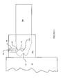
- the fin 26 b and the corresponding fin holder 28 b are shown in more detail to illustrate a mechanism for retaining the fins 26 a , 26 b in a non-deployed position as shown in FIG. 1 and for maintaining the fins 26 a , 26 b in a deployed position as shown in FIG. 2 .
- the fin 26 b is shown as including a first detent 42 that accepts a ball 44 that is urged into the detent 42 by a spring 46 .
- the ball 44 and the spring 46 may act as a retaining mechanism to retain the fin 26 b in a deployed position.
- the ball 44 and the spring 46 may be provided in a shaft 48 that is part of the fin holder 28 b .
- at least part of the shaft 48 may be part of the base 22 .
- the shaft 48 may be cylindrical, although other shapes may also be used, including, without limitation, a shaft having a square, rectangular, oval, etc. cross section.
- the fin 26 b may also include a second detent 52 that engages the retaining mechanism formed by the ball 44 and the spring 46 when the fin 26 b is in a non-deployed position as shown in FIG. 1 .
- the spring 46 urges the ball 44 into the detent 52 to retain the fin 26 b in a non-deployed position.
- other appropriate retaining mechanisms may be used in place of the ball 44 and the spring 46 .
- additional retaining mechanisms may be used in conjunction with the mechanism that engages the detent 52 .
- the fin 26 b is shown in a non-deployed position.
- the body 22 contains a deployment mechanism 62 having a gas generator 64 and a manifold 66 .
- the manifold 66 has a separate outlet for each fin and each outlet is in fluid communication with the gas generator 64 .
- each outlet may contain a piston that is acted upon by the gas from the generator 64 to push on and deploy all of the fins substantially simultaneously.
- the deployment mechanism 62 may be attached to the body 22 using any appropriate mechanism, including being bolted to the body through bolt holes (not shown) provided in the deployment mechanism 62 .
- a padding element 68 is provided to cushion the force of the piston to prevent the piston from damaging the fin 26 b .
- the padding element 68 may be made from a material that is somewhat softer than the material used for making the fin 26 b .
- the fin 26 b (and all the other fins) may be made from 7075-T6 aluminum while the padding element 68 may be made from a somewhat softer 6061-T6 aluminum.
- other appropriate materials may be used for either the fins 26 a , 26 b and/or the padding element 68 .
- the padding element 68 may be damaged during deployment while if the padding element 68 is too soft, the padding element 68 may deform without the fins 26 a , 26 b being properly deployed.
- the deployment mechanism 62 is shown in more detail as including a plurality of cylinders 72 a , 72 b in fluid communication with the gas generator 64 .
- Gas from the gas generator 64 may be released into the cylinders 72 a , 72 b in a rapid manner using an appropriate valve 74 that may be controlled externally by, for example, the electronics 34 shown in FIG. 1 and FIG. 2 .
- all of the fins 26 a , 26 b may be deployed simultaneously by actuating the valve 74 .
- the valve 74 may be actuated by the electronics 34 and/or by some other appropriate mechanism.
- the electronics 34 may also separately handle actuation of the fins 26 a , 26 b for navigation.
- a sensor may be used to detect when the system is being deployed (e.g., released from an aircraft in flight) and/or an external signal may be provided to indicate when the system is being deployed.
- actuation of the valve 74 is sufficient to deploy the fins 26 a , 26 b .
- the valve 74 may be implemented using a squib that is configured so that detonation of the squib causes the gas in the gas generator 64 to be rapidly released.
- the cylinder 72 a includes a piston 76 a while the cylinder 72 b includes a piston 76 b .
- a top of each of the pistons 76 a , 76 b is acted upon by the gas from the gas generator 64 so that the bottom of each of the pistons 76 a , 76 b extends outward from the manifold 66 to deploy the fins 26 a , 26 b .
- the bottoms of the pistons 76 a , 76 b may be coupled directly to the fins 26 a , 26 b .
- the bottoms of the pistons 76 a , 76 b may be coupled to the fins 26 a , 26 b indirectly through the padding element 68 , discussed above.
- the piston 76 a may be provided with a spring 78 a and the piston 76 b may be provided with a spring 78 b .
- the springs 78 a , 78 b may bias the pistons 76 a , 76 b in a direction opposite to the direction the pistons are pushed by gas from the gas generator 64 .
- the springs 78 a , 78 b may facilitate providing an appropriate force to deploy the fins 26 a , 26 b and, in addition, may facilitate assembly of the system by retaining the pistons 76 a , 76 b within the manifold 66 during assembly.
- an alternative deployment mechanism 62 ′ is shown in detail as including the cylinders 72 a , 72 b in fluid communication with an alternative gas generator 64 ′.
- gas from the gas generator 64 ′ may be released into the cylinders 72 a , 72 b in a rapid manner to deploy all of the fins 26 a , 26 b simultaneously.
- the alternative gas generator 64 ′ may be implemented using a chemical initiator, such as that provided by Special Devices, Inc. of Newhall, Calif. under part no. 103377.
- the alternative gas generator 64 ′ includes a reactive powder 65 that rapidly releases a significant amount of gas when ignited.
- the powder 65 may be ignited using an electrical resistive element/squib 79 that is coupled to and actuated by the electronics 34 . Operation of the pistons 76 a , 76 b and springs 78 a , 78 b may be like that of the deployment mechanism 62 of FIG. 5A , described above.
- the manifold 66 is shown from a top view as including additional cylinders 72 c , 72 d , additional pistons 76 c , 76 d , and additional springs 78 c , 78 d which operate in a manner similar to that discussed above in connection with the cylinders 72 a , 72 b , pistons 76 a , 76 b , and springs 78 a , 78 b .
- the fins 26 a , 26 b may not reliably deploy.
- the size is too small, the fins 26 a , 26 b (and/or other components) may become damaged in connection with deployment. Accordingly, it may be desirable to determine a minimal size (pressure) for the gas generator and then choose a size that is a nominal percentage above the minimal size.
- the amount of pressure, Pd, needed on the pistons 76 a - 76 d to deploy the fins 26 a , 26 b may be determined empirically. Similarly, the volume of the gas generator (e.g., the gas generator 64 or the gas generator 64 ′), the manifold 66 , and the cylinders 72 a - 72 d may also be determined.
- the gas generator e.g., the gas generator 64 or the gas generator 64 ′
- the manifold 66 e.g., the manifold 66
- the cylinders 72 a - 72 d may also be determined.
- V 1 is the sum of the volumes of the gas generator, the manifold 66 , and the cylinders 72 a , 72 d , and V 2 is a reference volume used to test/spec the gas generator
- Pg ( Pd*V 2)/ V 1
- This minimum may be then adjusted (increased) to account for expected variances in tolerance that could require more than 4800 p.s.i. to deploy the fins 26 a , 26 b and/or variances in actual values for V 1 and V 2 .
- 10% may be added to the calculated minimum pressure to provide an operating pressure of 1320 p.s.i. for the gas generator.
- the reference volume may be a volume used by the manufacturer/reseller to specify the capacity of the gas generator (e.g., delivers 1200 p.s.i. at 10 CC).
- the operating pressure for the gas generator should be present at a minimum operating temperature of the system (e.g., ⁇ 65° F.) and that the equation above may be used to determine the maximum pressure on the pistons 76 a - 76 d at a maximum operating temperature (e.g., +160° F.).
- a maximum operating temperature e.g., +160° F.
- the system may be adjusted by, for example, changing the volume of the gas generator and then determining a new operating pressure for the gas generator.
- the fin 26 b is shown in a non-deployed position as being retained by a second retaining mechanism that includes a spring clip 82 and a third retaining mechanism that includes a ball 84 and a detent 86 in the fin 26 b ,
- the ball 84 and the detent 86 may be like the ball 44 and the detent 42 discussed above.
- the spring clip 82 may be a metal deformable clip, as discussed in more detail elsewhere herein.
- the spring clip 82 is shown in more detail in profile.
- the spring clip 82 exerts a force in a direction indicated by the arrows in FIG. 8 to retain an edge of the fin 26 b that is shaped to be gripped by the spring clip 82 .
- the spring clip 82 may retain the fin 26 b in a non-deployed position until sufficient force is generated (e.g., by the deployment mechanism 62 , discussed above) to pull the fin 26 b away from the spring clip 82 .
- FIG. 9 an alternative implementation of the retaining mechanism of FIG. 3 is shown with the shaft 46 and the spring 48 .
- FIG. 9 shows a plunger 94 having a rounded end.
- the plunger 94 may be used instead of the ball 44 and/or instead of the ball 84 of FIG. 7 .
- any or all of the retaining mechanisms illustrated herein may be used in any combination and/or eliminated so that, for example, it is possible to use only the retaining mechanism of FIG. 3 , use the retaining mechanism of FIG. 3 in combination with the spring clip 82 , use all of the retaining mechanisms described herein, etc.
Landscapes
- Engineering & Computer Science (AREA)
- Physics & Mathematics (AREA)
- Fluid Mechanics (AREA)
- General Engineering & Computer Science (AREA)
- Health & Medical Sciences (AREA)
- General Health & Medical Sciences (AREA)
- Physical Education & Sports Medicine (AREA)
- Chemical & Material Sciences (AREA)
- Combustion & Propulsion (AREA)
- Mechanical Engineering (AREA)
- Ocean & Marine Engineering (AREA)
- Feeding, Discharge, Calcimining, Fusing, And Gas-Generation Devices (AREA)
Abstract
Description
Pg=(Pd*V2)/V1
For example, if it is determined that 4800 p.s.i. are needed to deploy the
Claims (16)
Priority Applications (3)
| Application Number | Priority Date | Filing Date | Title |
|---|---|---|---|
| US12/012,998 US8338769B1 (en) | 2008-02-07 | 2008-02-07 | Pyrotechnic fin deployment and retention mechanism |
| US12/927,310 US8183508B1 (en) | 2008-02-07 | 2010-11-10 | Pyrotechnic fin deployment and retention mechanism |
| US12/927,275 US8610042B2 (en) | 2008-02-07 | 2010-11-10 | Pyrotechnic fin deployment and retention mechanism |
Applications Claiming Priority (1)
| Application Number | Priority Date | Filing Date | Title |
|---|---|---|---|
| US12/012,998 US8338769B1 (en) | 2008-02-07 | 2008-02-07 | Pyrotechnic fin deployment and retention mechanism |
Related Child Applications (2)
| Application Number | Title | Priority Date | Filing Date |
|---|---|---|---|
| US12/927,275 Division US8610042B2 (en) | 2008-02-07 | 2010-11-10 | Pyrotechnic fin deployment and retention mechanism |
| US12/927,310 Division US8183508B1 (en) | 2008-02-07 | 2010-11-10 | Pyrotechnic fin deployment and retention mechanism |
Publications (1)
| Publication Number | Publication Date |
|---|---|
| US8338769B1 true US8338769B1 (en) | 2012-12-25 |
Family
ID=44340774
Family Applications (3)
| Application Number | Title | Priority Date | Filing Date |
|---|---|---|---|
| US12/012,998 Active 2030-04-01 US8338769B1 (en) | 2008-02-07 | 2008-02-07 | Pyrotechnic fin deployment and retention mechanism |
| US12/927,310 Active 2028-04-13 US8183508B1 (en) | 2008-02-07 | 2010-11-10 | Pyrotechnic fin deployment and retention mechanism |
| US12/927,275 Active 2029-10-17 US8610042B2 (en) | 2008-02-07 | 2010-11-10 | Pyrotechnic fin deployment and retention mechanism |
Family Applications After (2)
| Application Number | Title | Priority Date | Filing Date |
|---|---|---|---|
| US12/927,310 Active 2028-04-13 US8183508B1 (en) | 2008-02-07 | 2010-11-10 | Pyrotechnic fin deployment and retention mechanism |
| US12/927,275 Active 2029-10-17 US8610042B2 (en) | 2008-02-07 | 2010-11-10 | Pyrotechnic fin deployment and retention mechanism |
Country Status (1)
| Country | Link |
|---|---|
| US (3) | US8338769B1 (en) |
Cited By (5)
| Publication number | Priority date | Publication date | Assignee | Title |
|---|---|---|---|---|
| US20110186678A1 (en) * | 2008-02-07 | 2011-08-04 | Sankovic John R | Pyrotechnic fin deployment and retention mechanism |
| CN109253667A (en) * | 2018-08-31 | 2019-01-22 | 江西洪都航空工业集团有限责任公司 | A kind of Missile Folding rudder face longitudinal direction unfolding mechanism |
| US10641590B2 (en) * | 2016-10-26 | 2020-05-05 | Simmonds Precision Products, Inc. | Wing deployment and lock mechanism |
| US11150062B1 (en) * | 2016-06-23 | 2021-10-19 | Orbital Research Inc. | Control actuation system, devices and methods for missiles, munitions and projectiles |
| US20250121964A1 (en) * | 2023-10-11 | 2025-04-17 | The Boeing Company | Wing deployment apparatus and methods for aircraft |
Families Citing this family (10)
| Publication number | Priority date | Publication date | Assignee | Title |
|---|---|---|---|---|
| FR2942871B1 (en) * | 2009-03-06 | 2011-04-01 | Institut Franco Allemand De Rech De Saint Louis | DEVICE FOR CONTROLLING A MISSILE OR A PROJECTILE |
| WO2013066478A2 (en) * | 2011-08-26 | 2013-05-10 | Bae Systems | Apparatus for deploying stowed control surfaces of a projectile |
| US8866057B2 (en) * | 2011-10-17 | 2014-10-21 | Raytheon Company | Fin deployment method and apparatus |
| FR2986319B1 (en) * | 2012-01-27 | 2014-03-14 | Tda Armements Sas | PILOTAGE TRUNK FOR GUIDED MUNITION |
| US9296468B1 (en) * | 2012-09-21 | 2016-03-29 | Brandebury Tool Company, Inc. | Aerial vehicle with separation of winged surfaces in first and second flexed states |
| RU2522787C1 (en) * | 2013-03-15 | 2014-07-20 | Открытое акционерное общество "Корпорация "Тактическое ракетное вооружение" | Device of fixing in fold position of wing panels of unmanned aerial vehicle |
| US9121668B1 (en) | 2014-02-13 | 2015-09-01 | Raytheon Company | Aerial vehicle with combustible time-delay fuse |
| CN108190003B (en) * | 2017-12-28 | 2022-07-15 | 陕西中科博亿电子科技有限公司 | Unmanned aerial vehicle with buffer gear |
| DE102019008539A1 (en) * | 2019-12-10 | 2021-06-10 | Diehl Defence Gmbh & Co. Kg | Missile with pyrotechnic release |
| US11353300B2 (en) * | 2020-04-06 | 2022-06-07 | Raytheon Company | Modular gas operated fin deployment system |
Citations (21)
| Publication number | Priority date | Publication date | Assignee | Title |
|---|---|---|---|---|
| US3944168A (en) * | 1973-03-14 | 1976-03-16 | Etat Francais | Artillery projectile with spreading tail assembly |
| US4398682A (en) * | 1979-09-18 | 1983-08-16 | British Aerospace Public Limited Company | Displacement mechanism |
| US4560121A (en) * | 1983-05-17 | 1985-12-24 | The Garrett Corporation | Stabilization of automotive vehicle |
| US4624424A (en) * | 1984-11-07 | 1986-11-25 | The Boeing Company | On-board flight control drag actuator system |
| US4778127A (en) * | 1986-09-02 | 1988-10-18 | United Technologies Corporation | Missile fin deployment device |
| JPS6467598A (en) * | 1987-09-09 | 1989-03-14 | Mitsubishi Electric Corp | Guided missile |
| US4884766A (en) | 1988-05-25 | 1989-12-05 | The United States Of America As Represented By The Secretary Of The Air Force | Automatic fin deployment mechanism |
| EP0354088A1 (en) * | 1988-08-04 | 1990-02-07 | GIAT Industries | Device for opening projectile fins |
| US4923143A (en) * | 1988-11-15 | 1990-05-08 | Diehl Gmbh & Co. | Projectile having extendable wings |
| US5072891A (en) * | 1989-11-22 | 1991-12-17 | Applied Technology Associates | Combination actuator and coolant supply for missile and rocket vector control |
| US5950963A (en) | 1997-10-09 | 1999-09-14 | Versatron Corporation | Fin lock mechanism |
| US6073880A (en) | 1998-05-18 | 2000-06-13 | Versatron, Inc. | Integrated missile fin deployment system |
| US6446906B1 (en) | 2000-04-06 | 2002-09-10 | Versatron, Inc. | Fin and cover release system |
| US6450444B1 (en) | 2000-08-02 | 2002-09-17 | Raytheon Company | Fin lock system |
| US6695252B1 (en) * | 2002-09-18 | 2004-02-24 | Raytheon Company | Deployable fin projectile with outflow device |
| US6880780B1 (en) | 2003-03-17 | 2005-04-19 | General Dynamics Ordnance And Tactical Systems, Inc. | Cover ejection and fin deployment system for a gun-launched projectile |
| US7083140B1 (en) * | 2004-09-14 | 2006-08-01 | The United States Of America As Represented By The Secretary Of The Army | Full-bore artillery projectile fin development device and method |
| US20060213191A1 (en) | 2005-03-24 | 2006-09-28 | Snpe Materiaux Energetiques | Pyrotechnic actuator furnished with a pressure regulator member |
| US7195197B2 (en) * | 2005-02-11 | 2007-03-27 | Hr Textron, Inc. | Techniques for controlling a fin with unlimited adjustment and no backlash |
| US20080001023A1 (en) | 2005-10-05 | 2008-01-03 | General Dynamics Ordnance And Tactical Systems, Inc. | Fin retention and deployment mechanism |
| US7316370B2 (en) | 2005-06-13 | 2008-01-08 | Goodrich Corporation | Missile fin locking method and assembly |
Family Cites Families (13)
| Publication number | Priority date | Publication date | Assignee | Title |
|---|---|---|---|---|
| US3196793A (en) * | 1963-01-16 | 1965-07-27 | Milenkovic Veljko | Folded fin rocket |
| DE2342783C2 (en) * | 1973-08-24 | 1983-12-22 | Rheinmetall GmbH, 4000 Düsseldorf | Projectile equipped with a tail unit |
| US3946969A (en) * | 1974-07-30 | 1976-03-30 | The United States Of America As Represented By The Secretary Of The Army | Folding tail fins |
| US4175720A (en) * | 1978-04-05 | 1979-11-27 | The United States Of America As Represented By The Secretary Of The Navy | Retainer/release mechanism for use on fin stabilized gun fired projectiles |
| DE3328520C1 (en) * | 1983-08-06 | 1985-03-07 | Diehl GmbH & Co, 8500 Nürnberg | Tailplane for missiles |
| FR2644880B1 (en) * | 1989-03-24 | 1994-03-11 | Thomson Brandt Armements | OPENING SYSTEM FOR A PROJECTILE DEPLOYMENT STYLE |
| DE3917653A1 (en) * | 1989-05-31 | 1990-12-06 | Diehl Gmbh & Co | Erecting projectile fins by compression spring energy - applied to piston axially mobile in cylinder with apertured wall |
| GB8912632D0 (en) * | 1989-06-02 | 1992-11-04 | British Aerospace | Aerofoil deployment system |
| DE4020897C2 (en) * | 1990-06-30 | 1993-11-11 | Diehl Gmbh & Co | Device for unlocking and swinging out the rudder blades of a projectile |
| WO2002061363A2 (en) * | 2001-02-01 | 2002-08-08 | United Defense Lp | 2-d projectile trajectory corrector |
| US6948685B2 (en) * | 2003-10-27 | 2005-09-27 | Hr Textron, Inc. | Locking device with solenoid release pin |
| US8338769B1 (en) * | 2008-02-07 | 2012-12-25 | Simmonds Precision Products, Inc. | Pyrotechnic fin deployment and retention mechanism |
| IL189785A (en) * | 2008-02-26 | 2013-07-31 | Elbit Systems Ltd | Foldable and deployable panel |
-
2008
- 2008-02-07 US US12/012,998 patent/US8338769B1/en active Active
-
2010
- 2010-11-10 US US12/927,310 patent/US8183508B1/en active Active
- 2010-11-10 US US12/927,275 patent/US8610042B2/en active Active
Patent Citations (21)
| Publication number | Priority date | Publication date | Assignee | Title |
|---|---|---|---|---|
| US3944168A (en) * | 1973-03-14 | 1976-03-16 | Etat Francais | Artillery projectile with spreading tail assembly |
| US4398682A (en) * | 1979-09-18 | 1983-08-16 | British Aerospace Public Limited Company | Displacement mechanism |
| US4560121A (en) * | 1983-05-17 | 1985-12-24 | The Garrett Corporation | Stabilization of automotive vehicle |
| US4624424A (en) * | 1984-11-07 | 1986-11-25 | The Boeing Company | On-board flight control drag actuator system |
| US4778127A (en) * | 1986-09-02 | 1988-10-18 | United Technologies Corporation | Missile fin deployment device |
| JPS6467598A (en) * | 1987-09-09 | 1989-03-14 | Mitsubishi Electric Corp | Guided missile |
| US4884766A (en) | 1988-05-25 | 1989-12-05 | The United States Of America As Represented By The Secretary Of The Air Force | Automatic fin deployment mechanism |
| EP0354088A1 (en) * | 1988-08-04 | 1990-02-07 | GIAT Industries | Device for opening projectile fins |
| US4923143A (en) * | 1988-11-15 | 1990-05-08 | Diehl Gmbh & Co. | Projectile having extendable wings |
| US5072891A (en) * | 1989-11-22 | 1991-12-17 | Applied Technology Associates | Combination actuator and coolant supply for missile and rocket vector control |
| US5950963A (en) | 1997-10-09 | 1999-09-14 | Versatron Corporation | Fin lock mechanism |
| US6073880A (en) | 1998-05-18 | 2000-06-13 | Versatron, Inc. | Integrated missile fin deployment system |
| US6446906B1 (en) | 2000-04-06 | 2002-09-10 | Versatron, Inc. | Fin and cover release system |
| US6450444B1 (en) | 2000-08-02 | 2002-09-17 | Raytheon Company | Fin lock system |
| US6695252B1 (en) * | 2002-09-18 | 2004-02-24 | Raytheon Company | Deployable fin projectile with outflow device |
| US6880780B1 (en) | 2003-03-17 | 2005-04-19 | General Dynamics Ordnance And Tactical Systems, Inc. | Cover ejection and fin deployment system for a gun-launched projectile |
| US7083140B1 (en) * | 2004-09-14 | 2006-08-01 | The United States Of America As Represented By The Secretary Of The Army | Full-bore artillery projectile fin development device and method |
| US7195197B2 (en) * | 2005-02-11 | 2007-03-27 | Hr Textron, Inc. | Techniques for controlling a fin with unlimited adjustment and no backlash |
| US20060213191A1 (en) | 2005-03-24 | 2006-09-28 | Snpe Materiaux Energetiques | Pyrotechnic actuator furnished with a pressure regulator member |
| US7316370B2 (en) | 2005-06-13 | 2008-01-08 | Goodrich Corporation | Missile fin locking method and assembly |
| US20080001023A1 (en) | 2005-10-05 | 2008-01-03 | General Dynamics Ordnance And Tactical Systems, Inc. | Fin retention and deployment mechanism |
Non-Patent Citations (1)
| Title |
|---|
| Sankovic, John; Jul. 14, 2003 "Pyrotechnic Fin Lock Design", 5 pages. |
Cited By (7)
| Publication number | Priority date | Publication date | Assignee | Title |
|---|---|---|---|---|
| US20110186678A1 (en) * | 2008-02-07 | 2011-08-04 | Sankovic John R | Pyrotechnic fin deployment and retention mechanism |
| US8610042B2 (en) * | 2008-02-07 | 2013-12-17 | Simmonds Precision Products, Inc. | Pyrotechnic fin deployment and retention mechanism |
| US11150062B1 (en) * | 2016-06-23 | 2021-10-19 | Orbital Research Inc. | Control actuation system, devices and methods for missiles, munitions and projectiles |
| US10641590B2 (en) * | 2016-10-26 | 2020-05-05 | Simmonds Precision Products, Inc. | Wing deployment and lock mechanism |
| CN109253667A (en) * | 2018-08-31 | 2019-01-22 | 江西洪都航空工业集团有限责任公司 | A kind of Missile Folding rudder face longitudinal direction unfolding mechanism |
| US20250121964A1 (en) * | 2023-10-11 | 2025-04-17 | The Boeing Company | Wing deployment apparatus and methods for aircraft |
| US12391412B2 (en) * | 2023-10-11 | 2025-08-19 | The Boeing Company | Wing deployment apparatus and methods for aircraft |
Also Published As
| Publication number | Publication date |
|---|---|
| US8610042B2 (en) | 2013-12-17 |
| US8183508B1 (en) | 2012-05-22 |
| US20110186678A1 (en) | 2011-08-04 |
Similar Documents
| Publication | Publication Date | Title |
|---|---|---|
| US8338769B1 (en) | Pyrotechnic fin deployment and retention mechanism | |
| US8640589B2 (en) | Projectile modification method | |
| US9500454B1 (en) | Mortar projectile with guided deceleration system for delivering a payload | |
| US8220392B1 (en) | Launchable grenade system | |
| US11255648B2 (en) | Projectile with a range extending wing assembly | |
| US8415598B1 (en) | Extendable fins for a tube-launched projectile | |
| KR20070094806A (en) | Single Axis Pinout System | |
| US6352218B1 (en) | Method and device for a fin-stabilized base-bleed shell | |
| US6978967B1 (en) | Space saving fin deployment system for munitions and missiles | |
| US7004425B2 (en) | Flying body for firing from a tube with over-caliber stabilizers | |
| IL186284A (en) | Ejectable aerodynamic stability and control | |
| US5398588A (en) | Missile system with telescoping launch tube | |
| US7946208B1 (en) | Ejection system for deploying a store | |
| US20150053193A1 (en) | Launcher with multi-part pusher, and method | |
| US6450444B1 (en) | Fin lock system | |
| US7097132B2 (en) | Apparatus and method for selectivity locking a fin assembly | |
| US20150369577A1 (en) | Non-lethal projectile | |
| US11187506B1 (en) | Method for fin deployment using gun gas pressure | |
| US11353300B2 (en) | Modular gas operated fin deployment system | |
| US9482185B1 (en) | Thermal rocket initiator mechanism and rocket system incorporating same | |
| USH1150H (en) | Parachute recovery system for projectiles | |
| KR101213041B1 (en) | Wing assembly, distributed flying object and method for opening wing of distributed flying object | |
| US6769643B2 (en) | Projectile to be fired from a barrel with an over-caliber control surface assembly | |
| CN108639543B (en) | Device for conveying articles at high speed | |
| US20220236041A1 (en) | Aero-assisted missile fin or wing deployment system |
Legal Events
| Date | Code | Title | Description |
|---|---|---|---|
| AS | Assignment |
Owner name: SIMMONDS PRECISION PRODUCTS, INC., VERMONT Free format text: ASSIGNMENT OF ASSIGNORS INTEREST;ASSIGNOR:SANKOVIC, JOHN R;REEL/FRAME:020664/0046 Effective date: 20080301 |
|
| STCF | Information on status: patent grant |
Free format text: PATENTED CASE |
|
| FPAY | Fee payment |
Year of fee payment: 4 |
|
| MAFP | Maintenance fee payment |
Free format text: PAYMENT OF MAINTENANCE FEE, 8TH YEAR, LARGE ENTITY (ORIGINAL EVENT CODE: M1552); ENTITY STATUS OF PATENT OWNER: LARGE ENTITY Year of fee payment: 8 |
|
| MAFP | Maintenance fee payment |
Free format text: PAYMENT OF MAINTENANCE FEE, 12TH YEAR, LARGE ENTITY (ORIGINAL EVENT CODE: M1553); ENTITY STATUS OF PATENT OWNER: LARGE ENTITY Year of fee payment: 12 |
|
| AS | Assignment |
Owner name: GOLDMAN SACHS BANK USA, AS AGENT, NEW YORK Free format text: SECURITY INTEREST;ASSIGNOR:SIMMONDS PRECISION PRODUCTS, INC.;REEL/FRAME:073465/0631 Effective date: 20251104 |
|
| AS | Assignment |
Owner name: THE BANK OF NEW YORK MELLON TRUST COMPANY, N.A., ILLINOIS Free format text: SECURITY INTEREST;ASSIGNOR:SIMMONDS PRECISION PRODUCTS, INC.;REEL/FRAME:073545/0454 Effective date: 20251104 Owner name: THE BANK OF NEW YORK MELLON TRUST COMPANY, N.A., ILLINOIS Free format text: SECURITY INTEREST;ASSIGNOR:SIMMONDS PRECISION PRODUCTS, INC.;REEL/FRAME:073590/0028 Effective date: 20251104 Owner name: THE BANK OF NEW YORK MELLON TRUST COMPANY, N.A., ILLINOIS Free format text: SECURITY INTEREST;ASSIGNOR:SIMMONDS PRECISION PRODUCTS, INC.;REEL/FRAME:073560/0086 Effective date: 20251104 Owner name: THE BANK OF NEW YORK MELLON TRUST COMPANY, N.A., ILLINOIS Free format text: SECURITY INTEREST;ASSIGNOR:SIMMONDS PRECISION PRODUCTS, INC.;REEL/FRAME:073560/0144 Effective date: 20251104 Owner name: THE BANK OF NEW YORK MELLON TRUST COMPANY, N.A., ILLINOIS Free format text: SECURITY INTEREST;ASSIGNOR:SIMMONDS PRECISION PRODUCTS, INC.;REEL/FRAME:073545/0100 Effective date: 20251104 Owner name: THE BANK OF NEW YORK MELLON TRUST COMPANY, N.A., ILLINOIS Free format text: SECURITY INTEREST;ASSIGNOR:SIMMONDS PRECISION PRODUCTS, INC.;REEL/FRAME:073560/0181 Effective date: 20251104 Owner name: THE BANK OF NEW YORK MELLON TRUST COMPANY, N.A., ILLINOIS Free format text: SECURITY INTEREST;ASSIGNOR:SIMMONDS PRECISION PRODUCTS, INC.;REEL/FRAME:073560/0239 Effective date: 20251104 |