US8335082B2 - Heat dissipating apparatus - Google Patents
Heat dissipating apparatus Download PDFInfo
- Publication number
- US8335082B2 US8335082B2 US13/095,863 US201113095863A US8335082B2 US 8335082 B2 US8335082 B2 US 8335082B2 US 201113095863 A US201113095863 A US 201113095863A US 8335082 B2 US8335082 B2 US 8335082B2
- Authority
- US
- United States
- Prior art keywords
- tray
- heat dissipating
- cooler
- dissipating apparatus
- air
- Prior art date
- Legal status (The legal status is an assumption and is not a legal conclusion. Google has not performed a legal analysis and makes no representation as to the accuracy of the status listed.)
- Expired - Fee Related, expires
Links
Images


Classifications
-
- G—PHYSICS
- G06—COMPUTING; CALCULATING OR COUNTING
- G06F—ELECTRIC DIGITAL DATA PROCESSING
- G06F1/00—Details not covered by groups G06F3/00 - G06F13/00 and G06F21/00
- G06F1/16—Constructional details or arrangements
- G06F1/20—Cooling means
Definitions
- the present disclosure relates to heat dissipating apparatuses, and particularly to a heat dissipating apparatus in a case.
- VRM Voltage Regulator Module
- CPU Central Processing Unit
- FIG. 1 is an assembled, isometric view of a heat dissipating apparatus and a host in accordance with one embodiment.
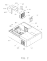
- FIG. 2 is an exploded, isometric view of the heat dissipating apparatus and a host in accordance with one embodiment.
- FIG. 3 is an assembled, isometric view of the heat dissipating apparatus.
- FIG. 4 is an isometric view of an air duct of the heat dissipating apparatus.
- FIG. 5 is similar to FIG. 4 , but viewed from another aspect.
- a heat dissipating apparatus 100 is capable of being secured to a host 30 and includes a cooler 10 , a cooling fan 20 and an air duct 60 .
- the host 30 includes a bottom plate 31 , a side plate 33 , a rear plate 35 , a power supply 40 and a circuit board 50 .
- the bottom plate 31 is substantially perpendicular to the side plate 33 and the rear plate 35 .
- the side plate 33 is substantially perpendicular to the rear plate 35 .
- the side plate 33 defines a plurality of air inlets 331
- the rear plate 35 defines a plurality of air outlets 351 .
- the circuit board 50 is located on the bottom plate 31 .
- a CPU 51 , a VRM 52 , and a plurality of connectors 53 are located on the circuit board 50 .
- the circuit board 50 may be a computer motherboard.
- a power supply fan 41 is located in the power supply 40 .
- the VRM 52 is located between the power supply fan 41 and the CPU 51 .
- the VRM 52 is adjacent to the CPU 51
- the connectors 53 are adjacent to the rear plate 35 below the air outlets 351 .
- the cooler 10 includes a bottom wall 11 , a top wall 13 , a first sidewall 15 and a second wall (not shown).
- the bottom wall 11 is substantially parallel to the top wall 13 and perpendicular to the first sidewall 15 .
- a plurality of fins 16 is located among the bottom wall 11 , the top wall 13 , the first sidewall 15 , and the second sidewall. The fins 16 are substantially perpendicular to the bottom wall 11 .
- a channel is defined between each two adjacent fins 16 .
- the air duct 60 includes a first body 61 and a second body 63 located on the first body 61 .
- the first body 61 includes a first top tray 611 , a first bottom tray 613 , a first side tray 615 and a second side tray 617 .
- the first top tray 611 is substantially parallel to the first bottom tray 613 .
- the first top tray 611 and the first bottom tray 613 are trapezium.
- the second body 63 includes a second top tray 631 , a third top tray 633 , a third side tray 635 and a fourth side tray 637 . An angle is defined between the second top tray 631 and the third top tray 633 .
- the angle is obtuse.
- the third side tray 635 extends from a side edge of the second top tray 631 and is connected to the first side tray 615 .
- the fourth side tray 637 is opposite to the third side tray 635 and is connected to the second side tray 617 , the second top tray 631 and the third top tray 633 .
- An air guiding board 639 is located on the fourth side tray 637 perpendicular to the fourth side tray 637 .
- the air guiding board 639 extends aslant from a side edge of the fourth side tray 637 . A distance between the air guiding board 639 and the fourth side tray 637 is approximately equal to that between the fourth side tray 637 and the cooler 10 .
- the cooler 10 is located among the third top tray 633 , the fourth side tray 637 and the third side tray 635 .
- the third top tray 633 is located above the top wall 13 of the cooler 10 .
- the third side tray 635 abuts an edge of the first sidewall 15 .
- a gap 80 is defined between the fourth side tray 637 and the second sidewall of the cooler 10 (referring to FIG. 3 ). The width of the gap 80 is approximately equal to that of the fourth side tray 637 .
- the cooling fan 20 is secured to the bottom wall 11 and adjacent to the fourth side tray 637 .
- the cooler 10 abuts the CPU 51 .
- the second body 63 covers the cooler 10 and the VRM 52 , and the VRM 52 is located between the fourth side tray 637 and the second sidewall.
- An angle is defined between the air guiding board 639 and the circuit board. In one embodiment, the angle is acute.
- the first body 61 is opposite to the air outlets 351 , and the lower surface of the first bottom tray 613 abuts the connectors 53 .
- the air flowed into the cooling fan 20 discharges the heat caused by the CPU 51 out off the host 30 via the channel formed by the fins 16 , the second body 63 , the first body 61 and the outlets 351 .
- the VRM 52 is cooled.
Abstract
Description
Claims (20)
Applications Claiming Priority (3)
| Application Number | Priority Date | Filing Date | Title |
|---|---|---|---|
| CN2010102888103A CN102411413A (en) | 2010-09-21 | 2010-09-21 | Radiating device |
| CN201010288810 | 2010-09-21 | ||
| CN201010288810.3 | 2010-09-21 |
Publications (2)
| Publication Number | Publication Date |
|---|---|
| US20120067553A1 US20120067553A1 (en) | 2012-03-22 |
| US8335082B2 true US8335082B2 (en) | 2012-12-18 |
Family
ID=45816677
Family Applications (1)
| Application Number | Title | Priority Date | Filing Date |
|---|---|---|---|
| US13/095,863 Expired - Fee Related US8335082B2 (en) | 2010-09-21 | 2011-04-28 | Heat dissipating apparatus |
Country Status (2)
| Country | Link |
|---|---|
| US (1) | US8335082B2 (en) |
| CN (1) | CN102411413A (en) |
Cited By (6)
| Publication number | Priority date | Publication date | Assignee | Title |
|---|---|---|---|---|
| US20120327586A1 (en) * | 2011-06-24 | 2012-12-27 | Hon Hai Precision Industry Co., Ltd. | Computer system with airflow guiding duct |
| US20170131750A1 (en) * | 2015-11-10 | 2017-05-11 | Fujitsu Limited | Cooling device and information processing apparatus |
| US20170311487A1 (en) * | 2014-09-29 | 2017-10-26 | Hewlett Packard Enterprise Development Lp | Fan controlled ambient air cooling of equipment in a controlled airflow environment |
| US20180032464A1 (en) * | 2011-03-22 | 2018-02-01 | Amazon Technologies, Inc. | Modular mass storage system |
| US11174876B2 (en) * | 2017-10-12 | 2021-11-16 | Fujifilm Business Innovation Corp. | Blower |
| USD950507S1 (en) * | 2020-04-28 | 2022-05-03 | Aic Inc. | Heat sink |
Families Citing this family (6)
| Publication number | Priority date | Publication date | Assignee | Title |
|---|---|---|---|---|
| US9075581B2 (en) * | 2011-04-19 | 2015-07-07 | Germane Systems, Llc | Apparatus and method for cooling electrical components of a computer |
| CN103813690A (en) * | 2012-11-08 | 2014-05-21 | 鸿富锦精密工业(深圳)有限公司 | Wind scooper |
| CN104346866A (en) * | 2013-08-05 | 2015-02-11 | 鸿富锦精密工业(武汉)有限公司 | Heating-refrigerating switching structure |
| US10299403B2 (en) * | 2015-09-23 | 2019-05-21 | Advanced Micro Devices, Inc. | Modular thermal solution for high-performance processors |
| CN109213293A (en) * | 2017-06-30 | 2019-01-15 | 鸿富锦精密工业(武汉)有限公司 | Radiator |
| CN108628425A (en) * | 2018-05-04 | 2018-10-09 | 曙光信息产业(北京)有限公司 | A kind of server radiating method and apparatus |
Citations (11)
| Publication number | Priority date | Publication date | Assignee | Title |
|---|---|---|---|---|
| US6400568B1 (en) * | 2001-07-11 | 2002-06-04 | Sun Microsystems, Inc. | Method and apparatus for cooling electronic components |
| US6938682B2 (en) * | 2003-10-18 | 2005-09-06 | Hon Hai Precision Ind. Co., Ltd. | Heat dissipation device |
| US6989988B2 (en) * | 2003-02-21 | 2006-01-24 | Hewlett-Packard Development Company, L.P. | Duct for cooling multiple components in a processor-based device |
| US20060181846A1 (en) * | 2005-02-11 | 2006-08-17 | Farnsworth Arthur K | Cooling system for a computer environment |
| US20070091566A1 (en) * | 2005-10-24 | 2007-04-26 | Hon Hai Precision Industry Co., Ltd. | Fan duct and heat dissipation module comprising the same |
| US7215548B1 (en) * | 2006-03-20 | 2007-05-08 | Foxconn Technology Co., Ltd. | Heat dissipating device having a fin also functioning as a fan duct |
| US7256997B2 (en) * | 2005-11-01 | 2007-08-14 | Fu Zhun Precision Industry (Shenzhen) Co., Ltd. | Heat dissipating device having a fan duct |
| US20080101018A1 (en) * | 2006-10-27 | 2008-05-01 | Foxconn Technology Co., Ltd. | Heat dissipation device |
| US20080151498A1 (en) * | 2004-09-03 | 2008-06-26 | Jie Zhang | Heat-Radiating Device with a Guide Structure |
| US7401642B2 (en) * | 2003-12-19 | 2008-07-22 | Hon Hai Precision Industry Co., Ltd. | Heat sink with heat pipes |
| US7933119B2 (en) * | 2009-07-31 | 2011-04-26 | Hewlett-Packard Development Company, L.P. | Heat transfer systems and methods |
-
2010
- 2010-09-21 CN CN2010102888103A patent/CN102411413A/en active Pending
-
2011
- 2011-04-28 US US13/095,863 patent/US8335082B2/en not_active Expired - Fee Related
Patent Citations (11)
| Publication number | Priority date | Publication date | Assignee | Title |
|---|---|---|---|---|
| US6400568B1 (en) * | 2001-07-11 | 2002-06-04 | Sun Microsystems, Inc. | Method and apparatus for cooling electronic components |
| US6989988B2 (en) * | 2003-02-21 | 2006-01-24 | Hewlett-Packard Development Company, L.P. | Duct for cooling multiple components in a processor-based device |
| US6938682B2 (en) * | 2003-10-18 | 2005-09-06 | Hon Hai Precision Ind. Co., Ltd. | Heat dissipation device |
| US7401642B2 (en) * | 2003-12-19 | 2008-07-22 | Hon Hai Precision Industry Co., Ltd. | Heat sink with heat pipes |
| US20080151498A1 (en) * | 2004-09-03 | 2008-06-26 | Jie Zhang | Heat-Radiating Device with a Guide Structure |
| US20060181846A1 (en) * | 2005-02-11 | 2006-08-17 | Farnsworth Arthur K | Cooling system for a computer environment |
| US20070091566A1 (en) * | 2005-10-24 | 2007-04-26 | Hon Hai Precision Industry Co., Ltd. | Fan duct and heat dissipation module comprising the same |
| US7256997B2 (en) * | 2005-11-01 | 2007-08-14 | Fu Zhun Precision Industry (Shenzhen) Co., Ltd. | Heat dissipating device having a fan duct |
| US7215548B1 (en) * | 2006-03-20 | 2007-05-08 | Foxconn Technology Co., Ltd. | Heat dissipating device having a fin also functioning as a fan duct |
| US20080101018A1 (en) * | 2006-10-27 | 2008-05-01 | Foxconn Technology Co., Ltd. | Heat dissipation device |
| US7933119B2 (en) * | 2009-07-31 | 2011-04-26 | Hewlett-Packard Development Company, L.P. | Heat transfer systems and methods |
Cited By (10)
| Publication number | Priority date | Publication date | Assignee | Title |
|---|---|---|---|---|
| US20180032464A1 (en) * | 2011-03-22 | 2018-02-01 | Amazon Technologies, Inc. | Modular mass storage system |
| US10198390B2 (en) * | 2011-03-22 | 2019-02-05 | Amazon Technologies, Inc. | Modular mass storage system |
| US20120327586A1 (en) * | 2011-06-24 | 2012-12-27 | Hon Hai Precision Industry Co., Ltd. | Computer system with airflow guiding duct |
| US8737060B2 (en) * | 2011-06-24 | 2014-05-27 | Hong Fu Jin Precision Industry (Wuhan) Co., Ltd. | Computer system with airflow guiding duct |
| US20170311487A1 (en) * | 2014-09-29 | 2017-10-26 | Hewlett Packard Enterprise Development Lp | Fan controlled ambient air cooling of equipment in a controlled airflow environment |
| US10993353B2 (en) * | 2014-09-29 | 2021-04-27 | Hewlett Packard Enterprise Development Lp | Fan controlled ambient air cooling of equipment in a controlled airflow environment |
| US20170131750A1 (en) * | 2015-11-10 | 2017-05-11 | Fujitsu Limited | Cooling device and information processing apparatus |
| US11079815B2 (en) * | 2015-11-10 | 2021-08-03 | Fujitsu Limited | Cooling device and information processing apparatus |
| US11174876B2 (en) * | 2017-10-12 | 2021-11-16 | Fujifilm Business Innovation Corp. | Blower |
| USD950507S1 (en) * | 2020-04-28 | 2022-05-03 | Aic Inc. | Heat sink |
Also Published As
| Publication number | Publication date |
|---|---|
| CN102411413A (en) | 2012-04-11 |
| US20120067553A1 (en) | 2012-03-22 |
Similar Documents
| Publication | Publication Date | Title |
|---|---|---|
| US8335082B2 (en) | Heat dissipating apparatus | |
| US8514574B2 (en) | Heat dissipating apparatus | |
| US8564948B2 (en) | Electronic device | |
| US8072753B2 (en) | Computer system | |
| US8300409B2 (en) | Fan duct for electronic components of electronic device | |
| US7414842B2 (en) | Heat dissipation device | |
| US9277672B2 (en) | Television, radiating member, and electronic apparatus | |
| US20090040717A1 (en) | Heat dissipating device with air duct | |
| US20070274038A1 (en) | Heat dissipating device | |
| US20120090888A1 (en) | Enclosure of electronic device | |
| US20120327589A1 (en) | Computer system with airflow guiding duct | |
| US20090168330A1 (en) | Electronic device with airflow guiding duct | |
| US8462497B2 (en) | Computer system | |
| US8363401B2 (en) | Air guiding device and heat dissipation system having same | |
| US8448695B2 (en) | Heat dissipating apparatus | |
| US20140160671A1 (en) | Motherboard cooling system | |
| US7929302B2 (en) | Cooling device | |
| US8659894B2 (en) | Computer system with heat dissipation apparatus | |
| US8081453B2 (en) | Adhesive air guiding device and motherboard having the same | |
| US9125300B2 (en) | Electronic device with heat sink structure | |
| US20090010757A1 (en) | Centrifugal blower | |
| US20100214738A1 (en) | Portable electronic device and dissipating structure thereof | |
| US20120120595A1 (en) | Computer system with airflow guiding duct | |
| US8120909B2 (en) | Computer system with airflow guiding duct | |
| US20150163959A1 (en) | Electronic device with fan module |
Legal Events
| Date | Code | Title | Description |
|---|---|---|---|
| AS | Assignment |
Owner name: HONG FU JIN PRECISION INDUSTRY (SHENZHEN) CO., LTD Free format text: ASSIGNMENT OF ASSIGNORS INTEREST;ASSIGNORS:SUN, HONG-ZHI;CHEN, CHEN;LI, YANG;REEL/FRAME:026190/0973 Effective date: 20110426 Owner name: HON HAI PRECISION INDUSTRY CO., LTD., TAIWAN Free format text: ASSIGNMENT OF ASSIGNORS INTEREST;ASSIGNORS:SUN, HONG-ZHI;CHEN, CHEN;LI, YANG;REEL/FRAME:026190/0973 Effective date: 20110426 |
|
| REMI | Maintenance fee reminder mailed | ||
| LAPS | Lapse for failure to pay maintenance fees | ||
| STCH | Information on status: patent discontinuation |
Free format text: PATENT EXPIRED DUE TO NONPAYMENT OF MAINTENANCE FEES UNDER 37 CFR 1.362 |
|
| FP | Lapsed due to failure to pay maintenance fee |
Effective date: 20161218 |