US8331518B2 - Wireless communication apparatus for receiving packets transmitted with delay amounts different for respective transmission branches - Google Patents
Wireless communication apparatus for receiving packets transmitted with delay amounts different for respective transmission branches Download PDFInfo
- Publication number
- US8331518B2 US8331518B2 US12/555,267 US55526709A US8331518B2 US 8331518 B2 US8331518 B2 US 8331518B2 US 55526709 A US55526709 A US 55526709A US 8331518 B2 US8331518 B2 US 8331518B2
- Authority
- US
- United States
- Prior art keywords
- synchronous
- reception branches
- branches
- reception
- processing unit
- Prior art date
- Legal status (The legal status is an assumption and is not a legal conclusion. Google has not performed a legal analysis and makes no representation as to the accuracy of the status listed.)
- Expired - Fee Related, expires
Links
Images


Classifications
-
- H—ELECTRICITY
- H04—ELECTRIC COMMUNICATION TECHNIQUE
- H04L—TRANSMISSION OF DIGITAL INFORMATION, e.g. TELEGRAPHIC COMMUNICATION
- H04L27/00—Modulated-carrier systems
- H04L27/26—Systems using multi-frequency codes
- H04L27/2601—Multicarrier modulation systems
- H04L27/2647—Arrangements specific to the receiver only
- H04L27/2655—Synchronisation arrangements
- H04L27/2656—Frame synchronisation, e.g. packet synchronisation, time division duplex [TDD] switching point detection or subframe synchronisation
-
- H—ELECTRICITY
- H04—ELECTRIC COMMUNICATION TECHNIQUE
- H04L—TRANSMISSION OF DIGITAL INFORMATION, e.g. TELEGRAPHIC COMMUNICATION
- H04L27/00—Modulated-carrier systems
- H04L27/26—Systems using multi-frequency codes
- H04L27/2601—Multicarrier modulation systems
- H04L27/2647—Arrangements specific to the receiver only
- H04L27/2655—Synchronisation arrangements
- H04L27/2668—Details of algorithms
- H04L27/2673—Details of algorithms characterised by synchronisation parameters
- H04L27/2675—Pilot or known symbols
-
- H—ELECTRICITY
- H04—ELECTRIC COMMUNICATION TECHNIQUE
- H04L—TRANSMISSION OF DIGITAL INFORMATION, e.g. TELEGRAPHIC COMMUNICATION
- H04L5/00—Arrangements affording multiple use of the transmission path
- H04L5/0001—Arrangements for dividing the transmission path
- H04L5/0014—Three-dimensional division
- H04L5/0023—Time-frequency-space
-
- H—ELECTRICITY
- H04—ELECTRIC COMMUNICATION TECHNIQUE
- H04L—TRANSMISSION OF DIGITAL INFORMATION, e.g. TELEGRAPHIC COMMUNICATION
- H04L25/00—Baseband systems
- H04L25/02—Details ; arrangements for supplying electrical power along data transmission lines
- H04L25/03—Shaping networks in transmitter or receiver, e.g. adaptive shaping networks
- H04L25/03006—Arrangements for removing intersymbol interference
- H04L2025/0335—Arrangements for removing intersymbol interference characterised by the type of transmission
- H04L2025/03375—Passband transmission
- H04L2025/03414—Multicarrier
-
- H—ELECTRICITY
- H04—ELECTRIC COMMUNICATION TECHNIQUE
- H04L—TRANSMISSION OF DIGITAL INFORMATION, e.g. TELEGRAPHIC COMMUNICATION
- H04L25/00—Baseband systems
- H04L25/02—Details ; arrangements for supplying electrical power along data transmission lines
- H04L25/03—Shaping networks in transmitter or receiver, e.g. adaptive shaping networks
- H04L25/03006—Arrangements for removing intersymbol interference
- H04L2025/0335—Arrangements for removing intersymbol interference characterised by the type of transmission
- H04L2025/03426—Arrangements for removing intersymbol interference characterised by the type of transmission transmission using multiple-input and multiple-output channels
-
- H—ELECTRICITY
- H04—ELECTRIC COMMUNICATION TECHNIQUE
- H04L—TRANSMISSION OF DIGITAL INFORMATION, e.g. TELEGRAPHIC COMMUNICATION
- H04L25/00—Baseband systems
- H04L25/02—Details ; arrangements for supplying electrical power along data transmission lines
- H04L25/0202—Channel estimation
- H04L25/0204—Channel estimation of multiple channels
-
- H—ELECTRICITY
- H04—ELECTRIC COMMUNICATION TECHNIQUE
- H04L—TRANSMISSION OF DIGITAL INFORMATION, e.g. TELEGRAPHIC COMMUNICATION
- H04L27/00—Modulated-carrier systems
- H04L27/26—Systems using multi-frequency codes
- H04L27/2601—Multicarrier modulation systems
- H04L27/2602—Signal structure
- H04L27/261—Details of reference signals
- H04L27/2613—Structure of the reference signals
-
- H—ELECTRICITY
- H04—ELECTRIC COMMUNICATION TECHNIQUE
- H04L—TRANSMISSION OF DIGITAL INFORMATION, e.g. TELEGRAPHIC COMMUNICATION
- H04L7/00—Arrangements for synchronising receiver with transmitter
- H04L7/04—Speed or phase control by synchronisation signals
- H04L7/041—Speed or phase control by synchronisation signals using special codes as synchronising signal
- H04L7/042—Detectors therefor, e.g. correlators, state machines
Definitions
- the present invention relates to a wireless communication apparatus and method for data communications where the capacity of transmission is extended using a spatial multiplexing communication scheme (multiple input multiple output; MIMO) in combination with a transmitter having a plurality of antennas, and to a computer program applicable to the wireless communication apparatus and method.
- MIMO multiple input multiple output
- the present invention relates to a wireless communication apparatus and method for data communications which receives packets transmitted after beamforming processing with cyclic delay diversity (CDD), and to a computer program applicable to the wireless communication apparatus and method.
- CDD cyclic delay diversity
- the present invention relates to a wireless communication apparatus and method where suitable synchronous timing is obtained based on correlation processing of preamble from packets transmitted with different delay amounts for respective transmission branches, and to a computer program applicable to the wireless communication apparatus and method. Still more preferably, the present invention relates to the present invention relates to a wireless communication apparatus and method where a dynamic range to be indispensable for receiving packets transmitted with different delay amounts for respective transmission branches is diminished, and to a computer program applicable to the wireless communication apparatus and method.
- Wireless networks have become a focus of attention, as systems free from wiring used for known wired-communication methods.
- EE The Institute of Electrical and Electronics Engineers 802.11 and/or IEEE 802.15 can be named, as an ordinary standard relating to the wireless network.
- IEEE 802.11a/g an OFDM (Orthogonal Frequency Division Multiplexing) modulation method which is one of multi-carrier systems is used, as an ordinary standard of wireless LANs.
- IEEE 802.11a/g When IEEE 802.11a/g standards are used, a modulation method achieving a communication speed of 54 Mbps at the maximum is supported. However, a next-generation wireless-LAN standard capable of achieving a higher bit rate has been demanded.
- the MIMO (Multi-Input Multi-Output) communication draws attention as one of technologies for realizing high-speed wireless communication. For instance, IEEE 802.11n (TGn), an extended standard of IEEE 802.11, employs the OFDM_MIMO communication system.
- MIMO is a communication system that realizes spatial multiplexing streams in each of a transmitter and a receiver provided with a plurality of antenna elements.
- the transmitter performs space-time coding on a plurality of transmitted data and distributes the multiplexed data to a plurality of transmission antennas, followed by transmitting the data to a channel.
- the receiver receives signals from the transmission branch by a plurality of receiving antennas through the channel and performs space-time decoding on the received signals to divide them into a plurality of transmission data.
- the receiving branch obtains the original data without any cross talk between streams.
- the MIMO communication system can attain an increase in communication speed by extending the capacity of transmission depending on the number of antennas without extending the range of frequencies.
- the MIMO communication system has good frequency utilization efficiency because of using spatial multiplexing.
- MIMO is a communication mode using a channel characteristic, and it is different from a mere transceiver adaptive array.
- a transmission weight matrix and a reception weight matrix are calculated using channel-matrix H, respectively.
- the transmission weight matrix is provided for carrying out spatial multiplexing of transmission streams from a plurality of transmission branches in the transmitter.
- the reception weight matrix is provided for carrying out spatial separation of the spatial multiplexing signals into a plurality of original streams in the receiver.
- the channel-matrix H is the numerical matrix using channel information corresponding to a pair of transmission/reception antennas as an element.
- channel information used herein is a said here is a transfer function having a phase and amplitude as components.
- a channel matrix can be presumed by carrying out a frame exchange sequence including training series constructed of known reference symbols for exciting the channel matrix between the transmitter and the receiver.
- a wireless communication apparatus for correctly receiving a MIMO_OFDM signal has been disclosed in Japanese Published Patent Application No. 2007-221187.
- the usual synchronization acquisition processing is performed using a field for synchronization acquisition in a preamble and a signal is then detected as a MIMO signal to which the addition of a cyclic shift signal is performed between streams, allowing synchronous timing to be adjusted based on the cyclic shift thereof to correctly receive the MIMO_OFDM signal.
- a preamble having a repetition of a known training sequence is generally added to the head of a packet.
- a receiver performs synchronous processing using such a preamble. Specifically, if the receiver finds a packet by detecting the preamble, the receiver performs subsequent processing, such as the check of precise receiving timing, frequency-offset removing operation, and optionally normalization of received signal electric power (setup of automatic gain control (AGC); AGC gain). Then, the valid symbol section of an OFDM symbol is extracted to feed a received signal to a fast Fourier transform (FFT).
- FFT fast Fourier transform
- the present inventors have recognized an outstanding wireless communication apparatus, wireless communication method, and computer program, which are allowed to suitably receive packets subjected to CDD and beamforming-transmitted.
- the present inventors have also recognized an outstanding wireless communication apparatus, wireless communication method, and computer program, which are allowed to obtain suitable synchronous timing based on correlation processing of preamble from packets transmitted with different delay amounts for respective transmission branches.
- the present inventors have further recognized an outstanding wireless communication apparatus, wireless communication method, and computer program, which are allowed to diminish a dynamic range to be indispensable for receiving packets transmitted with different delay amounts for respective transmission branches.
- the present invention has been made in view of the above circumstances.
- a wireless communication apparatus for receiving packets transmitted with delay amounts different for the respective transmission branches, including:
- a synchronous processing unit for detecting synchronous timing independently for the respective reception branches
- a signal processing unit for performing decoding processing and other kinds of processing subsequent to the synchronous timing for the respective reception branches.
- the synchronous processing unit may be configured as follows:
- the synchronous processing unit When the synchronous processing unit detects the synchronous timing for the respective reception branches by autocorrelation processing of a repetitive portion of time waveform for a preamble period of a received packet, the synchronous processing unit determines that packet synchronization is attained under the conditions that autocorrelation results of more than X reception branches exceed a threshold value. In contrast, the peak value or the maximum value of the autocorrelation values is determined as synchronous timing with respect to a reception branch in which an autocorrelation result does not exceed the threshold (X is an integer of 1 or more but not more than the number of the reception branches).
- the synchronous processing unit may be configured as follows:
- the synchronous processing unit When the synchronous processing unit detects the synchronous timing for the respective reception branches by autocorrelation processing of a repetitive portion of time waveform for a preamble period of a received packet, the synchronous processing unit determines that packet synchronization is attained under the conditions that autocorrelation results of more than X reception branches exceed a threshold value. In contrast, with respect to a reception branch in which an autocorrelation result does not exceed the threshold, the peak value or the maximum value of the autocorrelation values is determined as synchronous timing within a peak detection window being defined while focusing the synchronous timing obtained by the reception branches where autocorrelation results exceed the threshold (X is an integer of 1 or more but not more than the number of the reception branches).
- the synchronous processing unit may be configured as follows:
- the synchronous processing unit When the synchronous processing unit detects the synchronous timing for the respective reception branches by cross-correlation processing of a repetitive portion of time waveform for a preamble period of a received packet, the synchronous processing unit determines that packet synchronization is attained under the conditions that cross-correlation results of more than X reception branches exceed a threshold value. In contrast, the peak value or the maximum value of the cross-correlation values is determined as synchronous timing with respect to a reception branch in which a cross-correlation result does not exceed the threshold (X is an integer of 1 or more but not more than the number of the reception branches).
- the synchronous processing unit may be configured as follows:
- the synchronous processing unit When the synchronous processing unit detects the synchronous timing for the respective reception branches by cross-correlation processing of a repetitive portion of time waveform for a preamble period of a received packet, the synchronous processing unit determines that packet synchronization is attained under the conditions that cross-correlation results of more than X reception branches exceed a threshold value. In contrast, with respect to reception branches in which cross-correlation results do not exceed the threshold, the peak value or the maximum value of the autocorrelation values is determined as synchronous timing within a peak detection window being defined while focusing the synchronous timing obtained by the reception branches where cross-correlation results exceed the threshold (X is an integer of 1 or more but not more than the number of the reception branches).
- the synchronous processing unit may be configured as follows:
- the synchronous processing unit When the synchronous processing unit performs packet finding by autocorrelation processing of the repetitive portion of a time waveform of a preamble period in a received packet and cross-correlation processing detects detailed synchronous timing after validating the packet finding, the packet finding is validated under the conditions that the autocorrelation results of X or more reception branches exceed a predetermined threshold (X is an integer of 1 or more but not more than the number of the reception branches).
- the synchronous processing unit may be configured as follows: when the synchronous processing unit performs packet finding by autocorrelation processing of the repetitive portion of a time waveform of a preamble period in a received packet and cross-correlation processing detects detailed synchronous timing after validating the packet finding, the synchronous processing unit determines that packet synchronization is attained under the conditions that cross-correlation results of more than X reception branches exceed a threshold value.
- the peak value or the maximum value of the autocorrelation values is determined as synchronous timing within a peak detection window being defined while focusing the synchronous timing obtained by the reception branches where cross-correlation results exceed the threshold (X is an integer of 1 or more but not more than the number of the reception branches).
- the wireless communication system further includes a gain controller independently performing gain control of each of the reception branches.
- a wireless communication apparatus for receiving packets transmitted with different delay amounts for respective transmission branches, including:
- a gain controller independently performing gain control of each of the reception branches
- a signal processing unit for performing subsequent decoding processing and other kinds of processing within a limited dynamic range that allows the gain controller to independently perform the gain control of each of the reception branches.
- a setting gain ratio between the reception branches when the gain controller performs gain control is memorized in advance, and a final estimated value is obtained in consideration of a fixed gain ratio between the reception branches when various estimated values for each reception branch are averaged or subjected to weighted averaging depending on likelihood.
- a method of wireless communications to receive receiving packets transmitted with different delay amounts for respective transmission branches in a wireless communication apparatus with a plurality of reception branches including the steps of:
- a method of wireless communications to receive receiving packets transmitted with different delay amounts for respective transmission branches in a wireless communication apparatus with a plurality of reception branches including the steps of:
- each of the reception branches is independently gain-controlled
- a sixth embodiment of the present invention there is provided computer program in computer readable format to execute on a computer processing for receiving packets transmitted with different delay amounts for respective transmission branches in wireless communication apparatus with a plurality of reception branches, the computer program including:
- Each of the computer programs according to the fifth and sixth embodiments of the present invention is defined as one described in a computer readable manner so that predetermined processing can be realized on the computer.
- each of the computer programs according to the fifth and sixth embodiments of the present invention is installed in the computer to exert their advantageous collaboration effects on the computer, thereby attaining the same operations and effects as those of each wireless communication apparatus according to any one of the embodiments of the present invention.
- the outstanding wireless communication apparatus and the wireless communication method which can receive suitably the packet to which CDD was applied, and by which beamforming transmission was carried out, and a computer program can be offered.
- the outstanding wireless communication apparatus and the wireless communication method which can gain suitable synchronous timing from the transmitted packet to which different delay amount for every transmission branch was applied based on the correlation process of a preamble, and a computer program can be offered.
- the outstanding wireless communication apparatus and the wireless communication method which can reduce the dynamic ranges which are necessary for reception of the transmitted packet to which different delay amount for every transmission branch was applied, and a computer program can be offered.
- packet synchronization is attained at suitable synchronous timing for each reception branch when receiving the packets transmitted with different delay amounts for the respective transmission branches.
- the synchronous processing unit determines that packet synchronization is attained when autocorrelation results of more than X reception branches exceed a threshold value and the peak value or the maximum value of the autocorrelation values is determined as synchronous timing with respect to a reception branch in which an autocorrelation result does not exceed the threshold.
- the synchronous processing unit determines that packet synchronization is attained when autocorrelation results of more than X reception branches exceed a threshold value.
- the peak value or the maximum value of the autocorrelation values is determined as synchronous timing within a peak detection window being defined while focusing the synchronous timing obtained by the reception branches where autocorrelation results exceed the threshold.
- the synchronous processing unit determines that packet synchronization is attained when cross-correlation results of more than X reception branches exceed a threshold value and the peak value or the maximum value of the cross-correlation values is determined as synchronous timing with respect to a reception branch in which a cross-correlation result does not exceed the threshold.
- the synchronous processing unit determines that packet synchronization is attained when cross-correlation results of more than X reception branches exceed a threshold value.
- the peak value or the maximum value of the autocorrelation values is determined as synchronous timing within a peak detection window being defined while focusing the synchronous timing obtained by the reception branches where cross-correlation results exceed the threshold.
- the synchronous processing unit performs packet finding by autocorrelation processing of the repetitive portion of a time waveform of a preamble period in a received packet.
- cross-correlation processing detects detailed synchronous timing after validating the packet finding. At this time, the packet finding is validated when the autocorrelation results of X or more reception branches exceed a predetermined threshold.
- the synchronous processing unit performs packet finding by autocorrelation processing of the repetitive portion of a time waveform of a preamble period in a received packet.
- cross-correlation processing detects detailed synchronous timing after validating the packet finding.
- the synchronous processing unit determines that packet synchronization is attained when cross-correlation results of more than X reception branches exceed a threshold value.
- the peak value or the maximum value of the autocorrelation values is determined as synchronous timing within a peak detection window being defined while focusing the synchronous timing obtained by the reception branches where cross-correlation results exceed the threshold.
- AGC is performed every reception branch when receiving packets transmitted with different delay amounts for respective transmission branches, a dynamic range which is indispensable for subsequent reception operations such as digital conversion of received signals can be diminished.
- a setting gain ratio between the reception branches when the gain controller performs gain control is memorized in advance, and a final estimated value is obtained in consideration of a fixed gain ratio between the reception branches when various estimated values for each reception branch are averaged or subjected to weighted averaging depending on likelihood.
- FIG. 1 is a schematic block diagram illustrating an exemplary configuration of a computer with a wireless communication function
- FIG. 2 is a schematic block diagram illustrating an exemplary configuration of a transmitter on a communication unit 12 , where the transmitter performs MIMO communications;
- FIG. 3 is a schematic block diagram illustrating an exemplary configuration of a receiver on the communication unit 12 , where the receiver performs MIMO communications;
- FIG. 4 is a schematic block diagram illustrating an exemplary configuration of a RF unit 230 for each receiving brunch
- FIG. 5 is a schematic block diagram illustrating a packet format in a legacy mode specified by IEEE 802.11n;
- FIG. 6 is a schematic block diagram illustrating a packet format in MM mode specified by IEEE 802.11n;
- FIG. 7 is a schematic block diagram illustrating the configuration of a legacy preamble
- FIG. 8 is a schematic diagram illustrating the data structure of a HT-SIG field, where FIG. 8A shows HT-SIG 1 and FIG. 8B shows HT-SIG 2 ;
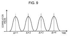
- FIG. 9 is a waveform diagram illustrating an example of the correlation peaks of CDD signals with different delay amounts ( ⁇ 1, ⁇ 2, ⁇ 3, and ⁇ 4) from four transmission branches;
- FIG. 10 is a waveform diagram illustrating exemplary output correlation peaks obtained by receiving the above CDD signals passed through multipath channels by four receiving branches, where FIGS. 10A to 10D show different peaks of the respective reception branches # 1 to # 4 ;
- FIG. 11 is a schematic block diagram illustrating an exemplary configuration of a circuit for synchronizing detection by autocorrelation processing
- FIG. 12 is schematic block diagram illustrating an exemplary configuration of a circuit for synchronizing detection by cross-correlation processing
- FIG. 13 is a schematic block diagram illustrating an exemplary internal configuration of synchronous processing unit 224 ;
- FIG. 14 is a flowchart illustrating an example of processing procedures for detecting synchronous timing based on the results of correlation processing for the respective reception branches;
- FIG. 15 is a flowchart illustrating another example of processing procedures for detecting synchronous timing based on the results of correlation processing for the respective reception branches;
- FIG. 16 is a waveform diagram illustrating how to determine synchronous timing of the reception branch which has not exceeded the threshold at the time of defining synchronous timing according to the processing procedures shown in FIG. 15 , where FIG. 16A shows the peak of a reception branch # 1 , which exceeds the threshold, and FIG. 16B shows the peak of a reception branch # 2 , which does not exceed the threshold;
- FIG. 17 is a schematic block diagram illustrating an exemplary internal configuration of synchronous processing unit 224 , where the finding of a packet by autocorrelation processing and the detection of detailed synchronous timing by subsequent cross-correlation processing are used in combination;
- FIG. 18 is a schematic diagram illustrating an exemplary configuration of a control loop in which a digital domain controls an AGC amplifier 303 .
- FIG. 1 is an exemplary configuration of a computer with a wireless communication function.
- a central processing unit (CPU) 1 executes programs stored in a read only memory (ROM) 2 and a hard disk drive (HDD) 11 in the program execution environment provided by operating system (OS). For example, the CPU 1 may execute a predetermined program to perform synchronous processing of a received packet or processing of part thereof which will be described later.
- the ROM 2 stores program codes such as those of the power on self test (POST) and the basic input/output system (BIOS).
- a random access memory (RAM) 3 is used for loading the program stored in the ROM 2 or the HDD 11 onto the CPU 1 to execute the program or temporarily holding the work data of the program under execution temporarily.
- These structural components are connected to one another through a local bus 4 directly linked with a local pin.
- the local bus 4 is connected to an input-output (I/O) bus, such as a peripheral component interconnect (PCI), through a bridge 5 .
- I/O input-output
- PCI peripheral component interconnect
- Input devices operated by user are a key board 8 and a pointing device (such as a mouse) 8 .
- a display 10 may be a liquid crystal display (LCD) or a cathode ray tube (CRT) to display various kinds on information in text and image.
- LCD liquid crystal display
- CRT cathode ray tube
- the HDD 11 includes a drive unit with a built-in hard disk as a removing medium and drives such a hard disk.
- the hard disk is used for installation of CPU-executable programs such as the operation system and various kinds of applications and storage of data files or the like.
- a communication unit 12 is a wireless communications interface that conforms IEEE 802.11a/n or the like, acting as an access point or a terminal station in infrastructure mode or acting in ad hoc mode to execute communication with another communication terminal in a range of communications.
- each of a transmitter and a receiver on the communication unit 12 has a plurality of antenna elements and adopts the MIMO communication scheme to realize spatial multiplexing streams.
- the transmission branch performs space-time coding on a plurality of transmitted data and distributes the multiplexed data to a plurality of transmission antennas, followed by transmitting the data to a channel.
- the reception branch receives signals from the transmission branch by a plurality of receiving antennas through the channel and performs space-time decoding on the received signals to divide them into a plurality of transmission data.
- the reception branch obtains the original data without any cross talk between streams.
- the MIMO communication scheme can attain an increase in communication speed by extending the capacity of transmission depending on the number of antennas without extending the range of frequencies.
- FIG. 2 illustrates an exemplary configuration of the transmitter on the communication unit 12
- FIG. 3 illustrates an exemplary configuration of the receiver on the communication unit 12 . Both the transmitter and the receiver perform MIMO communication.
- the number of antennas of the transmitter shown in FIG. 2 (or the number of transmission branches) is “M” (“M” is an integer number not less than one (1)). For example, “M” is four (4) at a maximum based on the IEEE specification.
- M is an integer number not less than one (1).
- M is four (4) at a maximum based on the IEEE specification.
- Transmit data supplied from a data generator 100 is scrambled by a scrambler 102 and then subjected to error correction coding by an encoder 104 .
- the scrambling system and the coding system may follow the definitions in the IEEE 802.11a standard.
- the encoded signals are then input in a data distribution unit 106 and then distributed to each of transmission streams.
- a transmission signal is punctured by a puncture 108 according to a data rate applied to each stream and then interleaved by an interleaver 110 . Subsequently, the signal is mapped to an IQ signal space having an in phase (I) and a quadrature phase (Q) by a mapper 112 to obtain a complex baseband signal.
- a selector 111 inserts training series into the transmission signal of each interleaved spatial stream at appropriate timing and then supplies it to a mapper 112 .
- an interleaving scheme expands the definition of IEEE 802.11a, such that the same interleaving is not performed among a plurality of streams. For mapping scheme, BPSK, QPSK, 16 QAM, or 64 QAM is applied according to IEEE 802.11a.
- a transmission weight calculator 114 a constructs a transmit beamforming matrix V from a channel matrix H by a matrix decomposition method such as a singular value decomposition (SVD).
- a transmit beamforming matrix V may be constructed from channel information feed-backed from a communications partner as is well known in the art.
- a transmission weight matrix multiplication unit 114 b multiplies a transmission vector using transmission streams as its elements by this transmission weight matrix V to subject the transmission signal to beamforming.
- the transmission weight matrix multiplication unit 114 b may perform fixed beamforming such as cyclic delay diversity (CDD) where transmission timing between the transmitting branches is provided with a time lag.
- CDD cyclic delay diversity
- An inverse fast Fourier transform unit (IFFT) 116 converts each of sub-carriers arranged in a frequency region into a time axis signal. Furthermore, a guard insertion unit 118 adds a guard interval to the time axis signal. Subsequently, a digital filter 120 performs band limitation and then a digital-analog converter (DAC) 122 converts the band-limited signal into an analog signal.
- a RF unit 124 removes signal components out of a desired bandwidth from the analog signal by the analog LPF, up-converts the center frequency of the signal to a desired RF frequency band, and amplifies the amplitude of the signal by power amplifier. The transmission signal at the RF band is then emitted from each transmission antenna to a space.
- the number of antennas of the transmitter shown in FIG. 3 is “M” (“M” is an integer number not less than one (1)). For example, “M” is four (4) at a maximum based on the IEEE specification.
- the receiver which will be described below, is designed to receive packets transmitted after beamforming processing with different amounts of delay for the respective transmission branches.
- data that reaches the receiver through the channel is analog-processed in an RF unit 230 in each of the reception branch.
- FIG. 4 illustrates an exemplary configuration of the RF unit 230 for each reception branch.
- the RF unit 230 shown in the figure is designed so that the electric power of a received signal will be within the dynamic range of an AD converter (described later).
- the RF unit 230 includes a low noise amplifier (LNA) 301 , an orthogonal demodulator (IQ demodulator) 302 for down conversion of a received signal in the RF frequency band, an AGC amplifier 303 for normalizing the signal, and an analog low-pass filter (LPF) 304 for removing signal components out of a desired bandwidth from the signal.
- LNA low noise amplifier
- IQ demodulator orthogonal demodulator
- AGC amplifier 303 for normalizing the signal
- LPF analog low-pass filter
- An AD converter (ADC) 228 converts the analog received signal into a digital signal and then passes the digital signal to a digital filter 226 . Subsequently, synchronous timing is detected in a synchronous processing unit 224 where several kinds of processing, such as frequency-offset amendment and noise level (or SNR) presumption, are also performed. The detection of synchronous timing is performed by taking autocorrelation or cross-correlation of a known training sequence burstly included at the head of a received packet (described later).
- a guard removing unit 222 a guard interval added to the head of a data transmission interval is removed therefrom. Then, a fast Fourier transform unit (FFT) 220 converts a time axis signal into a frequency axis signal. The following calibration unit 218 multiplies the received signals of the respective reception branches by calibration coefficient for correcting imbalances in phase and amplitude between the reception branches, where the imbalance correction is performed in a digital section (not shown).
- FFT fast Fourier transform unit
- a space division unit 216 performs space division processing of a spatially multiplexed reception signal.
- a channel matrix estimation section 216 a constructs an estimation channel matrix H from a training series for exciting a channel matrix received by each reception branch.
- the estimation channel matrix H may be passed as a backward channel matrix to the transmission weight calculator section 114 a of the transmitter.
- a multiplication section for antenna reception weight matrix (hereinafter, referred to as a reception weight calculator) 216 b calculates an antenna reception weight matrix W based on the channel matrix H obtained by a channel matrix estimation section 216 a .
- An antenna reception weight matrix 216 b multiplies a reception vector having each reception stream as its element by the antenna reception weight matrix W to perform spatial decoding of the spatial multiplexed signal, thereby obtaining independent signal series for each stream.
- a channel equalization circuit 214 performs remaining frequency offset correction and channel tracking with respect to the signal series of each stream.
- a demapper 212 damps the reception signal on the IQ signal space, a deinterleaver 210 performs deinterleaving, and a depuncure 208 performs depuncturing at a predetermined data rate.
- a data synthesis unit 206 combines a plurality of reception streams to make a single stream. Operation completely contrary to the data division which performs this merge process by a transmitting side is performed. And in a decoder 204 , after carrying out an error correction decoding based on likelihood information, it descrambles by a descrambler 202 and data acquiring unit 200 acquires reception data.
- a PHY layer of IEEE 802.11n is provided with a high-throughput (HT) transfer mode (hereinafter referred to as “HT mode”).
- HT mode a high-throughput (HT) transfer mode
- MCS Modulation and Coding Scheme
- the PHY layer is provided with an operation mode wherein data transmission is performed in the same packet format and frequency area as those of IEEE 802.11a/g (hereinafter referred to as “legacy mode”).
- legacy mode an operation mode wherein data transmission is performed in the same packet format and frequency area as those of IEEE 802.11a/g.
- the HT mode is divided into two different operation modes.
- MM mixed mode
- GF green field
- the packet formats in legacy mode and MM mode are shown in FIG. 5 and FIG. 6 , respectively. However, in each figure, a single OFDM symbol presupposes that it is 4 microseconds.
- the format of a packet used in the legacy mode shown in FIG. 5 (hereinafter referred to as a “legacy packet”) is entirely the same as that of IEEE 802.11a/g.
- the header portion of the legacy packet has a legacy preamble.
- the legacy preamble includes: a legacy short training field (L-STF) including a known OFDM symbol provided for finding a packet; a legacy long training field (L-LTF) including a known training symbol provided for performing synchronization acquisition and equalization; and a legacy signal field (L-SIG) on which the transfer rate and/or the data length is written.
- L-STF legacy short training field
- L-LTF legacy long training field
- L-SIG legacy signal field
- the header portion of a packet shown in FIG. 6 includes: a legacy preamble generated in a format which is entirely the same as that used for IEEE 802.11a/g; a subsequent preamble generated in a format which is typically used for IEEE 802.11n (hereinafter referred to as an “HT format”) (hereinafter referred to as an “HT preamble”); and a data portion.
- a legacy preamble generated in a format which is entirely the same as that used for IEEE 802.11a/g a subsequent preamble generated in a format which is typically used for IEEE 802.11n (hereinafter referred to as an “HT preamble”); and a data portion.
- the portion corresponding to a PHY payload in the legacy packet is formed in HT format.
- the HT preamble and the PHY payload may be provided in HT format.
- the HT preamble includes an HT-SIG, an HT-STF, and an HT-LTF.
- the HT-SIG describes information necessary to understand the HT format, such as information about an MCS and/or the payload-data length used for the PHY payload (PSDU).
- the HT-STF includes a training symbol provided for improvement of automatic-gain control (AGC) in a MIMO system.
- the HT-LTF includes a training symbol provided for performing channel estimation for every input signal subjected to spatial modulation (mapping) in the receiver.
- the receiver has to acquire a channel matrix by performing channel estimation for every transmission/reception antenna performing spatial separation for a reception signal. Therefore, the transmitter is designed to transmit the HT-LTF from each of transmission antennas to the receiver in a time-division manner. Subsequently, at least one HT-LTF field is added according to the spatial-stream number.
- the legacy preamble provided in the MM packet is generated in a format which is entirely the same as that of the preamble of the legacy packet and transferred in a transfer scheme so that the legacy terminal can decode the legacy preamble.
- the HT-format portion that comes after the HT preamble is transferred in a transfer method that is not supported by the legacy terminal.
- the legacy terminal decodes the L-SIG included in the legacy preamble of the MM packet. Then, the legacy terminal reads information showing that the MM packet is not addressed to itself, data-length information, and so on.
- the legacy terminal sets a network allocation vector (NAV) of an appropriate length, a transmission-wait-time interval, to avoid a collision. As a result, the MM packet can achieve compatibility with the legacy terminal.
- NAV network allocation vector
- FIG. 7 illustrates the configuration of a legacy preamble.
- a short preamble interval of 8.0 microseconds STF: short training field
- a long preamble interval of 8.0 microseconds LTF: long training field
- the short preamble interval is formed of a short training sequence (STS), in which ten short preamble symbols t 1 to t 10 are transmitted in a burst manner, or repeatedly transmitted 10 times.
- STS short training sequence
- the long preamble interval is formed of a long training sequence (LTS), in which two long preamble symbols T 1 to T 2 are repeatedly transmitted twice after a guard interval GI 2 of 1.6 microseconds.
- the receiver can determine synchronous timing (coarse) by taking autocorrelation between known short training sequences STSs repeatedly occurred in STF and finding that the absolute value (the square thereof) of the autocorrelation exceeds a predetermined threshold.
- a receiver sets the ACG gain of the receiver and corrects a DC offset using four STS symbols of 0.8 ⁇ s, and performs frequency-offset estimation and correction, packet detection, and coarse timing detection using the remaining six STS symbols.
- packet detection is used as a trigger
- the remaining preamble intervals are used for performing timing detection, frequency-offset measurement, digital gain control, and so on (see, for example, Japanese Published Patent Application No. 2004-221940 (paragraph Nos. 0158 to 0164 and FIG. 29 ).
- cross-correlation with a known signal in the L-LTF interval subsequent to the L-STF is determined and synchronous timing (detailed) is then detected on the basis of the resulting peak.
- FIG. 8 illustrates the data structure of the HT-SIG filed.
- the HT-SIG field is constructed of two OFDM symbols, HT-SIG 1 ( FIG. 8A ) and HT-SIG 2 ( FIG. 8B ), describing information necessary for interpreting the HT format including MCS (described later) used for the PHY payload (PSDU), the data length of the payload, and so on. Irrespective of whether the MM packet or the GF packet is used, the details of the information written in the HT-SIG field are one and the same.
- the preamble portion including the HT-SIG field is arranged so that the BPSK modulation with an encoding rate of 1 ⁇ 2 is used for both the legacy preamble and an HT preamble.
- the use of low data rate as described above ensures processing and/or information notification necessary for performing the packet reception.
- an unexpected beam may be formed when identical or similar signals are transmitted through different space streams. For this reason, as described above, a method of transmitting a time-difference signal from each transmission antenna, CDD, is employed.
- the number of spatial streams N ss can be specified as described below in addition to obtain information about a transfer method to be applied to the HT field on the basis of the value of a modulation and coding scheme (MCS) in the first symbol of control information in the head portion of the HT packet (HT-SIG 1 ).
- MCS modulation and coding scheme
- the delay amount (cyclic shift value) of transmission timing between transmission antennas can be identified from the number of spatial streams N ss with respect to each of the legacy preamble part and the HT format part of the MM packet.
- the second spatial stream in the legacy preamble part includes a time-difference signal with a delay amount of ⁇ 200 nanoseconds (ns) with respect to the first spatial stream.
- a plurality of correlation peaks will appear when a signal with CDD (i.e., a signal with a different delay amount for each transmission antenna) is subjected to synchronous processing in the receiver. Therefore, if the synchronous timing is obtained by averaging or weighted averaging of the correlation value of the reception branch, erroneous detection probability may be increased depending on a channel or receiving environment.
- signal levels received by the receiver through a plurality of antennas may have significant variations due to multipath fading. Therefore, if each of the reception branches is adapted to the minimum or maximum reception gain, an extremely large dynamic range will be necessary for the subsequent reception operation.
- FIG. 9 illustrates an example of the correlation peaks of CDD signals with different delay amounts ( ⁇ 1, ⁇ 2, ⁇ 3, and ⁇ 4) from four transmission branches, which are represented in the undermost row of Table 1 as described above.
- FIG. 10 illustrates exemplary output correlation peaks obtained by receiving the above CDD signals passed through multipath channels by four reception branches.
- FIG. 10A to FIG. 10D illustrate different output correlation peaks obtained in the respective reception branches # 1 to # 4 .
- the correlation values for signals passed through the actual MIMO transmission path have different correlation peaks for the respective reception branches. If the phases of the correlation peaks for the respective reception branches are significantly different from one another, averaging or weighted averaging of the correlation values of the reception branches is inefficient.
- the present inventors consider that an improvement in detection accuracy will be obtained by independently detecting synchronous timing if there is a large difference in phase of correlation peak among the reception branches. Even if processing is performed with different synchronous timing for each reception branch, there is no substantial effect on the subsequent receiving processing just as in the case with the use of common synchronous timing in the respective reception branches.
- FIG. 11 illustrates an exemplary configuration of a circuit for synchronizing detection by correlation processing, which is arranged in each reception branch.
- the example shown in the figure is designed to perform autocorrelation processing is performed using an L-STF interval, but not limited thereto.
- a delay unit 601 holds a received signal with repetitive periodic intervals of a known training sequence burstly added to the head of a packet and outputs such a signal as a delay signal.
- a complex conjugate unit 602 takes the complex conjugate of this delay signal.
- a multiplier unit 603 performs complex conjugate multiplication between the received signal and the delay signal per repetitive periodic interval (0.8 microseconds) of the known training sequence.
- An averaging unit 604 calculates the moving average of products output from the multiplier unit 603 for a predetermined moving average section to find an autocorrelation value. Subsequently, a judging unit 606 finds out a packet at a time when the autocorrelation value exceeds the predetermined threshold. As a result, synchronous timing is obtained.
- X is an integer of one or more.
- an autocorrelation value which is the peak value or the maximum value may be determined as synchronous timing.
- the synchronous processing unit 224 determines that the packet synchronization is attained when the autocorrelation results of a predetermined number X of the received branches exceed a threshold value.
- a peak detection window within ⁇ y[samples] from the synchronous timing of the branch that exceeds the threshold is formed and an autocorrelation value which is the peak value or the maximum value may be determined as synchronous timing.
- FIG. 12 illustrates an exemplary configuration of a circuit for synchronizing detection by correlation processing, which is arranged in each reception branch.
- the example shown in the figure is designed to perform cross-correlation processing is performed using an L-LTF interval, but not limited thereto.
- a delay unit 701 is constructed of a plurality of delay elements respectively having delay times equivalent to sample cycles and connecting to one another in series, thereby providing the delay time of a timing estimation period as a whole.
- a preamble holding unit 700 holds patterns of a known training sequence LTS defined by standard.
- received signal samples are delayed every sample in each delay element of the delay unit 701 and each of the delayed signal is then multiplied by the pattern held in the preamble holding unit 700 .
- a totalizing unit 503 sums up the results of the multiplication to find an inner product, thereby obtaining a cross-correlation value.
- a peak detection unit 704 outputs the peak position of the cross-correlation function as synchronous timing in the reception branch.
- a threshold value when the synchronous processing unit 224 performs correlation processing using a known training sequence of a time waveform at a preamble interval, it is determined that packet synchronization is attained (“X” is an integer of one or more).
- a cross-correlation value which is the peak value or the maximum value may be determined as synchronous timing.
- the synchronous processing unit 224 determines that the packet synchronization is attained when the cross-correlation results of a predetermined number X of the received branches exceed a threshold value.
- a peak detection window within ⁇ y[samples] from the synchronous timing of the branch that exceeds the threshold is formed and a cross-correlation value which is the peak value or the maximum value may be determined as synchronous timing.
- the MIMO receiver shown in FIG. 3 is designed so that the synchronous processing unit 224 may detect synchronous timing from received signals from the respective reception branch after AD conversion.
- the synchronous processing unit 224 includes correlation arithmetic sections 801 shown in FIG. 11 or FIG. 12 which are arranged in parallel for the respective branches.
- a summary section 802 determines whether packet synchronization is attained on the basis of the outputs from the respective correlation arithmetic sections 801 (on the basis of the number of reception branches where the correlation results exceed the threshold).
- FIG. 14 illustrates a flowchart that represents an example of processing procedures for detecting synchronous timing based on the results of correlation processing for the respective reception branches in the synchronous processing unit 224 shown in FIG. 13 .
- each of correlation arithmetic sections 801 provided for the respective reception branches carries out the correlation processing using a known training sequence of a time waveform at a preamble interval, independently from one another (Step S 1 ).
- the summary section 802 determines whether all correlation values obtained by the “N” reception branches have respectively exceeded the threshold (Step S 2 ).
- Step S 3 If all the correlation values obtained by “N” reception branches have not exceeded the threshold (“NO” in Step S 2 ), a timer is started (Step S 3 ). Until the timer is timed out (“NO” in Step S 4 ), the process returns to step S 2 and the summary section 802 continues totalizing the correlation values from the respective reception branches.
- Step S 6 the receiver carries out subsequent processing such as data decoding.
- Step S 4 the acquisition of synchronous timing is given up in the synchronous processing unit 224 .
- the receiver concerned returns to an initial state (Step S 6 ), and enters a standby state until the next packet is arrived.
- the synchronous timing is established when all the correlation values calculated by the respective reception branches exceed the threshold.
- FIG. 15 illustrates a flowchart that represents another example of processing procedures for detecting synchronous timing based on the results of correlation processing for the respective reception branches in the synchronous processing unit 224 shown in FIG. 13 .
- each of correlation arithmetic sections 801 provided for the respective reception branches carries out the correlation processing using a known training sequence of a time waveform at a preamble interval, independently from one another (Step S 11 ).
- the summary section 802 determines whether the correlation values obtained by “X” or more reception branches among “N” reception branches have exceeded the threshold (Step S 12 ).
- Step S 12 if the correlation values obtained by “X” or more reception branches among “N” reception branches have exceeded the threshold (“NO” in Step S 12 ), the timer is started (Step S 13 ). Until the timer is timed out (“NO” in Step S 14 ), the process returns to step S 2 and the summary section 802 continues totalizing the correlation values from the respective reception branches.
- Step S 16 the receiver carries out subsequent processing such as data decoding.
- Step S 12 the number of reception branches where the obtained correlation values thereof exceed the threshold does not reach “X” (“NO” in Step S 12 ) and the timer is timed out (“YES” in Step S 14 ), then the acquisition of synchronous timing is given up in the synchronous processing unit 224 . As a result, the receiver concerned returns to an initial state (Step S 16 ), and enters a standby state until the next packet is arrived.
- the synchronous timing is established when the correlation values calculated by some of the reception branches exceed the threshold.
- a cross-correlation value which is the peak value or the maximum value may be determined as synchronous timing.
- a peak detection window within ⁇ y[samples] from the synchronous timing of the branch that exceeds the threshold is formed and a cross-correlation value which is the peak value or the maximum value may be determined as synchronous timing.
- FIG. 16 how to determine synchronous timing of the reception branch which has not exceeded the threshold is shown in FIG. 16 .
- the detection of synchronous timing is performed based on correlation processing, or either of autocorrelation processing (see FIG. 11 ) or cross-correlation processing (see FIG. 12 ), for each of the reception branches in the synchronous processing unit 224 .
- the detection of synchronous timing may be performed using a combination of these kinds of processing such that the detection of coarse synchronous timing is performed by the autocorrelation processing (finding a packet) and the detection of detailed synchronous timing is then performed by the cross-correlation processing.
- the finding of the packet initiates the latter cross-correlation processing.
- FIG. 17 illustrates an exemplary internal configuration of synchronous processing unit 224 in which the finding of a packet by autocorrelation processing and the detection of detailed synchronous timing by subsequent cross-correlation processing are used in combination.
- the synchronous processing unit 224 includes autocorrelation arithmetic sections 1201 for the respective reception branches and cross-correlation arithmetic sections 1203 for the respective reception branches.
- the autocorrelation arithmetic sections 1201 performs autocorrelation processing using a known training sequence STS of a time waveform at the L-STF interval.
- the cross-correlation arithmetic sections 1203 performs cross-correlation processing using a known training sequence LTS of a time waveform at the L-LTF interval.
- a first summary section 1202 validates an identifying signal for the packet finding based on the summarized results of autocorrelation values of the respective reception branches. For example, it may validate the identifying signal for the packet finding when the autocorrelation results of a predetermined number X of the received branches exceed a threshold value.
- the cross-correlation arithmetic section 1203 for each reception branch is initiated in response to the validated identifying signal and then carries out the cross-correlation processing using LTS of a time waveform of the L-LTF section.
- a second summary section 1204 performs the detection of detailed timing based on the summarized results of cross-correlation values of the respective reception branches. For example, the synchronous processing unit 224 determines that the packet synchronization is attained when the cross-correlation results of a predetermined number X of the received branches exceed a threshold value. However, in the case of a receiving branch which does not exceed the threshold, a peak detection window within ⁇ y[samples] from the synchronous timing of the branch that exceeds the threshold is formed. Then, a cross-correlation value which is the peak value or the maximum value is determined as synchronous timing.
- the AGC control may be independently performed on each reception branch to overcome a problem in that the minimum and maximum reception gains may have significant variations between the reception branches due to multipath fading. Comparing with a case where the AGC control is commonly performed in all the reception branches, an effect of suppressing the dynamic range of an AD converter is expectable.
- FIG. 18 is an exemplary configuration of a control loop in which a digital domain controls an AGC amplifier 303 .
- the AGC control illustrated in the figure is performed in each of the reception branches.
- a received signal is converted into a digital signal by AD converter (ADC) 228 and then subjected to gain control.
- a gain controller 1301 calculates an amplification degree in the AGC amplifier based on the amplitude of the received signal. Received power is calculated from the amplitude of the received signal.
- the digital signal is reconverted into an analog signal by a digital-analog converter (DAC) 1302 .
- DAC digital-analog converter
- the analog signal is then passed through an analog low-pass filter (LPF) 1303 . Subsequently, the signal is fed back to the AGC amplifier 303 .
- LPF analog low-pass filter
- the subsequent decoding processing should hold the gain ratio of the branches. That is, the setting gain ratio between the reception branches when performing AGC is memorized in advance. A final estimated value is obtained in consideration of a fixed gain ratio between the reception branches when various estimated values for each reception branch are averaged or subjected to weighted averaging depending on likelihood.
- the gist of the present invention is not limited thereto.
- the present invention is applicable similarly to various wireless communication systems which adopt the MIMO communication system.
- wireless-communication systems examples include Mobile WiMax (worldwide interoperability for microwave) based on IEEE 802.16e, IEEE 802.20 which is a mobile-oriented high-speed-wireless-communications standard, high-speed wireless PAN (personal area network) standard which uses a 60 GHz (millimeter wave) band, wireless HD which enables transmission of incompressible HD (High Definition) image using wireless transmission of 60 GHz (millimeter wave) band, and fourth generation (4G) cellular phone.
- Mobile WiMax worldwide interoperability for microwave
- IEEE 802.20 which is a mobile-oriented high-speed-wireless-communications standard
- high-speed wireless PAN personal area network
- wireless HD which enables transmission of incompressible HD (High Definition) image using wireless transmission of 60 GHz (millimeter wave) band
- 4G fourth generation
Landscapes
- Engineering & Computer Science (AREA)
- Signal Processing (AREA)
- Computer Networks & Wireless Communication (AREA)
- Radio Transmission System (AREA)
- Mobile Radio Communication Systems (AREA)
Abstract
Description
MCS 0 to 7=>N=1
MCS 24 to 31=>Nss=4
MCS 33 to 38=>Nss=2
MCS 39 to 52=>Nss=3
MCS 53 to 76=>Nss=4
| TABLE 1 |
| Delay amount of transmission timing of legacy part |
| Delay | Delay | Delay | Delay | ||
| Number of | amount of | amount of | amount of | amount of | |
| transmission | transmission | transmission | transmission | transmission | |
| | branch # | 1 | |
|
|
| 1 | 0 ns | — | — | — | |
| 2 | 0 ns | −200 ns | — | — | |
| 3 | 0 ns | −100 ns | −200 ns | — | |
| 4 | 0 ns | −500 ns | −100 ns | −150 ns | |
| TABLE 2 |
| Delay amount of transmission timing of HT part |
| Number of | Delay | Delay | Delay | Delay | |
| spatial | amount of | amount of | amount of | amount of | |
| | stream # | 1 | |
|
|
| 1 | 0 ns | — | — | — | |
| 2 | 0 ns | −400 ns | — | — | |
| 3 | 0 ns | −400 ns | −200 ns | — | |
| 4 | 0 ns | −400 ns | −200 ns | −600 ns | |
Claims (9)
Applications Claiming Priority (2)
| Application Number | Priority Date | Filing Date | Title |
|---|---|---|---|
| JP2008263960A JP4636162B2 (en) | 2008-10-10 | 2008-10-10 | Wireless communication apparatus and wireless communication method |
| JP2008-263960 | 2008-10-10 |
Publications (2)
| Publication Number | Publication Date |
|---|---|
| US20100091911A1 US20100091911A1 (en) | 2010-04-15 |
| US8331518B2 true US8331518B2 (en) | 2012-12-11 |
Family
ID=42098836
Family Applications (1)
| Application Number | Title | Priority Date | Filing Date |
|---|---|---|---|
| US12/555,267 Expired - Fee Related US8331518B2 (en) | 2008-10-10 | 2009-09-08 | Wireless communication apparatus for receiving packets transmitted with delay amounts different for respective transmission branches |
Country Status (3)
| Country | Link |
|---|---|
| US (1) | US8331518B2 (en) |
| JP (1) | JP4636162B2 (en) |
| CN (1) | CN101729120B (en) |
Cited By (3)
| Publication number | Priority date | Publication date | Assignee | Title |
|---|---|---|---|---|
| US20210007092A1 (en) * | 2015-02-12 | 2021-01-07 | Huawei Technologies Co., Ltd. | System and Method for Auto-Detection of WLAN Packets using STF |
| US11777548B1 (en) * | 2022-05-12 | 2023-10-03 | Silicon Laboratories Inc. | Context switching demodulator and symbol identifier |
| US12219599B2 (en) | 2022-05-12 | 2025-02-04 | Silicon Laboratories Inc. | Concurrent listening |
Families Citing this family (18)
| Publication number | Priority date | Publication date | Assignee | Title |
|---|---|---|---|---|
| JP5564282B2 (en) * | 2010-02-16 | 2014-07-30 | パナソニック株式会社 | Receiver circuit and receiver |
| CN103069733A (en) * | 2010-09-28 | 2013-04-24 | 三洋电机株式会社 | Receiving device |
| JP5644370B2 (en) * | 2010-10-27 | 2014-12-24 | 日本電気株式会社 | Radio transmission apparatus, radio reception apparatus, clock synchronization method, and radio communication system |
| JP5935044B2 (en) | 2011-01-27 | 2016-06-15 | パナソニックIpマネジメント株式会社 | Receiver |
| US9385911B2 (en) | 2011-05-13 | 2016-07-05 | Sameer Vermani | Systems and methods for wireless communication of packets having a plurality of formats |
| US9154363B2 (en) * | 2011-05-13 | 2015-10-06 | Qualcomm Incorporated | Systems and methods for wireless communication of packets having a plurality of formats |
| KR101656083B1 (en) * | 2011-09-15 | 2016-09-09 | 한국전자통신연구원 | Apparatus and method for obtaining reception synchronization in wireless communication system |
| US9088504B2 (en) | 2012-01-06 | 2015-07-21 | Qualcomm Incorporated | Systems and methods for wireless communication of long data units |
| TWI491194B (en) * | 2012-02-21 | 2015-07-01 | Mstar Semiconductor Inc | Method and associated apparatus for determining signal timing of wireless network signal |
| CN103378897B (en) * | 2012-04-23 | 2017-12-22 | 中兴通讯股份有限公司 | Realize the method and device of CMMB diversity reception |
| US9060338B2 (en) * | 2013-03-14 | 2015-06-16 | Qualcomm Incorporated | Method and apparatus for switching between low-power, single-chain listen and multiple-chain demodulation |
| US9787517B2 (en) * | 2013-04-01 | 2017-10-10 | Harman International Industries, Incorporated | Coarse timing |
| EP3116271B1 (en) * | 2014-04-02 | 2020-06-03 | Huawei Technologies Co. Ltd. | Signal transmission method and apparatus |
| CN105323033A (en) * | 2014-06-30 | 2016-02-10 | 深圳市中兴微电子技术有限公司 | Multipath frame header detection method and device |
| US9854552B2 (en) * | 2015-06-16 | 2017-12-26 | National Instruments Corporation | Method and apparatus for improved Schmidl-Cox-based signal detection |
| US10333693B2 (en) | 2016-12-09 | 2019-06-25 | Micron Technology, Inc. | Wireless devices and systems including examples of cross correlating wireless transmissions |
| US10298335B1 (en) * | 2017-10-31 | 2019-05-21 | Huawei Technologies Co., Ltd. | Co-channel interference reduction in mmWave networks |
| US12206533B2 (en) * | 2022-07-13 | 2025-01-21 | Nxp Usa, Inc. | Non-long range preamble design for long range wireless packet and methods for processing the preamble |
Citations (13)
| Publication number | Priority date | Publication date | Assignee | Title |
|---|---|---|---|---|
| JP2000354020A (en) | 1999-06-10 | 2000-12-19 | Matsushita Electric Ind Co Ltd | Receiver |
| US20030012267A1 (en) * | 2000-03-06 | 2003-01-16 | Daisuke Jitsukawa | CDMA receiver, and searcher in a CDMA receiver |
| US20030072255A1 (en) | 2001-10-17 | 2003-04-17 | Jianglei Ma | System access and synchronization methods for MIMO OFDM communications systems and physical layer packet and preamble design |
| US20050276347A1 (en) | 2004-06-10 | 2005-12-15 | Mujtaba Syed A | Method and apparatus for preamble training in a multiple antenna communication system |
| JP2006005390A (en) | 2004-06-15 | 2006-01-05 | Hitachi Ltd | Synchronization acquisition method, synchronization signal generation method, and communication apparatus |
| JP2006042075A (en) | 2004-07-28 | 2006-02-09 | Sony Corp | Wireless communication apparatus, wireless communication method, and computer program |
| JP2006217248A (en) | 2005-02-03 | 2006-08-17 | Toshiba Corp | Reception apparatus and symbol synchronization timing detection method |
| JP2007013627A (en) | 2005-06-30 | 2007-01-18 | Toshiba Corp | Wireless communication device |
| US20070189263A1 (en) | 2006-02-14 | 2007-08-16 | Sony Corporation | Wireless communication apparatus and wireless communication method |
| JP2007306342A (en) | 2006-05-11 | 2007-11-22 | Toyota Industries Corp | Diversity control method |
| JP2008530909A (en) | 2005-02-09 | 2008-08-07 | アギア システムズ インコーポレーテッド | Method and apparatus for preamble training with shortened long training field in multi-antenna communication system |
| US20090011714A1 (en) * | 2007-07-05 | 2009-01-08 | Fujitsu Limited | Communication apparatus and method for controlling diversity reception |
| EP2043281A1 (en) * | 2007-01-12 | 2009-04-01 | Panasonic Corporation | Reception device and reception method |
Family Cites Families (1)
| Publication number | Priority date | Publication date | Assignee | Title |
|---|---|---|---|---|
| CN101174925A (en) * | 2006-10-31 | 2008-05-07 | 株式会社Ntt都科摩 | Method, system, base station and user equipment for determining cyclic delay diversity delay value |
-
2008
- 2008-10-10 JP JP2008263960A patent/JP4636162B2/en not_active Expired - Fee Related
-
2009
- 2009-09-08 US US12/555,267 patent/US8331518B2/en not_active Expired - Fee Related
- 2009-10-10 CN CN200910204696.9A patent/CN101729120B/en not_active Expired - Fee Related
Patent Citations (17)
| Publication number | Priority date | Publication date | Assignee | Title |
|---|---|---|---|---|
| JP2000354020A (en) | 1999-06-10 | 2000-12-19 | Matsushita Electric Ind Co Ltd | Receiver |
| US20030012267A1 (en) * | 2000-03-06 | 2003-01-16 | Daisuke Jitsukawa | CDMA receiver, and searcher in a CDMA receiver |
| US20030072255A1 (en) | 2001-10-17 | 2003-04-17 | Jianglei Ma | System access and synchronization methods for MIMO OFDM communications systems and physical layer packet and preamble design |
| JP2005506757A (en) | 2001-10-17 | 2005-03-03 | ノーテル・ネットワークス・リミテッド | Synchronization in multi-carrier CDMA systems |
| JP2008503180A (en) | 2004-06-10 | 2008-01-31 | アギア システムズ インコーポレーテッド | Method and apparatus for preamble training in a multi-antenna communication system |
| US20050276347A1 (en) | 2004-06-10 | 2005-12-15 | Mujtaba Syed A | Method and apparatus for preamble training in a multiple antenna communication system |
| JP2006005390A (en) | 2004-06-15 | 2006-01-05 | Hitachi Ltd | Synchronization acquisition method, synchronization signal generation method, and communication apparatus |
| JP2006042075A (en) | 2004-07-28 | 2006-02-09 | Sony Corp | Wireless communication apparatus, wireless communication method, and computer program |
| JP2006217248A (en) | 2005-02-03 | 2006-08-17 | Toshiba Corp | Reception apparatus and symbol synchronization timing detection method |
| JP2008530909A (en) | 2005-02-09 | 2008-08-07 | アギア システムズ インコーポレーテッド | Method and apparatus for preamble training with shortened long training field in multi-antenna communication system |
| US20090122882A1 (en) | 2005-02-09 | 2009-05-14 | Mujtaba Syed A | Method and apparatus for preamble training with shortened long training field in a multiple antenna communication system |
| JP2007013627A (en) | 2005-06-30 | 2007-01-18 | Toshiba Corp | Wireless communication device |
| US20070189263A1 (en) | 2006-02-14 | 2007-08-16 | Sony Corporation | Wireless communication apparatus and wireless communication method |
| JP2007221187A (en) | 2006-02-14 | 2007-08-30 | Sony Corp | Wireless communication apparatus and wireless communication method |
| JP2007306342A (en) | 2006-05-11 | 2007-11-22 | Toyota Industries Corp | Diversity control method |
| EP2043281A1 (en) * | 2007-01-12 | 2009-04-01 | Panasonic Corporation | Reception device and reception method |
| US20090011714A1 (en) * | 2007-07-05 | 2009-01-08 | Fujitsu Limited | Communication apparatus and method for controlling diversity reception |
Non-Patent Citations (1)
| Title |
|---|
| Office Action issued Aug. 3, 2010 in JP Application No. 2008-263960. |
Cited By (5)
| Publication number | Priority date | Publication date | Assignee | Title |
|---|---|---|---|---|
| US20210007092A1 (en) * | 2015-02-12 | 2021-01-07 | Huawei Technologies Co., Ltd. | System and Method for Auto-Detection of WLAN Packets using STF |
| US11637572B2 (en) * | 2015-02-12 | 2023-04-25 | Huawei Technologies Co., Ltd. | Method for auto-detection of WLAN packets using STF |
| US12155399B2 (en) | 2015-02-12 | 2024-11-26 | Huawei Technologies Co., Ltd. | Method for auto-detection of WLAN packets using STF |
| US11777548B1 (en) * | 2022-05-12 | 2023-10-03 | Silicon Laboratories Inc. | Context switching demodulator and symbol identifier |
| US12219599B2 (en) | 2022-05-12 | 2025-02-04 | Silicon Laboratories Inc. | Concurrent listening |
Also Published As
| Publication number | Publication date |
|---|---|
| CN101729120B (en) | 2014-10-22 |
| JP2010093703A (en) | 2010-04-22 |
| US20100091911A1 (en) | 2010-04-15 |
| CN101729120A (en) | 2010-06-09 |
| JP4636162B2 (en) | 2011-02-23 |
Similar Documents
| Publication | Publication Date | Title |
|---|---|---|
| US8331518B2 (en) | Wireless communication apparatus for receiving packets transmitted with delay amounts different for respective transmission branches | |
| JP4572968B2 (en) | Packet detection device, packet detection method, wireless communication device, wireless communication method, and computer program | |
| JP4666031B2 (en) | Synchronous circuit and wireless communication device | |
| US8289869B2 (en) | Wireless communication system, wireless communication device and wireless communication method, and computer program | |
| US8737189B2 (en) | Method and system for compromise greenfield preambles for 802.11n | |
| US8077696B2 (en) | Wireless communication apparatus and wireless communication method | |
| CA2773681C (en) | Method and apparatus of transmitting training signal in wireless local area network system | |
| JP4544349B2 (en) | Wireless communication apparatus, wireless communication method, and computer program | |
| JP5702387B2 (en) | Signaling and channel estimation for uplink transmit diversity | |
| US8111608B2 (en) | Radio-communication device and radio-communication method | |
| US8452240B2 (en) | Radio communication device, radio communication system, and radio communication method | |
| US7660288B2 (en) | Radio communication device | |
| TWI873234B (en) | Link adaptation using transmission rate options | |
| US8761273B2 (en) | Method for transmitting and receiving wireless signal in wireless communication system and apparatus for the same | |
| US8228894B2 (en) | Synchronization circuit, synchronization method, wireless communication apparatus, wireless communication method, and computer program | |
| US11570654B2 (en) | Link adaptation using a link quality estimation sequence | |
| CN101142760A (en) | Antenna selection diversity apparatus and method in a broadband wireless communication system |
Legal Events
| Date | Code | Title | Description |
|---|---|---|---|
| AS | Assignment |
Owner name: SONY CORPORATION,JAPAN Free format text: ASSIGNMENT OF ASSIGNORS INTEREST;ASSIGNORS:SAWAI, RYOU;TAKAHASHI, HIROAKI;SIGNING DATES FROM 20090826 TO 20090828;REEL/FRAME:023203/0207 Owner name: SONY CORPORATION, JAPAN Free format text: ASSIGNMENT OF ASSIGNORS INTEREST;ASSIGNORS:SAWAI, RYOU;TAKAHASHI, HIROAKI;SIGNING DATES FROM 20090826 TO 20090828;REEL/FRAME:023203/0207 |
|
| ZAAA | Notice of allowance and fees due |
Free format text: ORIGINAL CODE: NOA |
|
| ZAAB | Notice of allowance mailed |
Free format text: ORIGINAL CODE: MN/=. |
|
| STCF | Information on status: patent grant |
Free format text: PATENTED CASE |
|
| FEPP | Fee payment procedure |
Free format text: PAYOR NUMBER ASSIGNED (ORIGINAL EVENT CODE: ASPN); ENTITY STATUS OF PATENT OWNER: LARGE ENTITY |
|
| FPAY | Fee payment |
Year of fee payment: 4 |
|
| MAFP | Maintenance fee payment |
Free format text: PAYMENT OF MAINTENANCE FEE, 8TH YEAR, LARGE ENTITY (ORIGINAL EVENT CODE: M1552); ENTITY STATUS OF PATENT OWNER: LARGE ENTITY Year of fee payment: 8 |
|
| FEPP | Fee payment procedure |
Free format text: MAINTENANCE FEE REMINDER MAILED (ORIGINAL EVENT CODE: REM.); ENTITY STATUS OF PATENT OWNER: LARGE ENTITY |
|
| LAPS | Lapse for failure to pay maintenance fees |
Free format text: PATENT EXPIRED FOR FAILURE TO PAY MAINTENANCE FEES (ORIGINAL EVENT CODE: EXP.); ENTITY STATUS OF PATENT OWNER: LARGE ENTITY |
|
| STCH | Information on status: patent discontinuation |
Free format text: PATENT EXPIRED DUE TO NONPAYMENT OF MAINTENANCE FEES UNDER 37 CFR 1.362 |
|
| FP | Lapsed due to failure to pay maintenance fee |
Effective date: 20241211 |