US8328365B2 - Mesh for mapping domains based on regularized fiducial marks - Google Patents
Mesh for mapping domains based on regularized fiducial marks Download PDFInfo
- Publication number
- US8328365B2 US8328365B2 US12/433,565 US43356509A US8328365B2 US 8328365 B2 US8328365 B2 US 8328365B2 US 43356509 A US43356509 A US 43356509A US 8328365 B2 US8328365 B2 US 8328365B2
- Authority
- US
- United States
- Prior art keywords
- fiducial marks
- quadrilateral
- image
- domain
- display surface
- Prior art date
- Legal status (The legal status is an assumption and is not a legal conclusion. Google has not performed a legal analysis and makes no representation as to the accuracy of the status listed.)
- Expired - Fee Related, expires
Links
- 238000013507 mapping Methods 0.000 title claims description 43
- 238000000034 method Methods 0.000 claims abstract description 78
- 238000009499 grossing Methods 0.000 claims abstract description 17
- 239000000872 buffer Substances 0.000 claims description 29
- 238000005259 measurement Methods 0.000 claims description 7
- 238000001514 detection method Methods 0.000 claims description 5
- 230000001788 irregular Effects 0.000 claims description 5
- 238000003860 storage Methods 0.000 claims description 4
- 238000012937 correction Methods 0.000 description 29
- 230000006870 function Effects 0.000 description 17
- 238000010586 diagram Methods 0.000 description 15
- 238000012545 processing Methods 0.000 description 14
- 238000009877 rendering Methods 0.000 description 7
- 239000011159 matrix material Substances 0.000 description 5
- 230000009466 transformation Effects 0.000 description 4
- 239000013598 vector Substances 0.000 description 3
- 238000005452 bending Methods 0.000 description 2
- 238000006243 chemical reaction Methods 0.000 description 2
- 230000006837 decompression Effects 0.000 description 2
- 239000003550 marker Substances 0.000 description 2
- 238000000926 separation method Methods 0.000 description 2
- 230000000007 visual effect Effects 0.000 description 2
- 230000006978 adaptation Effects 0.000 description 1
- 230000000694 effects Effects 0.000 description 1
- 238000003702 image correction Methods 0.000 description 1
- 238000012432 intermediate storage Methods 0.000 description 1
- 239000000463 material Substances 0.000 description 1
- 230000010355 oscillation Effects 0.000 description 1
- 238000003909 pattern recognition Methods 0.000 description 1
- 230000002085 persistent effect Effects 0.000 description 1
- 238000010845 search algorithm Methods 0.000 description 1
Images


Classifications
-
- H—ELECTRICITY
- H04—ELECTRIC COMMUNICATION TECHNIQUE
- H04N—PICTORIAL COMMUNICATION, e.g. TELEVISION
- H04N9/00—Details of colour television systems
- H04N9/12—Picture reproducers
-
- H—ELECTRICITY
- H04—ELECTRIC COMMUNICATION TECHNIQUE
- H04N—PICTORIAL COMMUNICATION, e.g. TELEVISION
- H04N9/00—Details of colour television systems
- H04N9/12—Picture reproducers
- H04N9/31—Projection devices for colour picture display, e.g. using electronic spatial light modulators [ESLM]
- H04N9/3141—Constructional details thereof
- H04N9/3147—Multi-projection systems
Definitions
- Planar images captured by such cameras may be reproduced onto planar surfaces.
- planar images captured by such cameras may be reproduced onto planar surfaces.
- the viewer When a viewer views a planar image that has been reproduced onto a planar surface, the viewer generally perceives the image as being undistorted, assuming no keystone distortion, even when the viewer views the image at oblique angles to the planar surface of the image. If a planar image is reproduced onto a non-planar surface (e.g., a curved surface) without any image correction, the viewer generally perceives the image as being distorted.
- a non-planar surface e.g., a curved surface
- Display systems that reproduce images in tiled positions may provide immersive visual experiences for viewers. While tiled displays may be constructed from multiple, abutting display devices, these tiled displays generally produce undesirable seams between the display devices that may detract from the experience. In addition, because these display systems generally display planar images, the tiled images may appear distorted and unaligned if displayed on a non-planar surface without correction. In addition, the display of the images with multiple display devices may be inconsistent because of the display differences between the devices.
- One embodiment provides a method that includes capturing a first image of a display surface with an image capture device, the display surface having a first plurality of fiducial marks.
- a first smoothing function is performed on fiducial marks appearing in the first image, thereby generating a first regularized set of fiducial marks having a smooth variation in spacing between adjacent fiducial marks.
- a first plurality of meshes is generated based on the first regularized set of fiducial marks.
- the first plurality of meshes is configured to map a first domain associated with the display surface to a second domain associated with the image capture device.
- FIG. 1A is a block diagram illustrating an image display system according to one embodiment.
- FIG. 1B is a schematic diagram illustrating a developable surface according to one embodiment.
- FIG. 1C is a schematic diagram illustrating the projection of partially overlapping images onto a developable surface without correction according to one embodiment.
- FIG. 1D is a schematic diagram illustrating the projection of partially overlapping images onto a developable surface with correction according to one embodiment.
- FIGS. 2A-2F are flow charts illustrating methods for geometric correction according to one embodiment.
- FIGS. 3A-3B are schematic diagrams illustrating the generation of screen-to-camera mappings according to one embodiment.
- FIGS. 4A-4B are schematic diagrams illustrating the generation of camera-to-projector mappings according to one embodiment.
- FIGS. 5A-5B are schematic diagrams illustrating the generation of screen-to-projector quadrilateral meshes according to one embodiment.
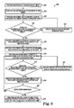
- FIG. 6 is a flow diagram illustrating a method of identifying a quadrilateral containing a specified point in a quadrilateral mesh according to one embodiment.
- FIG. 7 is a diagram illustrating a quadrilateral mesh containing a specified point according to one embodiment.
- FIG. 1A is a block diagram illustrating an image display system 100 according to one embodiment.
- Image display system 100 includes a processing system 101 , projectors 112 ( 1 ) through 112 (N) where N is greater than or equal to one (collectively referred to as projectors 112 ), and at least one camera 122 .
- Processing system 101 includes image frame buffer 104 , frame generator 108 , and calibration unit 124 .
- Processing system 101 receives streams of image frames 102 ( 1 ) through 102 (M) where M is greater than or equal to one (referred to collectively as image frames 102 ) using any suitable wired or wireless connections including any suitable network connection or connections.
- the streams of image frames 102 ( 1 ) through 102 (M) may be captured and transmitted by attached or remote image capture devices (not shown) such as cameras, provided by an attached or remote storage medium such as a hard-drive, a DVD or a CD-ROM, or otherwise accessed from one or more storage devices by processing system 101 .
- a first image capture device captures and transmits image frames 102 ( 1 )
- a second image capture device captures and transmits image frames 102 ( 2 )
- an Mth image capture device captures and transmits image frames 102 (M), etc.
- the image capture devices may be arranged in one or more remote locations and may transmit the streams of image frames 102 ( 1 ) through 102 (M) across one or more networks (not shown) using one or more network connections.
- Image frames 110 can be composed from image frames 102 in any manner.
- an image frame 110 can be formed by compositing part of a first image frame 102 and part of a second image frame 102 .
- Image frames 102 may be in any suitable video or still image format such as MPEG-2 (Moving Picture Experts Group), MPEG-4, JPEG (Joint Photographic Experts Group), JPEG 2000, TIFF (Tagged Image File Format), BMP (bit mapped format), RAW, PNG (Portable Network Graphics), GIF (Graphic Interchange Format), XPM (X Window System), SVG (Scalable Vector Graphics), and PPM (Portable Pixel Map).
- MPEG-2 Motion Picture Experts Group
- MPEG-4 Joint Photographic Experts Group
- JPEG 2000 Joint Photographic Experts Group
- TIFF Tagged Image File Format
- BMP bit mapped format
- RAW Raster Image File Format
- PNG Portable Network Graphics
- GIF Graphic Interchange Format
- XPM X Window System
- SVG Scalable Vector Graphics
- PPM Portable Pixel Map
- Image frame buffer 104 receives and buffers image frames 102 .
- Frame generator 108 processes buffered image frames 102 to form image frames 110 ( 1 ) through 110 (N) (collectively referred to as image frames 110 ).
- frame generator 108 processes a single stream of image frames 102 to form one or more image frames 110 .
- frame generator 108 processes multiple streams of image frames 102 to form one or more image frames 110 .
- frame generator 108 processes image frames 102 to define image frames 110 ( 1 ) through 110 (N) using respective geometric meshes 126 ( 1 ) through 126 (N) (collectively referred to as geometric meshes 126 ) and respective photometric correction information 128 ( 1 ) through 128 (N) (collectively referred to as photometric correction information 128 ).
- Frame generator 108 provides frames 110 ( 1 ) through 110 (N) to projectors 112 ( 1 ) through 112 (N), respectively.
- Projectors 112 ( 1 ) through 112 (N) store frames 110 ( 1 ) through 110 (N) in image frame buffers 113 ( 1 ) through 113 (N) (collectively referred to as image frame buffers 113 ), respectively.
- Projectors 112 ( 1 ) through 112 (N) project frames 110 ( 1 ) through 110 (N), respectively, onto display surface 116 to produce projected images 114 ( 1 ) through 114 (N) for viewing by one or more users.
- projectors 112 project frames 110 such that each displayed image 114 at least partially overlaps with another displayed image 114 .
- image display system 100 displays images 114 in at least partially overlapping positions (e.g., in a tiled format) on display surface 116 .
- Projected images 114 are defined to include any combination of pictorial, graphical, or textural characters, symbols, illustrations, or other representations of information. Projected images 114 may be still images, video images, or any combination of still and video images.
- Display surface 116 includes any suitable surface configured to display images 114 .
- display surface 116 forms a developable surface.
- the term developable surface is defined as a surface that is formed by folding, bending, cutting, and otherwise manipulating a planar sheet of material without stretching the sheet.
- a developable surface may be planar, piecewise planar, or non-planar.
- a developable surface may form a shape such as a cylindrical section or a parabolic section.
- Non-planar developable display surfaces may allow a viewer to feel immersed in the projected scene. In addition, such surfaces may fill most or all of a viewer's field of view which allows scenes to be viewed as if they are at the same scale as they would be seen in the real world.
- image display system 100 is configured to display projected images 114 onto a developable surface without geometric distortion.
- images 114 are projected to appear as if they have been “wallpapered” to the developable surface where no pixels of images 114 are stretched.
- the wallpaper-like appearance of images 114 on a developable surface appears to a viewer to be undistorted.
- FIG. 1B is a schematic diagram illustrating a planar surface 130 .
- planar surface 130 is a shape that can be created by moving a straight line segment ⁇ through 3D space.
- E 1 (t 1 ) and E 2 (t 2 ) represent endpoint curves 132 and 134 traced by the movement of the endpoints of the line segment ⁇ .
- Endpoint curves 132 and 134 swept out in 3D space by the endpoints of the line segment ⁇ are sufficient to define the entire surface 130 .
- endpoint curves 132 and 134 are straight, parallel lines.
- planar surface 130 When planar surface 130 is curved into a non-planar developable surface 140 without stretching as indicated by an arrow 136 , the straight endpoint curves 132 and 134 become curved endpoint curves 142 and 144 in the example of FIG. 1B .
- Curving planar surface 130 into non-planar surface 140 may be thought of as analogous to bending, folding, or wallpapering planar surface 130 onto a curved surface without stretching. Endpoint curves 142 and 144 swept out in 3D space by the endpoints of the line segment ⁇ are sufficient to define the entire surface 140 .
- Image display system 100 may be configured to construct a two-dimensional (2D) coordinate system corresponding to planar surface 130 from which non-planar surface 140 was created using a predetermined arrangement of identifiable points in fiducial marks on display surface 116 .
- the geometry of the predetermined arrangement of identifiable points may be described according to distance measurements between the identifiable points.
- the distances between a predetermined arrangement of points may all be scaled by a single scale factor without affecting the relative geometry of the points, and hence the scale of the distances between the points on display surface 116 does not need to be measured.
- the predetermined arrangement of points lie in fiducial marks along the curved endpoint curves E 1 (t 1 ) and E 2 (t 2 ) in display surface 116 .
- endpoint curves define a 2D coordinate system in the planar surface 130 created by flattening curved display surface 140 .
- E 1 (t 1 ) and E 2 (t 2 ) are parallel in surface 130 , with the connecting line segment ⁇ lying in the orthogonal direction at each t.
- image display system 100 displays images 114 on display surface 116 with a minimum amount of distortion, smooth brightness levels, and a smooth color gamut.
- frame generator 108 applies geometric and photometric correction to image frames 102 using geometric meshes 126 and photometric correction information 128 , respectively, in the process of rendering frames 110 .
- Geometric correction is described in additional detail in Section II below, and photometric correction is described in additional detail in U.S. patent application Ser. No. 11/455,306, filed on Jun. 16, 2006, and entitled MESH FOR RENDERING AN IMAGE FRAME, which is incorporated by reference
- Frame generator 108 may perform any suitable image decompression, color processing, and conversion on image frames 102 .
- frame generator 108 may convert image frames 102 from the YUV-4:2:0 format of an MPEG2 video stream to an RGB format.
- frame generator 108 may transform image frames 102 using a matrix multiply to translate, rotate, or scale image frames 102 prior to rendering.
- Frame generator 108 may perform any image decompression, color processing, color conversion, or image transforms prior to rendering image frames 102 with geometric meshes 126 and photometric correction information 128 .
- Calibration unit 124 generates geometric meshes 126 and photometric correction information 128 using images 123 captured by at least one camera 122 during a calibration process.
- Camera 122 may be any suitable image capture device configured to capture images 123 of display surface 116 .
- Camera 122 captures images 123 such that the images include screen fiducial marks 118 A and 118 B (shown as fiducial marker strips 118 A and 118 B in FIGS. 1C and 1D ) and projector fiducial marks 118 C on display surface 116 .
- Fiducial marks 118 A, 118 B, and 118 C are collectively referred to as fiducial marks 118 .
- Fiducial marks 118 may be any suitable pattern or set of patterns that include a set of points with predetermined arrangement of the points where the patterns are recognizable by a pattern recognition algorithm.
- Screen fiducial marks 118 A and 118 B may be permanently attached to display surface 116 or may be applied to display surface 116 only during the calibration process.
- Projector fiducial marks 118 C are projected onto display surface 116 by projectors 112 .
- projector fiducial marks 118 C cover the entire display area of display surface 116 , but only a subset of these fiducial marks 118 C are shown in FIGS. 1C and 1D to simplify the illustration.
- Calibration unit 124 uses the predetermined arrangement of points to create a mapping of display surface 116 .
- the predetermined arrangement of identifiable points may be described by distance measurements between the identifiable points in the 2D space of flattened display surface 116 , where the scale of the distance measurements is not necessarily known.
- Fiducial marks 118 A and 118 B may be located outside of the display area on display surface 116 where images 114 will appear when displayed by projectors 112 . In the embodiment shown in FIGS. 1C and 1D , fiducial marker strips 118 A and 118 B form black and white checkerboard patterns at the top and bottom of display surface 116 where the distance between the corners of the checkerboard patterns in the horizontal direction is known by image display system 100 .
- fiducial marks 118 A and 118 B may form any other suitable pattern.
- fiducial marks 118 A and 118 B may also consist of active light emitters, such as LEDs, lasers, or infrared light sources. These light sources may optionally be deactivated during display of images 114 on display surface 116 .
- camera 122 includes a single camera configured to capture images 123 that each includes the entirety of display surface 116 . In other embodiments, camera 122 includes multiple cameras each configured to capture images 123 that include a portion of display surface 116 where the combined images 123 of the multiple cameras include the entirety of display surface 116 .
- FIG. 1C is a schematic diagram illustrating the projection of partially overlapping images 114 ( 1 ) through 114 ( 6 ) onto a non-planar developable display surface 116 without correction.
- images 114 ( 1 ) through 114 ( 6 ) appear as a set of distorted (i.e., warped) and disjointed (i.e., unaligned) images.
- Each image 114 ( 1 ) through 114 ( 6 ) appears distorted because of the display of a planar image onto a non-planar surface, and the set of images 114 ( 1 ) through 114 ( 6 ) appears disjointed because images 114 are not spatially aligned or otherwise displayed in a uniform way on display surface 116 .
- regions of overlap between images 114 may appear brighter than non-overlapping regions.
- variations between projectors 112 may result in variations in brightness and color gamut between projected images 114 ( 1 ) through 114 ( 6 ).
- FIG. 1D is a schematic diagram illustrating the projection of images 114 ( 1 ) through 114 ( 6 ) onto non-planar developable display surface 116 with geometric and photometric correction.
- frame generator 108 unwarps, spatially aligns, and crops images 114 ( 1 ) through 114 ( 6 ) to minimize distortion in the display of images 114 ( 1 ) through 114 ( 6 ) on display surface 116 .
- Frame generator 108 spatially aligns images 114 ( 1 ) through 114 ( 6 ) as shown in FIG. 1D .
- frame generator 108 may smooth any variations in brightness and color gamut between projected images 114 ( 1 ) through 114 ( 6 ) by applying photometric correction.
- frame generator 108 may smooth variations in brightness in overlapping regions such as an overlapping region 150 between images 114 ( 1 ) and 114 ( 2 ), an overlapping region 152 between images 114 ( 2 ), 114 ( 3 ), and 114 ( 4 ), and an overlapping region 154 between images 114 ( 3 ), 114 ( 4 ), 114 ( 5 ), and 114 ( 6 ).
- Frame generator 108 may smooth variations in brightness between images 114 displayed with different projectors 112 .
- Processing system 101 includes hardware, software, firmware, or a combination of these.
- one or more components of processing system 101 are included in a computer, computer server, or other microprocessor-based system capable of performing a sequence of logic operations.
- processing can be distributed throughout the system with individual portions being implemented in separate system components, such as in a networked or multiple computing unit environment.
- Image frame buffer 104 includes memory for storing one or more image frames of the streams of image frames 102 .
- image frame buffer 104 constitutes a database of one or more image frames 102 .
- Image frame buffers 113 also include memory for storing image frames 110 .
- frame buffers 113 may be combined (e.g., into a single frame buffer) and may be external to projectors 112 (e.g., in processing system 101 or between processing system 101 and projectors 112 ) in other embodiments.
- Examples of image frame buffers 104 and 113 include non-volatile memory (e.g., a hard disk drive or other persistent storage device) and volatile memory (e.g., random access memory (RAM)).
- non-volatile memory e.g., a hard disk drive or other persistent storage device
- volatile memory e.g., random access memory (RAM)
- processing system 101 may be implemented in hardware, software, firmware, or any combination thereof.
- the implementation may be via one or more microprocessors, graphics processing units (GPUs), programmable logic devices, or state machines.
- functions of frame generator 108 and calibration unit 124 may be performed by separate processing systems in other embodiments.
- geometric meshes 126 and photometric correction information 128 may be provided from calibration unit 124 to frame generator 108 using any suitable wired or wireless connection or any suitable intermediate storage device.
- Components of the present invention may include computer-implemented methods and may reside in software on one or more computer-readable mediums.
- the term computer-readable medium as used herein is defined to include any kind of memory, volatile or non-volatile, such as floppy disks, hard disks, CD-ROMs, flash memory, read-only memory, and random access memory.
- image display system 100 applies geometric correction to image frames 102 as part of the process of rendering image frames 110 .
- the geometric correction according to one embodiment corrects geometric distortions caused by projection onto a non-planar surface 116 , and by noise introduced in finding fiducial points.
- image display system 100 displays images 114 on display surface 116 using image frames 110 such that viewers may view images as being undistorted for all viewpoints of display surface 116 .
- Image display system 100 generates geometric meshes 126 as part of a geometric calibration process. Image display system 100 determines geometric meshes 126 using predetermined arrangements of fiducial marks 118 . In one embodiment, image display system 100 determines geometric meshes 126 without knowing the shape or any dimensions of display surface 116 other than the predetermined arrangement of fiducial marks 118 .
- Frame generator 108 renders image frames 110 using respective geometric meshes 126 to unwarp, spatially align, and crop frames 102 into shapes that are suitable for display on display surface 116 .
- Frame generator 108 renders image frames 110 to create precise pixel alignment between overlapping images 114 in the overlap regions (e.g., regions 150 , 152 , and 154 in FIG. 1D ).
- the geometric calibration process uses fiducial points (e.g., fiducial marks 118 ), some of which are printed or physically placed, and some of which are projected, on the display surface 116 .
- calibration unit 124 generates calibration data for removing distortion that would otherwise be caused by noise that occurs when the fiducial points are located in the camera images 123 and projector frame buffers 113 or printed.
- homographic interpolation is used as part of the geometric calibration. Homographic interpolation can correctly model camera perspective projection geometry by eliminating the effect of camera position and viewing angle, and is suitable for wallpaper projection. The noise introduced in finding fiducial points can cause high frequency oscillations and interpolation ambiguity when using homographic interpolation.
- One embodiment uses a globally smooth function (e.g., parametric curve or surface) to regularize fiducial points, eliminate detection and measurement noise, and provide accurate homographic interpolation.
- a goal of the smoothing according to one embodiment is to regularize fiducial points so that the distances between points vary smoothly according to the correct geometry.
- a homography is a plane-to-plane transformation that can be uniquely determined by four pairs of corresponding fiducial points between two planes. Any points on the planes of the fiducials can be mapped from each other using the resulting homography or its inverse homography (i.e., homographic interpolation). As it correctly models the camera perspective projection geometry, homographic interpolation is suitable for computing the geometric mappings to achieve wallpaper projection.
- the display surface 116 is modeled as piecewise planar and can be approximated by a quadrilateral mesh, formed by connecting all adjacent fiducials 118 A and 118 B at the top and bottom of the surface 116 , and from every top ith fiducial to the corresponding bottom ith fiducial.
- a quadrilateral mesh formed by connecting all adjacent fiducials 118 A and 118 B at the top and bottom of the surface 116 , and from every top ith fiducial to the corresponding bottom ith fiducial.
- Each such quadrilateral on the display surface 116 and its corresponding quadrilateral in a camera image 123 can determine a unique homography, and any internal point within a quadrilateral can be computed by homographic interpolation.
- fiducial noise is removed, as described in further detail below.
- a projector domain coordinate system, P i represents coordinates in frame buffer 113 of the ith projector 112 .
- a camera domain coordinate system, C j represents coordinates in images 123 captured by the jth camera 122 .
- a screen domain coordinate system, S represents coordinates in the plane formed by flattening display surface 116 .
- an image frame domain coordinate system, I represent coordinates within image frames 102 to be rendered by frame generator 108 .
- Image display system 100 performs geometric correction on image frames 102 to conform images 114 to display surface 116 without distortion.
- the image frame domain coordinate system, I of image frames 102 may be considered equivalent to the screen domain coordinate system, S, up to a scale in each of the two dimensions.
- the image frame domain coordinate system, I becomes identical to the screen domain coordinate system, S. Therefore, if mappings between the screen domain coordinate system, S, and each projector domain coordinate system, P i , are determined, then the mappings between each projector domain coordinate system, P i , and the image frame domain coordinate system, I, may be determined.
- FIGS. 2A-2E are flow charts illustrating methods for geometric correction.
- FIG. 2A illustrates the overall calibration process to generate geometric meshes 126 according to one embodiment
- FIG. 2B illustrates the rendering process using geometric meshes 126 to perform geometric correction on image frames 102 according to one embodiment.
- FIGS. 2C through 2E illustrate additional details of the functions of the blocks shown in FIG. 2A .
- the embodiments of FIGS. 2A-2E will be described with reference to image display system 100 as illustrated in FIG. 1 .
- the methods of FIGS. 2A-2E will be described for an embodiment of image display system 100 that includes a single camera 122 .
- a quadrilateral mesh is formed by a set of quadrilaterals, where each quadrilateral is described with a set of four coordinate locations (e.g., corners of the quadrilateral).
- Each quadrilateral in a quadrilateral mesh corresponds to another quadrilateral (i.e., a set of four coordinate locations or corners) in another quadrilateral mesh from another domain.
- corresponding quadrilaterals in two domains may be represented by eight coordinate locations—four coordinate locations in the first domain and four coordinate locations in the second domain.
- calibration unit 124 generates a screen-to-camera mapping as indicated in a block 202 .
- calibration unit 124 computes homographies or inverse homographies that map between a quadrilateral mesh in the screen domain and a corresponding quadrilateral mesh in the camera domain.
- Calibration unit 124 generates this mapping using knowledge of a predetermined arrangement of fiducial marks 118 A and 118 B, and an image 123 captured by camera 122 that includes these fiducial marks 118 A and 118 B on display surface 116 .
- Calibration unit 124 also generates a camera-to-projector mapping for each projector 112 as indicated in a block 204 .
- calibration unit 124 computes homographies or inverse homographies that map between a second quadrilateral mesh in the camera domain and a corresponding quadrilateral mesh in the projector domain for each projector 112 .
- Calibration unit 124 generates these mappings from known pattern sequences, which contain projector fiducial marks 118 C, displayed by projectors 112 and a set of images 123 captured by camera 122 viewing display surface 116 while these known pattern sequences are projected by projectors 112 .
- Calibration unit 124 generates a screen-to-projector quadrilateral mesh, also referred to as geometric mesh 126 , for each projector 112 as indicated in a block 206 , using the screen-to-camera mapping generated at 202 and the camera-to-projector mappings generated at 204 .
- geometric meshes 126 will be described as quadrilateral meshes.
- geometric meshes 126 may be polygonal meshes formed by polygons with z sides, where z is greater than or equal to three.
- corresponding polygons in two domains may be represented by 2z ordered coordinate locations—z ordered coordinate locations in the first domain and z ordered coordinate locations in the second domain.
- frame generator 108 renders frames 110 for each projector 112 using the respective geometric mesh 126 as indicated in a block 208 .
- Frame generator 108 provides respective frames 110 to respective frame buffers 113 in respective projectors 112 .
- Projectors 112 project respective frames 110 onto display surface 116 in partially overlapping positions as indicated in a block 210 .
- each geometric mesh 126 defines a mapping between display surface 116 and a frame buffer 113 of a respective projector 112
- frame generator 108 uses geometric meshes 126 to warp frames 102 into frames 110 such that frames 110 appear spatially aligned and without distortion when projected by projectors 112 as images 114 in partially overlapping positions on display surface 116 .
- Frame generator 108 interpolates the pixel values for frames 110 from frames 102 using the geometric meshes 126 .
- FIG. 2C illustrates a method for performing the function of block 202 of FIG. 2A .
- the method of FIG. 2C illustrates one embodiment of generating a screen-to-camera mapping.
- the method of FIG. 2C will be described with reference to FIGS. 3A-3B .
- camera 122 captures an image 123 A (shown in FIG. 3A ) of display surface 116 that includes fiducial marks 118 A and 118 B as indicated in a block 212 .
- Fiducial marks 118 A and 118 B include points identifiable in image 123 A by calibration unit 124 where the arrangement of the points is predetermined.
- fiducial marks 118 A and 118 B may form a black and white checkerboard pattern where the distances between all adjacent corners are the same linear distance.
- Calibration unit 124 locates fiducial marks 118 A and 118 B in image 123 A as indicated in a block 214 .
- Calibration unit 124 locates fiducial marks 118 A and 118 B to identify where points are located according to a predetermined arrangement on display screen 116 .
- points 300 represent the fiducial marks 118 A and 118 B in a screen domain (S) 302 corresponding to display screen 116 .
- the fiducial marks 300 are separated by an example predetermined arrangement—with a predetermined separation distance (d 1 ) in the horizontal direction and a predetermined separation distance (d 2 ) in the vertical direction on display screen 116 .
- Points 310 represent the fiducial marks 118 A and 118 B in a camera domain (C) 312 that are identified in image 123 A by calibration unit 124 .
- fiducial marks 118 A and 118 B and correspondingly points 300 may be arranged with other known geometry, distances, and/or other scaling information between points.
- calibration unit 124 generates a set of point correspondences 308 between fiducial marks 118 A and 118 B detected in image 123 A (i.e., points 310 in camera domain 312 ) and fiducial marks 118 A and 118 B on display surface 116 (i.e., points 300 in screen domain 302 ) as indicated in a block 216 .
- the set of point correspondences 308 are represented by arrows that identify corresponding points in screen domain 302 and camera domain 312 .
- These correspondences are generated by matching detected fiducial marks in camera image 123 A (i.e., points 310 ) with the predetermined arrangement of fiducial marks 118 A and 118 B on display surface 116 .
- Calibration unit 124 performs a smoothing function on fiducial marks 118 A and 118 B detected in image 123 A (i.e., points 310 in camera domain 312 ) and fiducial marks 118 A and 118 B on display surface 116 (i.e., points 300 in screen domain 302 ), thereby generating a set of regularized fiducial marks having a smooth variation in spacing between adjacent fiducial marks, as indicated in a block 217 .
- such noise is removed at 217 by making use of the fact that the horizontal and vertical spacings between adjacent fiducial marks should vary smoothly both on the screen and in the camera image (constant interval is merely a special case of smooth varying), and a globally smooth function, such as a polynomial curve, parameterized by the sequential index of fiducials, is fitted to each of the top and bottom rows of both physical screen fiducials 118 A and 118 B (i.e., points 300 in screen domain 302 ) and detected camera image fiducials (i.e., points 310 in camera domain 312 ). The geometric coordinates of these fiducials are then adjusted according to the resulting smooth functions to ensure the smooth varying of the horizontal and vertical spacings.
- a globally smooth function such as a polynomial curve, parameterized by the sequential index of fiducials
- s is simply the sequential index number of the fiducials, providing a reference for regularizing (x, y).
- Equations IV and V can be rewritten as shown in the following Equations VI and VII, respectively:
- Equation VIII The least square fitting error is minimized as shown in the following Equation VIII:
- Calibration unit 124 determines a screen-to-camera mapping 452 using the set of correspondences 308 , and the regularized fiducial marks generated at 217 , as indicated in a block 218 .
- the screen-to-camera mapping 452 is used to map screen domain (S) 302 to camera domain (C) 312 and vice versa.
- Calibration unit 124 determines the screen-to-camera mapping using the method illustrated in FIG. 2D .
- FIG. 2D illustrates a method for generating a mapping between two domains.
- calibration unit 124 constructs a first quadrilateral mesh in a first domain and a second quadrilateral mesh in a second domain using regularized fiducial marks and a set of point correspondences between the regularized fiducial marks in the first domain and the second domain, as indicated in a block 222 .
- calibration unit 124 constructs a quadrilateral mesh 304 in screen domain 302 by connecting points 300 .
- Calibration unit 124 constructs a quadrilateral mesh 314 in camera domain 312 by connecting points 310 in the same way that corresponding points 300 , according to point correspondences 308 , are connected in screen domain 302 .
- Calibration unit 124 uses the set of point correspondences 308 to ensure that quadrilaterals in quadrilateral mesh 314 correspond to quadrilaterals in quadrilateral mesh 304 .
- points 300 A, 300 B, 300 C, and 300 D correspond to points 310 A, 310 B, 310 C, and 310 D as shown by the set of point correspondences 308 .
- calibration unit 124 formed a quadrilateral 304 A in quadrilateral mesh 304 using points 300 A, 300 B, 300 C, and 300 D
- calibration unit 124 also forms a quadrilateral 314 A in quadrilateral mesh 314 using points 310 A, 310 B, 310 C, and 310 D.
- Quadrilateral 314 A therefore corresponds to quadrilateral 304 A.
- calibration unit 124 computes a mapping 452 (e.g., homographies and inverse homographies) between the first quadrilateral mesh in the first domain and the second quadrilateral mesh in the second domain, as indicated in a block 224 .
- a homography is computed at 224 to map from each quadrilateral in the first domain, formed by regularized fiducials, to its corresponding regularized quadrilateral in the second domain.
- calibration unit 124 computes a homography to map from each quadrilateral in a quadrilateral mesh 304 in screen domain 302 to its corresponding quadrilateral in a quadrilateral mesh 314 in camera domain 312 .
- a homography is first computed at 224 to map from each quadrilateral in the second domain, formed by regularized fiducials, to its corresponding regularized quadrilateral in the first domain, and then the inverse of the resulting homography is computed to map from each quadrilateral in the first domain, formed by regularized fiducials, to its corresponding regularized quadrilateral in the second domain.
- calibration unit 124 may first compute a homography that maps each quadrilateral of a quadrilateral mesh 314 in camera domain 312 to its corresponding quadrilateral in a quadrilateral mesh 304 in screen domain 302 , and then compute the inverse of the resulting homography to map from each quadrilateral in a quadrilateral mesh 304 in screen domain 302 to its corresponding quadrilateral in a quadrilateral mesh 314 in camera domain 312 .
- FIG. 2E illustrates a method for performing the function of block 204 of FIG. 2A .
- the method of FIG. 2E illustrates one embodiment of generating camera-to-projector mappings.
- the method of FIG. 2E will be described with reference to FIGS. 4A-4B .
- the method of FIG. 2E is performed for each projector 112 to generate a camera-to-projector mapping for each projector 112 .
- calibration unit 124 causes a projector 112 to display a set of known pattern sequences, containing a plurality of projector fiducial marks 118 C, on display surface 116 , as indicated in a block 230 .
- calibration unit 124 provides a series of frames 110 with known patterns to frame buffer 113 in projector 112 by way of frame generator 108 .
- Projector 112 displays the series of known patterns.
- Camera 122 captures a set of images 123 B (shown in FIG. 4A ) of display surface 116 while the known patterns are being projected onto display surface 116 by projector 112 as indicated in a block 232 .
- the known patterns may be any suitable patterns that allow calibration unit 124 to identify projector fiducial marks 118 C in the patterns using images 123 B captured by camera 122 .
- the known patterns may be a sequence of horizontal and vertical black-and-white bar patterns, with the intersection points of the horizontal and vertical black-and-white bars being the projector fiducial marks 118 C.
- Calibration unit 124 locates fiducial marks of the known patterns in projector frame buffers 113 and fiducial marks of the known patterns in images 123 B as indicated in a block 234 .
- points 410 ( i ) represent the ith set of fiducial marks 118 C (where i is an integer between 1 and N) in an ith projector domain (P i ) 412 ( i ) corresponding to projector frame buffer 113 ( i ).
- Points 400 ( i ) represent the ith set of fiducial marks 118 C in camera domain (C) 312 that are identified in image 123 B(i) by calibration unit 124 .
- calibration unit 124 generates a set of point correspondences 408 ( i ) between an ith set of fiducial marks 118 C in the known patterns (in the coordinate space of the ith projector frame buffer 113 ( i ), i.e., points 410 ( i ) in projector domain 412 ( i )), and camera image 123 B(i) of these ith set of fiducial marks 118 C in the known patterns, i.e., points 400 ( i ) in camera domain 312 , as indicated in a block 236 .
- the ith set of point correspondences 408 ( i ) are represented by arrows that identify corresponding points in camera domain 312 and projector domain 412 ( i ).
- Calibration unit 124 performs a smoothing function on an ith set of fiducial marks 118 C in the known patterns in the ith projector frame buffer 113 ( i ), i.e., points 410 ( i ) in the projector domain 412 ( i ), and camera images 123 B(i) of these ith set of fiducial marks 118 C, i.e., points 400 ( i ) in camera domain 312 , thereby generating a set of regularized projector fiducial marks having a smooth variation in spacing between adjacent projector fiducial marks, as indicated in a block 237 .
- a globally smooth function such as a polynomial surface, parameterized by the horizontal and vertical indices of the regular grids, is fitted at 237 to the fiducial marks in the projector frame buffer 113 ( i ) and the camera image 123 B(i).
- the geometric coordinates of these detected fiducial marks are then adjusted according to the resulting smooth function to ensure the smooth varying of the horizontal and vertical spacings between adjacent fiducial marks.
- fiducial marks derived from the known projected patterns are regular grids of points 410 ( i ) with constant intervals in the horizontal and vertical directions. These points are projected onto the screen surface 116 and then observed by the camera 122 , yielding non-regular grids of points 400 ( i ) in the camera image 123 B(i).
- a parametric polynomial surface can be fitted to the non-regular grids in the camera image as shown in the following Equations IX and X:
- Equations IX and X can be obtained by minimizing the fitting error as shown in the following Equation XI:
- the two-dimensional coordinates of the camera image fiducials 400 ( i ) can be regularized according to Equations IX and X to cause the fiducials to vary smoothly.
- parametric curve fitting in Equations VI and VII is merely a degenerate case of the parametric surface fitting in Equations IX and X.
- Parametric surface fitting can be applied to the screen fiducial marks 118 A and 118 B, as well as the projector fiducial marks 118 C.
- parametric curve fitting may be better suited for regularizing the screen fiducials since, in some implementations, there may not be enough points to constrain the surface in the vertical direction.
- Calibration unit 124 determines a camera-to-projector mapping 456 ( i ) using the set of correspondences 408 ( i ) and the regularized projector fiducial marks generated at 237 , as indicated in a block 238 .
- the camera-to-projector mapping is used to map camera domain (C) 312 to projector domain (P i ) 412 ( i ) and vice versa.
- Calibration unit 124 determines the camera-to-projector mapping using the method illustrated in FIG. 2D .
- calibration unit 124 constructs a first quadrilateral mesh in a first domain and a second quadrilateral mesh in a second domain using regularized fiducial marks and a set of point correspondences between the regularized fiducial marks in the first and the second domain, as indicated in block 222 .
- calibration unit 124 constructs a quadrilateral mesh 404 ( i ) in camera domain 312 by connecting points 400 ( i ).
- Calibration unit 124 constructs a quadrilateral mesh 414 ( i ) in projector domain 412 ( i ) by connecting points 410 ( i ) in the same way that corresponding points 400 ( i ), according to point correspondences 408 ( i ), are connected in camera domain 312 .
- Calibration unit 124 uses the set of point correspondences 408 ( i ) to ensure that quadrilaterals in quadrilateral mesh 414 ( i ) correspond to quadrilaterals in quadrilateral mesh 404 ( i ).
- points 400 ( i )A, 400 ( i )B, 400 ( i )C, and 400 ( i )D correspond to points 410 ( i )A, 410 ( i )B, 410 ( i )C, and 410 ( i )D as shown by the set of point correspondences 408 ( i ).
- calibration unit 124 formed a quadrilateral 404 ( i )A in quadrilateral mesh 404 ( i ) using points 400 ( i )A, 400 ( i )B, 400 ( i )C, and 400 ( i )D
- calibration unit 124 also forms a quadrilateral 414 ( i )A in quadrilateral mesh 414 ( i ) using points 410 ( i )A, 410 ( i )B, 410 ( i )C, and 410 ( i )D.
- Quadrilateral 414 ( i )A therefore corresponds to quadrilateral 404 ( i )A.
- calibration unit 124 computes a mapping 456 ( i ) (e.g., homographies and inverse homographies) between the first quadrilateral mesh in the first domain and the second quadrilateral mesh in the second domain, as indicated in a block 224 .
- a homography is computed at 224 to map from each quadrilateral in the first domain, formed by regularized fiducials, to its corresponding regularized quadrilateral in the second domain.
- calibration unit 124 computes a homography to map from each quadrilateral in a quadrilateral mesh 404 ( i ) in camera domain 312 to its corresponding quadrilateral in a quadrilateral mesh 414 ( i ) in projector domain 412 ( i ).
- a homography is first computed at 224 to map from each quadrilateral in the second domain, formed by regularized fiducials, to its corresponding regularized quadrilateral in the first domain, and then the inverse of the resulting homography is computed to map from each quadrilateral in the first domain, formed by regularized fiducials, to its corresponding regularized quadrilateral in the second domain.
- calibration unit 124 may first compute a homography that maps each quadrilateral of quadrilateral mesh 414 ( i ) in projector domain 412 ( i ) to its corresponding quadrilateral mesh 404 ( i ) in camera domain 312 , and then compute the inverse of the resulting homography to map from each quadrilateral in a quadrilateral mesh 404 ( i ) in camera domain 312 to its corresponding quadrilateral in a quadrilateral mesh 414 ( i ) in projector domain 412 ( i ).
- calibration unit 124 generates a geometric mesh 126 from the screen 116 to each projector 112 using the screen-to-camera mapping (block 202 and FIG. 2C ) and camera-to-projector mapping for each projector 112 (block 204 and FIG. 2E ).
- Each geometric mesh 126 maps screen domain (S) 302 to a projector domain (P i ) 412 ( i ) and vice versa.
- frame generator 108 may warp frames 102 into frames 110 to geometrically correct the distortion caused by the projection of frames 110 from projector frame buffers 113 onto images 114 on the screen 116 .
- FIG. 2F illustrates a method for performing the function of block 206 of FIG. 2A .
- the method of FIG. 2F illustrates one embodiment of generating screen-to-projector quadrilateral meshes 126 .
- the method of FIG. 2F will be described with reference to FIGS. 5A-5B .
- the method of FIG. 2F is performed for each projector 112 to generate a screen-to-projector quadrilateral mesh 126 .
- Calibration unit 124 constructs a uniformly regular quadrilateral mesh to cover the display area in the screen domain, as indicated in a block 240 . Referring to FIG. 5A , calibration unit 124 constructs a uniformly regular quadrilateral mesh 454 in the screen domain 302 .
- calibration unit 124 generates a quadrilateral mesh in the camera image domain from the quadrilateral mesh in the screen domain using the screen-to-camera mapping, as indicated in a block 242 .
- calibration unit 124 generates a quadrilateral mesh 450 in the camera image domain 312 from the quadrilateral mesh 454 in the screen domain 302 using the screen-to-camera mapping 452 generated in a block 218 of FIG. 2C .
- calibration unit 124 generates a quadrilateral mesh in each projector domain from the quadrilateral mesh in the camera image domain using the corresponding camera-to-projector mapping, as indicated in a block 244 .
- calibration unit 124 generates a quadrilateral mesh 458 ( i ) in each projector domain 412 ( i ) from the quadrilateral mesh 450 in the camera image domain 312 using the corresponding camera-to-projector mapping 456 ( i ) generated in a block 238 of FIG. 2E .
- calibration unit 124 accesses the geometric correction data to determine corresponding points between two domains. For example, if calibration unit 124 is given a first point in the quadrilateral mesh for a first domain, frame generator 108 will first search for a quadrilateral in the quadrilateral mesh for the first domain that contains the point. Calibration unit 124 will then identify a second quadrilateral in the quadrilateral mesh for the second domain that corresponds to the first quadrilateral for the first domain, and determine the point within the second quadrilateral that corresponds to the first point.
- calibration unit 124 performs an iterative linear estimation quadrilateral search.
- calibration unit 124 performs separate row and column searches, performs a coarse estimation based on bounding boxes, iteratively adjusts the search range, and performs a strict geometric check only once or twice.
- FIG. 6 is a flow diagram illustrating a method 500 of identifying a quadrilateral containing a specified point in a quadrilateral mesh according to one embodiment.
- the method 500 shown in FIG. 6 will be described with further reference to FIG. 7 , which is a diagram illustrating a quadrilateral mesh 600 containing a specified point 612 (x, y) according to one embodiment.
- Quadrilateral mesh 600 is an irregular quadrilateral mesh with a plurality of quadrilaterals 604 and an irregular grid of points 602 that correspond to the corners of the quadrilaterals.
- the quadrilaterals 604 are organized into a plurality of columns 606 and a plurality of rows 608 .
- Also shown in FIG. 7 are a row bounding box 610 and a quadrilateral bounding box 614 , which are described in further detail below with reference to FIG. 6 and method 500 .
- an irregular quadrilateral mesh 600 is provided to calibration unit 124 .
- calibration unit 124 computes a row bounding box 610 for each row 608 in the mesh 600 .
- each bounding box 610 is larger than its corresponding row 608 of quadrilaterals 604 , and completely encompasses or provides a boundary around all of the quadrilaterals 604 in the row 608 corresponding to that bounding box 610 .
- calibration unit 124 performs an estimation to identify a row (e.g., row 608 A) in the mesh 600 that might contain the specified point 612 .
- a row 608 in a mesh is numbered incrementally from top to bottom. For example, the first row from the top of a mesh 600 is numbered 0, the second row from the top of a mesh 600 is numbered 1, and so on.
- calibration unit 124 performs the estimation at 506 using the following Equation XII:
- calibration unit 124 determines whether the bounding box 610 for the row 608 A identified at 506 contains the specified point 612 . If it is determined at 508 that the bounding box 610 for the row 608 A identified at 506 does not contain the specified point 612 , the method 500 moves to 510 . At 510 , calibration unit 124 reduces the search area in mesh 600 by removing rows 608 from the search area in mesh 600 .
- calibration unit 124 determines at 508 that the bounding box 610 for the row 608 A identified at 506 does not contain the specified point 612 , and that the specified point 612 is above the bounding box 610 , calibration unit 124 will discard the row 608 A from the identified rows, remove the rows 608 at and below the row 608 A identified at 506 from the search area, return to 506 , and repeat the search process using the reduced size search area, where bottom last and nRows have been updated according to the new search area.
- calibration unit 124 determines at 508 that the bounding box 610 for the row 608 A identified at 506 does not contain the specified point 612 , and that the specified point 612 is below the bounding box 610 , calibration unit 124 will discard the row 608 A from the set of identified rows, remove the rows 608 at and above the row 608 A identified at 506 from the search area, return to 506 , and repeat the search process using the reduced size search area, where top first and nRows have been updated according to the new search area.
- calibration unit 124 identifies rows 608 that neighbor the row 608 A identified at 506 and that have bounding boxes 610 that contain the specified point 612 , and adds these rows to the set of identified rows 608 A.
- calibration unit 124 computes a quadrilateral bounding box 614 for each quadrilateral 604 in that row 608 A.
- each quadrilateral bounding box 614 is larger than its corresponding quadrilateral 604 , and completely encompasses or provides a boundary around the quadrilateral 604 corresponding to that bounding box 614 .
- calibration unit 124 performs an estimation to identify a quadrilateral 604 A in an identified row 608 A that might contain the specified point 612 .
- a quadrilateral 604 in a row 608 A is numbered incrementally from left to right. For example, the first quadrilateral from the left of a row 608 A is numbered 0, the second quadrilateral from the left of a row 608 A is numbered 1, and so on.
- calibration unit 124 performs the estimation at 516 using the following Equation XIII:
- calibration unit 124 determines whether the bounding box 614 for the quadrilateral 604 A identified at 516 contains the specified point 612 . If it is determined at 518 that the bounding box 614 for the quadrilateral 604 A identified at 516 does not contain the specified point 612 , the method 500 moves to 520 . At 520 , calibration unit 124 reduces the search area in a row 608 A by removing quadrilaterals 604 from the search area in row 608 A.
- calibration unit 124 determines at 518 that the bounding box 614 for the quadrilateral 604 A identified at 516 does not contain the specified point 612 , and that the specified point 612 is to the left of the bounding box 614 , calibration unit 124 will discard the quadrilateral 604 A from the set of identified quadrilaterals, remove the quadrilaterals 604 at and to the right of the quadrilateral 604 A identified at 516 from the search area of row 608 A, return to 516 , and repeat the search process using the reduced size search area of row 608 A, where Right last and nQuads have been updated according to the new search area of row 608 A.
- calibration unit 124 determines at 518 that the bounding box 614 for the quadrilateral 604 A identified at 516 does not contain the specified point 612 , and that the specified point 612 is to the right of the bounding box 614 , calibration unit 124 will discard the quadrilateral 604 A from the set of identified quadrilaterals, remove the quadrilaterals 604 at and to the left of the quadrilateral 604 A identified at 516 from the search area of row 608 A, return to 516 , and repeat the search process using the reduced size search area of row 608 A, where left first and nQuads have been updated according to the new search area of row 608 A.
- calibration unit 124 determines whether there are any more of the rows 608 A identified at 506 and 512 remaining to be analyzed.
- calibration unit 124 goes through steps 516 - 522 for a first one of the identified rows 608 A, and then repeats these steps for each of the remaining identified rows 608 A. If it is determined at 524 that there are more rows 608 A remaining to be analyzed, the method 500 returns to 516 to analyze the next identified row 608 A.
- calibration unit 124 performs a geometric check on the quadrilaterals 604 A identified at 516 and 522 to identify a quadrilateral 604 that actually contains the specified point 612 .
- the geometric check performed at 526 is performed using vector geometry.
- the result of method 500 is to identify a quadrilateral 604 in mesh 600 that contains the specified point 612 .
- a next step in the process would be to identify a quadrilateral in a second quadrilateral mesh that corresponds to the quadrilateral identified by method 500 .
- a corresponding point within the identified quadrilateral in the second quadrilateral mesh would then be obtained by, for example, homographic interpolation.
- Method 500 according to one embodiment provides an efficient technique for quickly locating a quadrilateral in an irregular quadrilateral mesh. Locating a quadrilateral in a regular quadrilateral mesh is a simpler task, and a simplified version of method 500 can be used.
- calibration unit 124 is configured to generate at least one mesh based on images 123 of display surface 116 , and perform a smoothing function (e.g., parametric surface fitting) on fiducial marks appearing in the images 123 to generate regularized fiducial marks that have a smooth variation in spacing between adjacent fiducial marks.
- calibration unit 124 is configured to generate a geometric mapping based on the regularized fiducial marks, wherein the geometric mapping is configured to map a first domain associated with the display surface 116 to a second domain associated with a projector frame buffer 113 of a projector 112 .
- frame generator 108 is configured to generate an image frame for projection onto the display surface 116 by the projector 112 based on the geometric mapping.
- the above methods contemplate the use of an embodiment of display system 100 with multiple projectors 112 , the above methods may also be applied to an embodiment with a single projector 112 . In addition, the above methods may be used to perform geometric correction on non-developable display surfaces.
Landscapes
- Engineering & Computer Science (AREA)
- Multimedia (AREA)
- Signal Processing (AREA)
- Transforming Electric Information Into Light Information (AREA)
- Projection Apparatus (AREA)
Abstract
Description
μ[x′y′1]T =H[xy1]T Equation I
-
- Where:
- μ=scale factor;
- x, y=coordinates of a point in a first plane;
- x′, y′=coordinates of a point in a second plane;
- H=homographic transformation matrix; and
- T=transpose.
- Where:
v[xy1]T =H −1 [x′y′1]T Equation II
-
- Where:
- v=scale factor;
- x, y=coordinates of a point in a first plane;
- x′, y′=coordinates of a point in a second plane;
- H−1=inverse homographic transform matrix; and
- T=transpose.
- Where:
s′=h(s) Equation III
x=f x(s′)=f x(h(s)) Equation IV
y=f y(s′)=f y(h(s)) Equation V
Equations IX and X can be obtained by minimizing the fitting error as shown in the following Equation XI:
-
- Where:
- ({circumflex over (x)}uv, ŷuv)=measured coordinates.
- Where:
-
- Where:
- row=the number of the
row 608A inmesh 600 that is estimated to contain the specifiedpoint 612; - y=y-coordinate of the specified
point 612; - topfirst=y-position at the top of the
bounding box 610 for thefirst row 608 inmesh 600; - bottomlast=y-position at the bottom of the
bounding box 610 for thelast row 608 inmesh 600; and - nRows=the total number of
rows 608 inmesh 600.
- row=the number of the
- Where:
-
- Where:
- quad=the number of quadrilateral 604A in a
row 608A that is estimated to contain the specifiedpoint 612; - x=x-coordinate of the specified
point 612; - leftfirst=x-position at the left of the
first quadrilateral 604 in arow 608A; - rightlast=x-position at the right of the
last quadrilateral 604 in arow 608A; and - nQuads=the total number of
quadrilaterals 604 in arow 608A ofmesh 600.
- quad=the number of quadrilateral 604A in a
- Where:
Claims (19)
Priority Applications (1)
| Application Number | Priority Date | Filing Date | Title |
|---|---|---|---|
| US12/433,565 US8328365B2 (en) | 2009-04-30 | 2009-04-30 | Mesh for mapping domains based on regularized fiducial marks |
Applications Claiming Priority (1)
| Application Number | Priority Date | Filing Date | Title |
|---|---|---|---|
| US12/433,565 US8328365B2 (en) | 2009-04-30 | 2009-04-30 | Mesh for mapping domains based on regularized fiducial marks |
Publications (2)
| Publication Number | Publication Date |
|---|---|
| US20100277655A1 US20100277655A1 (en) | 2010-11-04 |
| US8328365B2 true US8328365B2 (en) | 2012-12-11 |
Family
ID=43030109
Family Applications (1)
| Application Number | Title | Priority Date | Filing Date |
|---|---|---|---|
| US12/433,565 Expired - Fee Related US8328365B2 (en) | 2009-04-30 | 2009-04-30 | Mesh for mapping domains based on regularized fiducial marks |
Country Status (1)
| Country | Link |
|---|---|
| US (1) | US8328365B2 (en) |
Cited By (8)
| Publication number | Priority date | Publication date | Assignee | Title |
|---|---|---|---|---|
| US20120098937A1 (en) * | 2009-04-28 | 2012-04-26 | Behzad Sajadi | Markerless Geometric Registration Of Multiple Projectors On Extruded Surfaces Using An Uncalibrated Camera |
| US20130169888A1 (en) * | 2011-12-22 | 2013-07-04 | Canon Kabushiki Kaisha | Method and device for controlling a video projector in a video projection system comprising multiple video projectors |
| US20130317352A1 (en) * | 2012-05-22 | 2013-11-28 | Vivant Medical, Inc. | Systems and Methods for Planning and Navigation |
| US20150029465A1 (en) * | 2013-07-26 | 2015-01-29 | Masaaki Ishikawa | Projection system, image processing device, and projection method |
| US20150049117A1 (en) * | 2012-02-16 | 2015-02-19 | Seiko Epson Corporation | Projector and method of controlling projector |
| US20150077573A1 (en) * | 2013-09-13 | 2015-03-19 | Masaaki Ishikawa | Projection system, image processing device, and projection method |
| US20150213584A1 (en) * | 2014-01-24 | 2015-07-30 | Ricoh Company, Ltd. | Projection system, image processing apparatus, and correction method |
| WO2019195884A1 (en) * | 2018-04-10 | 2019-10-17 | Immersaview Pty Ltd | Image calibration for projected images |
Families Citing this family (17)
| Publication number | Priority date | Publication date | Assignee | Title |
|---|---|---|---|---|
| US9465283B2 (en) * | 2009-11-06 | 2016-10-11 | Applied Minds, Llc | System for providing an enhanced immersive display environment |
| JP5440250B2 (en) * | 2010-02-26 | 2014-03-12 | セイコーエプソン株式会社 | Correction information calculation apparatus, image processing apparatus, image display system, and image correction method |
| JP5338718B2 (en) * | 2010-02-26 | 2013-11-13 | セイコーエプソン株式会社 | Correction information calculation apparatus, image processing apparatus, image display system, and image correction method |
| US8717389B2 (en) * | 2010-08-06 | 2014-05-06 | Canon Kabushiki Kaisha | Projector array for multiple images |
| US9439627B2 (en) * | 2012-05-22 | 2016-09-13 | Covidien Lp | Planning system and navigation system for an ablation procedure |
| US9439622B2 (en) * | 2012-05-22 | 2016-09-13 | Covidien Lp | Surgical navigation system |
| US9439623B2 (en) * | 2012-05-22 | 2016-09-13 | Covidien Lp | Surgical planning system and navigation system |
| US20160037144A1 (en) * | 2013-03-14 | 2016-02-04 | 3M Innovative Properties Company | Projection system comprising a non-rectangular projection screen, capable of projection alignment by using alignment marks and method of alignment therefor |
| KR20160034847A (en) * | 2013-03-15 | 2016-03-30 | 스케일러블 디스플레이 테크놀로지스, 인크. | System and method for calibrating a display system using a short throw camera |
| EP3146729B1 (en) * | 2014-05-21 | 2024-10-16 | Millennium Three Technologies Inc. | System comprising a helmet, a multi-camera array and an ad hoc arrangement of fiducial marker patterns and their automatic detection in images |
| CN106331668B (en) * | 2016-08-03 | 2019-03-19 | 深圳市Tcl高新技术开发有限公司 | A kind of image display method and its system projected more |
| US10009586B2 (en) * | 2016-11-11 | 2018-06-26 | Christie Digital Systems Usa, Inc. | System and method for projecting images on a marked surface |
| CN107105209B (en) * | 2017-05-22 | 2019-09-03 | 长春华懋科技有限公司 | Projected image geometric distortion automatic correction system and its bearing calibration |
| CN112566581B (en) | 2018-08-10 | 2024-03-19 | 柯惠有限合伙公司 | System for ablation visualization |
| CN111385546B (en) * | 2018-12-28 | 2022-07-19 | 中强光电股份有限公司 | Projection system and projection method |
| US11265387B2 (en) * | 2019-11-13 | 2022-03-01 | At&T Intellectual Property I, L.P. | Synchronizing multiple user devices in an immersive media environment using time-of-flight light patterns |
| US20230267642A1 (en) * | 2020-07-15 | 2023-08-24 | Purdue Research Foundation | Fiducial location |
Citations (126)
| Publication number | Priority date | Publication date | Assignee | Title |
|---|---|---|---|---|
| US4373784A (en) | 1979-04-27 | 1983-02-15 | Sharp Kabushiki Kaisha | Electrode structure on a matrix type liquid crystal panel |
| US4662746A (en) | 1985-10-30 | 1987-05-05 | Texas Instruments Incorporated | Spatial light modulator and method |
| US4811003A (en) | 1987-10-23 | 1989-03-07 | Rockwell International Corporation | Alternating parallelogram display elements |
| US4956619A (en) | 1988-02-19 | 1990-09-11 | Texas Instruments Incorporated | Spatial light modulator |
| US5061049A (en) | 1984-08-31 | 1991-10-29 | Texas Instruments Incorporated | Spatial light modulator and method |
| US5083857A (en) | 1990-06-29 | 1992-01-28 | Texas Instruments Incorporated | Multi-level deformable mirror device |
| US5146356A (en) | 1991-02-04 | 1992-09-08 | North American Philips Corporation | Active matrix electro-optic display device with close-packed arrangement of diamond-like shaped |
| US5309241A (en) | 1992-01-24 | 1994-05-03 | Loral Fairchild Corp. | System and method for using an anamorphic fiber optic taper to extend the application of solid-state image sensors |
| US5317409A (en) | 1991-12-03 | 1994-05-31 | North American Philips Corporation | Projection television with LCD panel adaptation to reduce moire fringes |
| US5319744A (en) | 1991-04-03 | 1994-06-07 | General Electric Company | Polygon fragmentation method of distortion correction in computer image generating systems |
| US5369739A (en) | 1993-07-09 | 1994-11-29 | Silicon Graphics, Inc. | Apparatus and method for generating point sample masks in a graphics display system |
| US5369450A (en) | 1993-06-01 | 1994-11-29 | The Walt Disney Company | Electronic and computational correction of chromatic aberration associated with an optical system used to view a color video display |
| US5386253A (en) | 1990-04-09 | 1995-01-31 | Rank Brimar Limited | Projection video display systems |
| US5402184A (en) | 1993-03-02 | 1995-03-28 | North American Philips Corporation | Projection system having image oscillation |
| US5409009A (en) | 1994-03-18 | 1995-04-25 | Medtronic, Inc. | Methods for measurement of arterial blood flow |
| US5490009A (en) | 1994-10-31 | 1996-02-06 | Texas Instruments Incorporated | Enhanced resolution for digital micro-mirror displays |
| US5557353A (en) | 1994-04-22 | 1996-09-17 | Stahl; Thomas D. | Pixel compensated electro-optical display system |
| US5689283A (en) | 1993-01-07 | 1997-11-18 | Sony Corporation | Display for mosaic pattern of pixel information with optical pixel shift for high resolution |
| US5751379A (en) | 1995-10-06 | 1998-05-12 | Texas Instruments Incorporated | Method to reduce perceptual contouring in display systems |
| US5842762A (en) | 1996-03-09 | 1998-12-01 | U.S. Philips Corporation | Interlaced image projection apparatus |
| US5889625A (en) | 1997-05-21 | 1999-03-30 | Raytheon Company | Chromatic aberration correction for display systems |
| US5897191A (en) | 1996-07-16 | 1999-04-27 | U.S. Philips Corporation | Color interlaced image projection apparatus |
| US5912773A (en) | 1997-03-21 | 1999-06-15 | Texas Instruments Incorporated | Apparatus for spatial light modulator registration and retention |
| US5920365A (en) | 1994-09-01 | 1999-07-06 | Touch Display Systems Ab | Display device |
| US5953148A (en) | 1996-09-30 | 1999-09-14 | Sharp Kabushiki Kaisha | Spatial light modulator and directional display |
| USH1812H (en) | 1997-10-24 | 1999-11-02 | Sun Microsystems, Inc. | Method for encoding bounding boxes of drawing primitives to be rendered for multi-resolution supersampled frame buffers |
| US5978518A (en) | 1997-02-25 | 1999-11-02 | Eastman Kodak Company | Image enhancement in digital image processing |
| US6017123A (en) | 1996-01-29 | 2000-01-25 | Hughes-Jvc Technology Corporation | Projected image blending for multiple images |
| US6025951A (en) | 1996-11-27 | 2000-02-15 | National Optics Institute | Light modulating microdevice and method |
| EP1001306A2 (en) | 1998-11-12 | 2000-05-17 | Olympus Optical Co., Ltd. | Image display apparatus |
| US6067143A (en) | 1998-06-04 | 2000-05-23 | Tomita; Akira | High contrast micro display with off-axis illumination |
| US6097854A (en) | 1997-08-01 | 2000-08-01 | Microsoft Corporation | Image mosaic construction system and apparatus with patch-based alignment, global block adjustment and pair-wise motion-based local warping |
| US6104375A (en) | 1997-11-07 | 2000-08-15 | Datascope Investment Corp. | Method and device for enhancing the resolution of color flat panel displays and cathode ray tube displays |
| US6115022A (en) | 1996-12-10 | 2000-09-05 | Metavision Corporation | Method and apparatus for adjusting multiple projected raster images |
| US6118584A (en) | 1995-07-05 | 2000-09-12 | U.S. Philips Corporation | Autostereoscopic display apparatus |
| US6141039A (en) | 1996-02-17 | 2000-10-31 | U.S. Philips Corporation | Line sequential scanner using even and odd pixel shift registers |
| US6184969B1 (en) | 1994-10-25 | 2001-02-06 | James L. Fergason | Optical display system and method, active and passive dithering using birefringence, color image superpositioning and display enhancement |
| US6219017B1 (en) | 1998-03-23 | 2001-04-17 | Olympus Optical Co., Ltd. | Image display control in synchronization with optical axis wobbling with video signal correction used to mitigate degradation in resolution due to response performance |
| US6222593B1 (en) | 1996-06-06 | 2001-04-24 | Olympus Optical Co. Ltd. | Image projecting system |
| US6239783B1 (en) | 1998-10-07 | 2001-05-29 | Microsoft Corporation | Weighted mapping of image data samples to pixel sub-components on a display device |
| US6243055B1 (en) | 1994-10-25 | 2001-06-05 | James L. Fergason | Optical display system and method with optical shifting of pixel position including conversion of pixel layout to form delta to stripe pattern by time base multiplexing |
| US6249289B1 (en) | 1996-11-27 | 2001-06-19 | Silicon Graphics, Inc. | Multi-purpose high resolution distortion correction |
| US6304677B1 (en) * | 1998-04-07 | 2001-10-16 | Adobe Systems Incorporated | Smoothing and fitting point sequences |
| US6313888B1 (en) | 1997-06-24 | 2001-11-06 | Olympus Optical Co., Ltd. | Image display device |
| US6317171B1 (en) | 1997-10-21 | 2001-11-13 | Texas Instruments Incorporated | Rear-screen projection television with spatial light modulator and positionable anamorphic lens |
| US6319744B1 (en) | 1999-06-03 | 2001-11-20 | Komatsu Ltd. | Method for manufacturing a thermoelectric semiconductor material or element and method for manufacturing a thermoelectric module |
| US20010055025A1 (en) | 1998-02-17 | 2001-12-27 | Sun Microsystems, Inc. | Graphics system configured to filter samples using a variable support filter |
| US20020024640A1 (en) | 2000-08-29 | 2002-02-28 | Olympus Optical Co., Ltd. | Image projection display apparatus using plural projectors and projected image compensation apparatus |
| US20020041364A1 (en) | 2000-10-05 | 2002-04-11 | Ken Ioka | Image projection and display device |
| US20020057278A1 (en) | 1999-08-06 | 2002-05-16 | Sony Corporation And Sony Pictures Entertainment, Inc. | Method and apparatus for the digital creation of fur effects |
| US6393145B2 (en) | 1999-01-12 | 2002-05-21 | Microsoft Corporation | Methods apparatus and data structures for enhancing the resolution of images to be rendered on patterned display devices |
| US6390050B2 (en) | 1999-04-01 | 2002-05-21 | Vaw Aluminium Ag | Light metal cylinder block, method of producing same and device for carrying out the method |
| US6456339B1 (en) | 1998-07-31 | 2002-09-24 | Massachusetts Institute Of Technology | Super-resolution display |
| US20030020809A1 (en) | 2000-03-15 | 2003-01-30 | Gibbon Michael A | Methods and apparatuses for superimposition of images |
| US6522356B1 (en) | 1996-08-14 | 2003-02-18 | Sharp Kabushiki Kaisha | Color solid-state imaging apparatus |
| US20030034974A1 (en) | 2001-08-15 | 2003-02-20 | Mitsubishi Electric Research Laboratories, Inc. | System and method for animating real objects with projected images |
| US20030038818A1 (en) | 2001-08-23 | 2003-02-27 | Tidwell Reed P. | System and method for auto-adjusting image filtering |
| US6536907B1 (en) | 2000-02-08 | 2003-03-25 | Hewlett-Packard Development Company, L.P. | Aberration compensation in image projection displays |
| US20030076325A1 (en) | 2001-10-18 | 2003-04-24 | Hewlett-Packard Company | Active pixel determination for line generation in regionalized rasterizer displays |
| US20030090597A1 (en) | 2000-06-16 | 2003-05-15 | Hiromi Katoh | Projection type image display device |
| US6657603B1 (en) | 1999-05-28 | 2003-12-02 | Lasergraphics, Inc. | Projector with circulating pixels driven by line-refresh-coordinated digital images |
| US6677956B2 (en) | 2001-08-15 | 2004-01-13 | Mitsubishi Electric Research Laboratories, Inc. | Method for cross-fading intensities of multiple images of a scene for seamless reconstruction |
| US20040017164A1 (en) | 2002-07-26 | 2004-01-29 | Belliveau Richard S. | Method and apparatus for controlling images with image projection lighting devices |
| US6695451B1 (en) | 1997-12-12 | 2004-02-24 | Hitachi, Ltd. | Multi-projection image display device |
| US6697522B1 (en) | 1999-09-29 | 2004-02-24 | Minolta Co., Ltd. | Image processing apparatus and method enabling proper correction of chromatic aberration |
| US6709116B1 (en) | 2003-03-21 | 2004-03-23 | Mitsubishi Electric Research Laboratories, Inc. | Shape-adaptive projector system |
| US20040076336A1 (en) | 2002-06-12 | 2004-04-22 | Bassi Zorawar S. | System and method for electronic correction of optical anomalies |
| US6729733B1 (en) | 2003-03-21 | 2004-05-04 | Mitsubishi Electric Research Laboratories, Inc. | Method for determining a largest inscribed rectangular image within a union of projected quadrilateral images |
| US20040085477A1 (en) | 2002-10-30 | 2004-05-06 | The University Of Chicago | Method to smooth photometric variations across multi-projector displays |
| US6733136B2 (en) | 2001-06-06 | 2004-05-11 | Spitz, Inc. | Video-based immersive theater |
| US20040109599A1 (en) * | 2002-12-10 | 2004-06-10 | Cho Seong Ik | Method for locating the center of a fiducial mark |
| US6755537B1 (en) | 2003-03-21 | 2004-06-29 | Mitsubishi Electric Research Laboratories, Inc. | Method for globally aligning multiple projected images |
| US20040169827A1 (en) | 2003-02-28 | 2004-09-02 | Mitsuo Kubo | Projection display apparatus |
| US6793350B1 (en) | 2003-03-21 | 2004-09-21 | Mitsubishi Electric Research Laboratories, Inc. | Projecting warped images onto curved surfaces |
| US20040184011A1 (en) | 2003-03-21 | 2004-09-23 | Ramesh Raskar | Self-configurable ad-hoc projector cluster |
| US20040218071A1 (en) | 2001-07-12 | 2004-11-04 | Benoit Chauville | Method and system for correcting the chromatic aberrations of a color image produced by means of an optical system |
| US6824271B2 (en) | 2002-05-31 | 2004-11-30 | Olympus Corporation | Multiprojection system and method of acquiring correction data in multiprojection system |
| US20040239885A1 (en) | 2003-04-19 | 2004-12-02 | University Of Kentucky Research Foundation | Super-resolution overlay in multi-projector displays |
| US20040239890A1 (en) | 2002-05-31 | 2004-12-02 | Microsoft Corporation | Curved-screen immersive rear projection display |
| US20040257540A1 (en) | 2003-04-16 | 2004-12-23 | Sebastien Roy | Single or multi-projector for arbitrary surfaces without calibration nor reconstruction |
| US6856420B1 (en) | 2000-07-31 | 2005-02-15 | Hewlett-Packard Development Company, L.P. | System and method for transferring data within a printer |
| US20050052623A1 (en) | 2003-05-23 | 2005-03-10 | Chao-Wang Hsiung | Projecting system |
| US6874420B2 (en) | 1999-10-22 | 2005-04-05 | Cc1, Inc. | System and method for register mark recognition |
| US20050078378A1 (en) | 2002-08-12 | 2005-04-14 | Geist Richard Edwin | Head-mounted virtual display apparatus for mobile activities |
| US20050089213A1 (en) * | 2003-10-23 | 2005-04-28 | Geng Z. J. | Method and apparatus for three-dimensional modeling via an image mosaic system |
| US20050117215A1 (en) | 2003-09-30 | 2005-06-02 | Lange Eric B. | Stereoscopic imaging |
| US6912293B1 (en) | 1998-06-26 | 2005-06-28 | Carl P. Korobkin | Photogrammetry engine for model construction |
| US6930681B2 (en) | 2001-08-14 | 2005-08-16 | Mitsubishi Electric Research Labs, Inc. | System and method for registering multiple images with three-dimensional objects |
| US20050213057A1 (en) | 2004-03-26 | 2005-09-29 | Canon Kabushiki Kaisha | Display optical system and image projector |
| US6952204B2 (en) | 2001-06-11 | 2005-10-04 | Canon Kabushiki Kaisha | 3D computer modelling apparatus |
| US6963348B2 (en) | 2002-05-31 | 2005-11-08 | Nvidia Corporation | Method and apparatus for display image adjustment |
| US20050271299A1 (en) | 2004-05-31 | 2005-12-08 | Olympus Corporation | Image transforming method, image transforming device and multiprojection system |
| US20060001543A1 (en) * | 2004-07-01 | 2006-01-05 | Ramesh Raskar | Interactive wireless tag location and identification system |
| US7006110B2 (en) | 2003-04-15 | 2006-02-28 | Nokia Corporation | Determining a coverage mask for a pixel |
| US7019713B2 (en) | 2002-10-30 | 2006-03-28 | The University Of Chicago | Methods and measurement engine for aligning multi-projector display systems |
| US7031512B2 (en) | 2002-04-18 | 2006-04-18 | Stmicroelectronics, Inc. | Method and system for 3D smoothing within the bound of error regions of matching curves |
| US7038712B1 (en) | 2002-04-18 | 2006-05-02 | Hewlett-Packard Development Company, L.P. | Geometric and photometric calibration of cameras |
| US7103203B2 (en) | 2001-10-30 | 2006-09-05 | Koninklijke Philips Electronics, N.V. | Medical imaging station with a function of extracting a path within a ramified object |
| US20060197915A1 (en) | 2005-03-04 | 2006-09-07 | Manabu Kobayashi | Reflection type projection display apparatus |
| US20060227301A1 (en) | 2005-04-08 | 2006-10-12 | Geert Matthys | Motorized blend alignment tool |
| US20060239549A1 (en) | 2005-04-26 | 2006-10-26 | Kelly Sean C | Method and apparatus for correcting a channel dependent color aberration in a digital image |
| US20060244930A1 (en) | 2005-04-28 | 2006-11-02 | Kohtaro Hayashi | Projection optical system |
| US7131733B2 (en) | 2003-03-26 | 2006-11-07 | Matsushita Electric Works, Ltd. | Method for creating brightness filter and virtual space creation system |
| US20060270932A1 (en) * | 2005-05-24 | 2006-11-30 | Shmuel Aharon | Simultaneous projection of multi-branched vessels and their context on a single image |
| US7156521B2 (en) | 2002-10-31 | 2007-01-02 | Seiko Epson Corporation | Projector for compensating chromatic aberration of magnification |
| US20070024620A1 (en) | 2005-08-01 | 2007-02-01 | Muller-Fischer Matthias H | Method of generating surface defined by boundary of three-dimensional point cloud |
| US20070035670A1 (en) | 2002-06-12 | 2007-02-15 | Silicon Optix Inc. | Ultra-thin image projection system |
| US20070097327A1 (en) | 2003-11-28 | 2007-05-03 | Masahiko Yatsu | Projection optical unit and projection image display apparatus |
| US7224526B2 (en) | 1999-12-08 | 2007-05-29 | Neurok Llc | Three-dimensional free space image projection employing Fresnel lenses |
| US7239360B2 (en) | 2002-06-12 | 2007-07-03 | Silicon Optix Inc. | Short throw projection system and method |
| US20070165192A1 (en) | 2006-01-13 | 2007-07-19 | Silicon Optix Inc. | Reduced field angle projection display system |
| US20070195277A1 (en) | 2004-02-20 | 2007-08-23 | Seiko Epson Corporation | Projector system for light modulation device |
| US20070195285A1 (en) | 2006-02-15 | 2007-08-23 | Mersive Technologies, Llc | Hybrid system for multi-projector geometry calibration |
| US20070253028A1 (en) | 2006-04-28 | 2007-11-01 | Simon Widdowson | Collage generation with occlusion costing |
| US20070279600A1 (en) | 2006-06-06 | 2007-12-06 | High End Systems | Method and apparatus for creating a collage from a plurality of stage lights |
| US7308157B2 (en) | 2003-02-03 | 2007-12-11 | Photon Dynamics, Inc. | Method and apparatus for optical inspection of a display |
| US20070291233A1 (en) * | 2006-06-16 | 2007-12-20 | Culbertson W Bruce | Mesh for rendering an image frame |
| US20070291184A1 (en) | 2006-06-16 | 2007-12-20 | Michael Harville | System and method for displaying images |
| US20070291189A1 (en) | 2006-06-16 | 2007-12-20 | Michael Harville | Blend maps for rendering an image frame |
| US20070291185A1 (en) | 2006-06-16 | 2007-12-20 | Gelb Daniel G | System and method for projecting multiple image streams |
| US20080024490A1 (en) | 2006-07-28 | 2008-01-31 | Microsoft Corporation | Real-time GPU rendering of piecewise algebraic surfaces |
| US7339625B2 (en) | 2004-06-28 | 2008-03-04 | Barco N.V. | Optical and electrical blending of display images |
| US20080123993A1 (en) | 2006-05-24 | 2008-05-29 | Simon Widdowson | Templated collage generation with occlusion costing |
| US20080221425A1 (en) * | 2007-03-09 | 2008-09-11 | Olson Eric S | System and method for local deformable registration of a catheter navigation system to image data or a model |
| US20090195758A1 (en) | 2008-01-31 | 2009-08-06 | Hewlett-Packard Development Company, L.P. | Meshes for separately mapping color bands |
| US7589729B2 (en) | 2002-05-15 | 2009-09-15 | Mental Images Gmbh | Image synthesis by rank-1 lattices |
-
2009
- 2009-04-30 US US12/433,565 patent/US8328365B2/en not_active Expired - Fee Related
Patent Citations (137)
| Publication number | Priority date | Publication date | Assignee | Title |
|---|---|---|---|---|
| US4373784A (en) | 1979-04-27 | 1983-02-15 | Sharp Kabushiki Kaisha | Electrode structure on a matrix type liquid crystal panel |
| US5061049A (en) | 1984-08-31 | 1991-10-29 | Texas Instruments Incorporated | Spatial light modulator and method |
| US4662746A (en) | 1985-10-30 | 1987-05-05 | Texas Instruments Incorporated | Spatial light modulator and method |
| US4811003A (en) | 1987-10-23 | 1989-03-07 | Rockwell International Corporation | Alternating parallelogram display elements |
| US4956619A (en) | 1988-02-19 | 1990-09-11 | Texas Instruments Incorporated | Spatial light modulator |
| US5386253A (en) | 1990-04-09 | 1995-01-31 | Rank Brimar Limited | Projection video display systems |
| US5083857A (en) | 1990-06-29 | 1992-01-28 | Texas Instruments Incorporated | Multi-level deformable mirror device |
| US5146356A (en) | 1991-02-04 | 1992-09-08 | North American Philips Corporation | Active matrix electro-optic display device with close-packed arrangement of diamond-like shaped |
| US5319744A (en) | 1991-04-03 | 1994-06-07 | General Electric Company | Polygon fragmentation method of distortion correction in computer image generating systems |
| US5317409A (en) | 1991-12-03 | 1994-05-31 | North American Philips Corporation | Projection television with LCD panel adaptation to reduce moire fringes |
| US5309241A (en) | 1992-01-24 | 1994-05-03 | Loral Fairchild Corp. | System and method for using an anamorphic fiber optic taper to extend the application of solid-state image sensors |
| US5689283A (en) | 1993-01-07 | 1997-11-18 | Sony Corporation | Display for mosaic pattern of pixel information with optical pixel shift for high resolution |
| US5402184A (en) | 1993-03-02 | 1995-03-28 | North American Philips Corporation | Projection system having image oscillation |
| US5369450A (en) | 1993-06-01 | 1994-11-29 | The Walt Disney Company | Electronic and computational correction of chromatic aberration associated with an optical system used to view a color video display |
| US5369739A (en) | 1993-07-09 | 1994-11-29 | Silicon Graphics, Inc. | Apparatus and method for generating point sample masks in a graphics display system |
| US5409009A (en) | 1994-03-18 | 1995-04-25 | Medtronic, Inc. | Methods for measurement of arterial blood flow |
| US5557353A (en) | 1994-04-22 | 1996-09-17 | Stahl; Thomas D. | Pixel compensated electro-optical display system |
| US5920365A (en) | 1994-09-01 | 1999-07-06 | Touch Display Systems Ab | Display device |
| US6243055B1 (en) | 1994-10-25 | 2001-06-05 | James L. Fergason | Optical display system and method with optical shifting of pixel position including conversion of pixel layout to form delta to stripe pattern by time base multiplexing |
| US6184969B1 (en) | 1994-10-25 | 2001-02-06 | James L. Fergason | Optical display system and method, active and passive dithering using birefringence, color image superpositioning and display enhancement |
| US5490009A (en) | 1994-10-31 | 1996-02-06 | Texas Instruments Incorporated | Enhanced resolution for digital micro-mirror displays |
| US6118584A (en) | 1995-07-05 | 2000-09-12 | U.S. Philips Corporation | Autostereoscopic display apparatus |
| US5751379A (en) | 1995-10-06 | 1998-05-12 | Texas Instruments Incorporated | Method to reduce perceptual contouring in display systems |
| US6017123A (en) | 1996-01-29 | 2000-01-25 | Hughes-Jvc Technology Corporation | Projected image blending for multiple images |
| US6141039A (en) | 1996-02-17 | 2000-10-31 | U.S. Philips Corporation | Line sequential scanner using even and odd pixel shift registers |
| US5842762A (en) | 1996-03-09 | 1998-12-01 | U.S. Philips Corporation | Interlaced image projection apparatus |
| US6222593B1 (en) | 1996-06-06 | 2001-04-24 | Olympus Optical Co. Ltd. | Image projecting system |
| US5897191A (en) | 1996-07-16 | 1999-04-27 | U.S. Philips Corporation | Color interlaced image projection apparatus |
| US6522356B1 (en) | 1996-08-14 | 2003-02-18 | Sharp Kabushiki Kaisha | Color solid-state imaging apparatus |
| US5953148A (en) | 1996-09-30 | 1999-09-14 | Sharp Kabushiki Kaisha | Spatial light modulator and directional display |
| US6249289B1 (en) | 1996-11-27 | 2001-06-19 | Silicon Graphics, Inc. | Multi-purpose high resolution distortion correction |
| US6025951A (en) | 1996-11-27 | 2000-02-15 | National Optics Institute | Light modulating microdevice and method |
| US6115022A (en) | 1996-12-10 | 2000-09-05 | Metavision Corporation | Method and apparatus for adjusting multiple projected raster images |
| US5978518A (en) | 1997-02-25 | 1999-11-02 | Eastman Kodak Company | Image enhancement in digital image processing |
| US5912773A (en) | 1997-03-21 | 1999-06-15 | Texas Instruments Incorporated | Apparatus for spatial light modulator registration and retention |
| US5889625A (en) | 1997-05-21 | 1999-03-30 | Raytheon Company | Chromatic aberration correction for display systems |
| US6313888B1 (en) | 1997-06-24 | 2001-11-06 | Olympus Optical Co., Ltd. | Image display device |
| US6097854A (en) | 1997-08-01 | 2000-08-01 | Microsoft Corporation | Image mosaic construction system and apparatus with patch-based alignment, global block adjustment and pair-wise motion-based local warping |
| US6317171B1 (en) | 1997-10-21 | 2001-11-13 | Texas Instruments Incorporated | Rear-screen projection television with spatial light modulator and positionable anamorphic lens |
| USH1812H (en) | 1997-10-24 | 1999-11-02 | Sun Microsystems, Inc. | Method for encoding bounding boxes of drawing primitives to be rendered for multi-resolution supersampled frame buffers |
| US6104375A (en) | 1997-11-07 | 2000-08-15 | Datascope Investment Corp. | Method and device for enhancing the resolution of color flat panel displays and cathode ray tube displays |
| US6695451B1 (en) | 1997-12-12 | 2004-02-24 | Hitachi, Ltd. | Multi-projection image display device |
| US20010055025A1 (en) | 1998-02-17 | 2001-12-27 | Sun Microsystems, Inc. | Graphics system configured to filter samples using a variable support filter |
| US6219017B1 (en) | 1998-03-23 | 2001-04-17 | Olympus Optical Co., Ltd. | Image display control in synchronization with optical axis wobbling with video signal correction used to mitigate degradation in resolution due to response performance |
| US6304677B1 (en) * | 1998-04-07 | 2001-10-16 | Adobe Systems Incorporated | Smoothing and fitting point sequences |
| US6067143A (en) | 1998-06-04 | 2000-05-23 | Tomita; Akira | High contrast micro display with off-axis illumination |
| US6912293B1 (en) | 1998-06-26 | 2005-06-28 | Carl P. Korobkin | Photogrammetry engine for model construction |
| US6456339B1 (en) | 1998-07-31 | 2002-09-24 | Massachusetts Institute Of Technology | Super-resolution display |
| US6239783B1 (en) | 1998-10-07 | 2001-05-29 | Microsoft Corporation | Weighted mapping of image data samples to pixel sub-components on a display device |
| EP1001306A2 (en) | 1998-11-12 | 2000-05-17 | Olympus Optical Co., Ltd. | Image display apparatus |
| US6384816B1 (en) | 1998-11-12 | 2002-05-07 | Olympus Optical, Co. Ltd. | Image display apparatus |
| US6393145B2 (en) | 1999-01-12 | 2002-05-21 | Microsoft Corporation | Methods apparatus and data structures for enhancing the resolution of images to be rendered on patterned display devices |
| US6390050B2 (en) | 1999-04-01 | 2002-05-21 | Vaw Aluminium Ag | Light metal cylinder block, method of producing same and device for carrying out the method |
| US6657603B1 (en) | 1999-05-28 | 2003-12-02 | Lasergraphics, Inc. | Projector with circulating pixels driven by line-refresh-coordinated digital images |
| US6319744B1 (en) | 1999-06-03 | 2001-11-20 | Komatsu Ltd. | Method for manufacturing a thermoelectric semiconductor material or element and method for manufacturing a thermoelectric module |
| US20020057278A1 (en) | 1999-08-06 | 2002-05-16 | Sony Corporation And Sony Pictures Entertainment, Inc. | Method and apparatus for the digital creation of fur effects |
| US6697522B1 (en) | 1999-09-29 | 2004-02-24 | Minolta Co., Ltd. | Image processing apparatus and method enabling proper correction of chromatic aberration |
| US6874420B2 (en) | 1999-10-22 | 2005-04-05 | Cc1, Inc. | System and method for register mark recognition |
| US7224526B2 (en) | 1999-12-08 | 2007-05-29 | Neurok Llc | Three-dimensional free space image projection employing Fresnel lenses |
| US6536907B1 (en) | 2000-02-08 | 2003-03-25 | Hewlett-Packard Development Company, L.P. | Aberration compensation in image projection displays |
| US20030020809A1 (en) | 2000-03-15 | 2003-01-30 | Gibbon Michael A | Methods and apparatuses for superimposition of images |
| US20030090597A1 (en) | 2000-06-16 | 2003-05-15 | Hiromi Katoh | Projection type image display device |
| US6856420B1 (en) | 2000-07-31 | 2005-02-15 | Hewlett-Packard Development Company, L.P. | System and method for transferring data within a printer |
| US6558006B2 (en) | 2000-08-29 | 2003-05-06 | Olympus Optical Co., Ltd. | Image projection display apparatus using plural projectors and projected image compensation apparatus |
| US20020024640A1 (en) | 2000-08-29 | 2002-02-28 | Olympus Optical Co., Ltd. | Image projection display apparatus using plural projectors and projected image compensation apparatus |
| US6814448B2 (en) | 2000-10-05 | 2004-11-09 | Olympus Corporation | Image projection and display device |
| US20020041364A1 (en) | 2000-10-05 | 2002-04-11 | Ken Ioka | Image projection and display device |
| US6733136B2 (en) | 2001-06-06 | 2004-05-11 | Spitz, Inc. | Video-based immersive theater |
| US6952204B2 (en) | 2001-06-11 | 2005-10-04 | Canon Kabushiki Kaisha | 3D computer modelling apparatus |
| US20040218071A1 (en) | 2001-07-12 | 2004-11-04 | Benoit Chauville | Method and system for correcting the chromatic aberrations of a color image produced by means of an optical system |
| US6930681B2 (en) | 2001-08-14 | 2005-08-16 | Mitsubishi Electric Research Labs, Inc. | System and method for registering multiple images with three-dimensional objects |
| US6677956B2 (en) | 2001-08-15 | 2004-01-13 | Mitsubishi Electric Research Laboratories, Inc. | Method for cross-fading intensities of multiple images of a scene for seamless reconstruction |
| US20030034974A1 (en) | 2001-08-15 | 2003-02-20 | Mitsubishi Electric Research Laboratories, Inc. | System and method for animating real objects with projected images |
| US20030038818A1 (en) | 2001-08-23 | 2003-02-27 | Tidwell Reed P. | System and method for auto-adjusting image filtering |
| US20030076325A1 (en) | 2001-10-18 | 2003-04-24 | Hewlett-Packard Company | Active pixel determination for line generation in regionalized rasterizer displays |
| US7103203B2 (en) | 2001-10-30 | 2006-09-05 | Koninklijke Philips Electronics, N.V. | Medical imaging station with a function of extracting a path within a ramified object |
| US7038712B1 (en) | 2002-04-18 | 2006-05-02 | Hewlett-Packard Development Company, L.P. | Geometric and photometric calibration of cameras |
| US7031512B2 (en) | 2002-04-18 | 2006-04-18 | Stmicroelectronics, Inc. | Method and system for 3D smoothing within the bound of error regions of matching curves |
| US7589729B2 (en) | 2002-05-15 | 2009-09-15 | Mental Images Gmbh | Image synthesis by rank-1 lattices |
| US6824271B2 (en) | 2002-05-31 | 2004-11-30 | Olympus Corporation | Multiprojection system and method of acquiring correction data in multiprojection system |
| US6963348B2 (en) | 2002-05-31 | 2005-11-08 | Nvidia Corporation | Method and apparatus for display image adjustment |
| US20040239890A1 (en) | 2002-05-31 | 2004-12-02 | Microsoft Corporation | Curved-screen immersive rear projection display |
| US20040076336A1 (en) | 2002-06-12 | 2004-04-22 | Bassi Zorawar S. | System and method for electronic correction of optical anomalies |
| US20070035670A1 (en) | 2002-06-12 | 2007-02-15 | Silicon Optix Inc. | Ultra-thin image projection system |
| US7239360B2 (en) | 2002-06-12 | 2007-07-03 | Silicon Optix Inc. | Short throw projection system and method |
| US20040017164A1 (en) | 2002-07-26 | 2004-01-29 | Belliveau Richard S. | Method and apparatus for controlling images with image projection lighting devices |
| US20050012474A1 (en) | 2002-07-26 | 2005-01-20 | Belliveau Richard S. | Method and apparatus for controlling images with image projection lighting devices |
| US20050078378A1 (en) | 2002-08-12 | 2005-04-14 | Geist Richard Edwin | Head-mounted virtual display apparatus for mobile activities |
| US7145726B2 (en) | 2002-08-12 | 2006-12-05 | Richard Geist | Head-mounted virtual display apparatus for mobile activities |
| US7019713B2 (en) | 2002-10-30 | 2006-03-28 | The University Of Chicago | Methods and measurement engine for aligning multi-projector display systems |
| US7038727B2 (en) | 2002-10-30 | 2006-05-02 | The University Of Chicago | Method to smooth photometric variations across multi-projector displays |
| US20040085477A1 (en) | 2002-10-30 | 2004-05-06 | The University Of Chicago | Method to smooth photometric variations across multi-projector displays |
| US7156521B2 (en) | 2002-10-31 | 2007-01-02 | Seiko Epson Corporation | Projector for compensating chromatic aberration of magnification |
| US20040109599A1 (en) * | 2002-12-10 | 2004-06-10 | Cho Seong Ik | Method for locating the center of a fiducial mark |
| US7308157B2 (en) | 2003-02-03 | 2007-12-11 | Photon Dynamics, Inc. | Method and apparatus for optical inspection of a display |
| US20040169827A1 (en) | 2003-02-28 | 2004-09-02 | Mitsuo Kubo | Projection display apparatus |
| US20040184013A1 (en) | 2003-03-21 | 2004-09-23 | Ramesh Raskar | Projecting warped images onto curved surfaces |
| US6755537B1 (en) | 2003-03-21 | 2004-06-29 | Mitsubishi Electric Research Laboratories, Inc. | Method for globally aligning multiple projected images |
| US20040184011A1 (en) | 2003-03-21 | 2004-09-23 | Ramesh Raskar | Self-configurable ad-hoc projector cluster |
| US6729733B1 (en) | 2003-03-21 | 2004-05-04 | Mitsubishi Electric Research Laboratories, Inc. | Method for determining a largest inscribed rectangular image within a union of projected quadrilateral images |
| US6834965B2 (en) | 2003-03-21 | 2004-12-28 | Mitsubishi Electric Research Laboratories, Inc. | Self-configurable ad-hoc projector cluster |
| US20040184010A1 (en) | 2003-03-21 | 2004-09-23 | Ramesh Raskar | Geometrically aware projector |
| US6709116B1 (en) | 2003-03-21 | 2004-03-23 | Mitsubishi Electric Research Laboratories, Inc. | Shape-adaptive projector system |
| US6793350B1 (en) | 2003-03-21 | 2004-09-21 | Mitsubishi Electric Research Laboratories, Inc. | Projecting warped images onto curved surfaces |
| US6811264B2 (en) | 2003-03-21 | 2004-11-02 | Mitsubishi Electric Research Laboratories, Inc. | Geometrically aware projector |
| US7131733B2 (en) | 2003-03-26 | 2006-11-07 | Matsushita Electric Works, Ltd. | Method for creating brightness filter and virtual space creation system |
| US7006110B2 (en) | 2003-04-15 | 2006-02-28 | Nokia Corporation | Determining a coverage mask for a pixel |
| US20040257540A1 (en) | 2003-04-16 | 2004-12-23 | Sebastien Roy | Single or multi-projector for arbitrary surfaces without calibration nor reconstruction |
| US20040239885A1 (en) | 2003-04-19 | 2004-12-02 | University Of Kentucky Research Foundation | Super-resolution overlay in multi-projector displays |
| US20050052623A1 (en) | 2003-05-23 | 2005-03-10 | Chao-Wang Hsiung | Projecting system |
| US20050117215A1 (en) | 2003-09-30 | 2005-06-02 | Lange Eric B. | Stereoscopic imaging |
| US20050089213A1 (en) * | 2003-10-23 | 2005-04-28 | Geng Z. J. | Method and apparatus for three-dimensional modeling via an image mosaic system |
| US20070097327A1 (en) | 2003-11-28 | 2007-05-03 | Masahiko Yatsu | Projection optical unit and projection image display apparatus |
| US20070195277A1 (en) | 2004-02-20 | 2007-08-23 | Seiko Epson Corporation | Projector system for light modulation device |
| US20050213057A1 (en) | 2004-03-26 | 2005-09-29 | Canon Kabushiki Kaisha | Display optical system and image projector |
| US20050271299A1 (en) | 2004-05-31 | 2005-12-08 | Olympus Corporation | Image transforming method, image transforming device and multiprojection system |
| US7339625B2 (en) | 2004-06-28 | 2008-03-04 | Barco N.V. | Optical and electrical blending of display images |
| US20060001543A1 (en) * | 2004-07-01 | 2006-01-05 | Ramesh Raskar | Interactive wireless tag location and identification system |
| US20060197915A1 (en) | 2005-03-04 | 2006-09-07 | Manabu Kobayashi | Reflection type projection display apparatus |
| US20060227301A1 (en) | 2005-04-08 | 2006-10-12 | Geert Matthys | Motorized blend alignment tool |
| US20060239549A1 (en) | 2005-04-26 | 2006-10-26 | Kelly Sean C | Method and apparatus for correcting a channel dependent color aberration in a digital image |
| US20060244930A1 (en) | 2005-04-28 | 2006-11-02 | Kohtaro Hayashi | Projection optical system |
| US20060270932A1 (en) * | 2005-05-24 | 2006-11-30 | Shmuel Aharon | Simultaneous projection of multi-branched vessels and their context on a single image |
| US20070024620A1 (en) | 2005-08-01 | 2007-02-01 | Muller-Fischer Matthias H | Method of generating surface defined by boundary of three-dimensional point cloud |
| US20070165192A1 (en) | 2006-01-13 | 2007-07-19 | Silicon Optix Inc. | Reduced field angle projection display system |
| US20070195285A1 (en) | 2006-02-15 | 2007-08-23 | Mersive Technologies, Llc | Hybrid system for multi-projector geometry calibration |
| US20070253028A1 (en) | 2006-04-28 | 2007-11-01 | Simon Widdowson | Collage generation with occlusion costing |
| US20080123993A1 (en) | 2006-05-24 | 2008-05-29 | Simon Widdowson | Templated collage generation with occlusion costing |
| US20070279600A1 (en) | 2006-06-06 | 2007-12-06 | High End Systems | Method and apparatus for creating a collage from a plurality of stage lights |
| US20070291233A1 (en) * | 2006-06-16 | 2007-12-20 | Culbertson W Bruce | Mesh for rendering an image frame |
| US20070291185A1 (en) | 2006-06-16 | 2007-12-20 | Gelb Daniel G | System and method for projecting multiple image streams |
| US20070291189A1 (en) | 2006-06-16 | 2007-12-20 | Michael Harville | Blend maps for rendering an image frame |
| US20070291184A1 (en) | 2006-06-16 | 2007-12-20 | Michael Harville | System and method for displaying images |
| US7854518B2 (en) | 2006-06-16 | 2010-12-21 | Hewlett-Packard Development Company, L.P. | Mesh for rendering an image frame |
| US20080024490A1 (en) | 2006-07-28 | 2008-01-31 | Microsoft Corporation | Real-time GPU rendering of piecewise algebraic surfaces |
| US20080221425A1 (en) * | 2007-03-09 | 2008-09-11 | Olson Eric S | System and method for local deformable registration of a catheter navigation system to image data or a model |
| US20090195758A1 (en) | 2008-01-31 | 2009-08-06 | Hewlett-Packard Development Company, L.P. | Meshes for separately mapping color bands |
Non-Patent Citations (27)
| Title |
|---|
| "Rough quadrilateralation from a triangular mesh via layer-based decomposition", IBM Technical Disclosure Bulletin, May 2000, UK, Issue 433, p. 907. * |
| A. Majumder et al., "Perceptual Photometric Seamlessness in Projection-Based Tiled Displays," In Acm Transactions on Graphics, vol. 24, No. 1, pp. 118-139; 2005. |
| A. Raij et al., "PixelFlex2: A Comprehensive, Automatic Casually-Aligned Multiprojector Display", IEEE Int'l Workshop on Projector-Camera Systems; Oct. 12, 2003. Nice, France. |
| A. Yasuda et al., "FLC Wobbling for High Resolution Projectors," Journal of teh SID; pp. 229-305, May 1997. |
| C. Jaynes et al., "Super-Resolution Composition in Multi-Projector Displays", IEEE Int'l Workshop on Projector Camera Systems; Oct. 2003; 8 pgs. |
| C.H. Brown Elliott et al., "Color Subpixel Rendering Projectors and Flat Panel Displays", SMPTE Advanced Motion Imaging Conference; pp. 1-4; Feb. 27-Mar. 1, 2003. |
| D. Tanguay et al., "Nizza: A Framework for Developing Real-Time Streaming Multimedia Applications", HP Laboratories, HPL-2004-132, Aug. 2, 2004; 9 pgs. |
| D.C. Chen, "Display Resolution Enhancement with Optical Scanners", Applied Optics, vol. 40, No. 5, pp. 636-643; Feb. 10, 2001. |
| D.H. Kelley, "Motion and Vision-II. Stabilized Spatio-Temporal Threashold Surface"; Journal of the Optical Society of America, vol. 69, No. 10; Oct. 1979. |
| Hewlett-Packard Development Company brochure entitled "The Use of Dual Graphics on the High-End HP xw9300 Workstation"; #5983-0684EN, 8 pgs.; Feb. 2005. |
| L.M. Chen et al., "Visual Resolution Limits for Color Matrix Displays-One Panel Projectors", vol. 13, pp. 221-226; 1992. |
| M. Ashdown et al.-"A Flexible Projector-Camera System for Multi-Planar Displays"-Proceedings of IEEE Conference on Computer Vision and Pattern Recognition-Jun. 27, 2004-vol. 2-pp. 165-172. |
| M. Brown et al.-"Camera-Base Calibration Techniques for Seamless Multi-projector Displays"-IEEE Transactions on Visualization and Computer Graphics-vol. 11 No. 2-Mar. 2005. |
| M. Brown et al., "A Practical and Flexible Tiled Display System"; In Pactific Conf. on Comp. Graphics and Apps., 2002. |
| M. Harville et al.-"Practical Methods for Geometric and Photometric Correction of Tiled Projector Displays on Curved Surfaces"-Conference on Computer Vision and Pattern Recognition, Jun. 17, 2006. |
| N. Chang, "Efficient Dense Correspondences Using Temporally-Encoded Light Patterns," IEEE Int'l Workshop on Projector-Camera Systems; Oct. 12, 2003. Nice, France. |
| Peterson, Samuel-"Computing Constrained Delaunay Triangulations" In The Plane, http://www.geom.uiuc.edu/%7Esamuelp/del-project.html: Jun. 16, 2003. |
| Plass, M., & Stone, M. (1983). Curve-fitting with piecewise parametric cubics. ACM SIGGRAPH Computer Graphics, 17(3), 229239. ACM Press. Retrieved from http://portal.acm.org/citation.cfm?doid=964967.801153. * |
| R. Raskar et al., "iLamps: Geometrically Aware and Self-Configuring Projectors", in ACM Transactions on Graphics; vol. 22, No. 3, 2003; pp. 809-818. |
| R. Raskar et al., "Multiprojector Displays Using Camera-Based Registration", In IEEE Visualization; pp. 61-168; 1999. |
| R. Raskar et al., "Seamless Projection Overlaps Using Image Warping and Intensity Blending", 4th Int'l Conf. on Virtual Systems and Multimedia; Gifu, Japan, Nov. 1998. |
| R. Surati, "Scalable Self-Calibrating Display Technology for Seamless Large-Scale Displays", PhD thesis, Dept. of Computer Science, MIT, 1998. |
| R. Szeliski, "Video Mosaics for Virtual Environments", IEEE Computer Graphics and Applications, pp. 22-30, Mar. 1996. |
| Silicon Optix webpage entitled "Geo-Features"; 1 pg., Downloaded: Jan. 31, 2008. |
| Silicon Optix webpage entitled "Geo-Overview"; 1 pg., Downloaded: Jan. 31, 2008. |
| Stone, Maureen C.-"Color and Brightness Appearance Issues for Tiled Displays"-Mar. 2001-Computer Graphics and Applications. |
| T. Tokita et al., "P-108: FLC Resolution-Enhancing Device for Projection Displays", pp. 638-641; SID 02 Digest 2002. |
Cited By (15)
| Publication number | Priority date | Publication date | Assignee | Title |
|---|---|---|---|---|
| US20120098937A1 (en) * | 2009-04-28 | 2012-04-26 | Behzad Sajadi | Markerless Geometric Registration Of Multiple Projectors On Extruded Surfaces Using An Uncalibrated Camera |
| US9195121B2 (en) * | 2009-04-28 | 2015-11-24 | The Regents Of The University Of California | Markerless geometric registration of multiple projectors on extruded surfaces using an uncalibrated camera |
| US9039194B2 (en) * | 2011-12-22 | 2015-05-26 | Canon Kabushiki Kaisha | Method and device for controlling a video projector in a video projection system comprising multiple video projectors |
| US20130169888A1 (en) * | 2011-12-22 | 2013-07-04 | Canon Kabushiki Kaisha | Method and device for controlling a video projector in a video projection system comprising multiple video projectors |
| US20150049117A1 (en) * | 2012-02-16 | 2015-02-19 | Seiko Epson Corporation | Projector and method of controlling projector |
| US9498182B2 (en) * | 2012-05-22 | 2016-11-22 | Covidien Lp | Systems and methods for planning and navigation |
| US20130317352A1 (en) * | 2012-05-22 | 2013-11-28 | Vivant Medical, Inc. | Systems and Methods for Planning and Navigation |
| US20150029465A1 (en) * | 2013-07-26 | 2015-01-29 | Masaaki Ishikawa | Projection system, image processing device, and projection method |
| US9532018B2 (en) * | 2013-07-26 | 2016-12-27 | Ricoh Company, Ltd. | Projection system, device and method for the output of calibration projection scenes |
| US20150077573A1 (en) * | 2013-09-13 | 2015-03-19 | Masaaki Ishikawa | Projection system, image processing device, and projection method |
| US9661257B2 (en) * | 2013-09-13 | 2017-05-23 | Ricoh Company, Ltd. | Projection system, image processing device, and projection method |
| US20150213584A1 (en) * | 2014-01-24 | 2015-07-30 | Ricoh Company, Ltd. | Projection system, image processing apparatus, and correction method |
| US9818377B2 (en) * | 2014-01-24 | 2017-11-14 | Ricoh Company, Ltd. | Projection system, image processing apparatus, and correction method |
| WO2019195884A1 (en) * | 2018-04-10 | 2019-10-17 | Immersaview Pty Ltd | Image calibration for projected images |
| US11375165B2 (en) | 2018-04-10 | 2022-06-28 | ImmersaView Pty., Ltd. | Image calibration for projected images |
Also Published As
| Publication number | Publication date |
|---|---|
| US20100277655A1 (en) | 2010-11-04 |
Similar Documents
| Publication | Publication Date | Title |
|---|---|---|
| US8328365B2 (en) | Mesh for mapping domains based on regularized fiducial marks | |
| US11592732B2 (en) | Camera-assisted arbitrary surface characterization and correction | |
| US9195121B2 (en) | Markerless geometric registration of multiple projectors on extruded surfaces using an uncalibrated camera | |
| US10540576B1 (en) | Panoramic camera systems | |
| US7854518B2 (en) | Mesh for rendering an image frame | |
| US7907792B2 (en) | Blend maps for rendering an image frame | |
| US8358873B2 (en) | Hybrid system for multi-projector geometry calibration | |
| US9137504B2 (en) | System and method for projecting multiple image streams | |
| KR102160839B1 (en) | Muti-projection system and method for projector calibration thereof | |
| Wei et al. | Fisheye video correction | |
| US10051250B2 (en) | Method of automatically correcting projection area based on image photographed by photographing device and system therefor | |
| JP4209938B2 (en) | Image processing apparatus and method, image processing program, and image processor | |
| US20070291047A1 (en) | System and method for generating scale maps | |
| US20070291184A1 (en) | System and method for displaying images | |
| US20040257540A1 (en) | Single or multi-projector for arbitrary surfaces without calibration nor reconstruction | |
| US20160028950A1 (en) | Panoramic Video from Unstructured Camera Arrays with Globally Consistent Parallax Removal | |
| US9398278B2 (en) | Graphical display system with adaptive keystone mechanism and method of operation thereof | |
| CN105308503A (en) | System and method for calibrating a display system using a short-range camera | |
| CN112734860A (en) | A pixel-by-pixel mapping projection geometry correction method based on arc-curtain prior information | |
| US20090195758A1 (en) | Meshes for separately mapping color bands | |
| CN116863101A (en) | Reconstruction model geometry and texture optimization method based on self-adaptive grid subdivision | |
| CN104902201B (en) | Based on moving view point with abnormity screen projection as real-time correction method | |
| Ibrahim et al. | Real-time seamless multi-projector displays on deformable surfaces | |
| JP4554231B2 (en) | Distortion parameter generation method, video generation method, distortion parameter generation apparatus, and video generation apparatus | |
| US20080101725A1 (en) | Image display system configured to update correspondences using arbitrary features |
Legal Events
| Date | Code | Title | Description |
|---|---|---|---|
| AS | Assignment |
Owner name: HEWLETT-PACKARD DEVELOPMENT COMPANY, L.P., TEXAS Free format text: ASSIGNMENT OF ASSIGNORS INTEREST;ASSIGNOR:WEI, SUN;REEL/FRAME:022623/0302 Effective date: 20090429 |
|
| ZAAA | Notice of allowance and fees due |
Free format text: ORIGINAL CODE: NOA |
|
| ZAAB | Notice of allowance mailed |
Free format text: ORIGINAL CODE: MN/=. |
|
| STCF | Information on status: patent grant |
Free format text: PATENTED CASE |
|
| FPAY | Fee payment |
Year of fee payment: 4 |
|
| MAFP | Maintenance fee payment |
Free format text: PAYMENT OF MAINTENANCE FEE, 8TH YEAR, LARGE ENTITY (ORIGINAL EVENT CODE: M1552); ENTITY STATUS OF PATENT OWNER: LARGE ENTITY Year of fee payment: 8 |
|
| FEPP | Fee payment procedure |
Free format text: MAINTENANCE FEE REMINDER MAILED (ORIGINAL EVENT CODE: REM.); ENTITY STATUS OF PATENT OWNER: LARGE ENTITY |
|
| LAPS | Lapse for failure to pay maintenance fees |
Free format text: PATENT EXPIRED FOR FAILURE TO PAY MAINTENANCE FEES (ORIGINAL EVENT CODE: EXP.); ENTITY STATUS OF PATENT OWNER: LARGE ENTITY |
|
| STCH | Information on status: patent discontinuation |
Free format text: PATENT EXPIRED DUE TO NONPAYMENT OF MAINTENANCE FEES UNDER 37 CFR 1.362 |
|
| FP | Lapsed due to failure to pay maintenance fee |
Effective date: 20241211 |