US8322694B2 - Vibration isolator - Google Patents
Vibration isolator Download PDFInfo
- Publication number
- US8322694B2 US8322694B2 US12/311,515 US31151507A US8322694B2 US 8322694 B2 US8322694 B2 US 8322694B2 US 31151507 A US31151507 A US 31151507A US 8322694 B2 US8322694 B2 US 8322694B2
- Authority
- US
- United States
- Prior art keywords
- bellows
- flange
- vibration isolator
- resilient element
- isolator according
- Prior art date
- Legal status (The legal status is an assumption and is not a legal conclusion. Google has not performed a legal analysis and makes no representation as to the accuracy of the status listed.)
- Expired - Fee Related, expires
Links
Images


Classifications
-
- F—MECHANICAL ENGINEERING; LIGHTING; HEATING; WEAPONS; BLASTING
- F04—POSITIVE - DISPLACEMENT MACHINES FOR LIQUIDS; PUMPS FOR LIQUIDS OR ELASTIC FLUIDS
- F04D—NON-POSITIVE-DISPLACEMENT PUMPS
- F04D29/00—Details, component parts, or accessories
- F04D29/66—Combating cavitation, whirls, noise, vibration or the like; Balancing
- F04D29/661—Combating cavitation, whirls, noise, vibration or the like; Balancing especially adapted for elastic fluid pumps
- F04D29/668—Combating cavitation, whirls, noise, vibration or the like; Balancing especially adapted for elastic fluid pumps damping or preventing mechanical vibrations
-
- F—MECHANICAL ENGINEERING; LIGHTING; HEATING; WEAPONS; BLASTING
- F04—POSITIVE - DISPLACEMENT MACHINES FOR LIQUIDS; PUMPS FOR LIQUIDS OR ELASTIC FLUIDS
- F04B—POSITIVE-DISPLACEMENT MACHINES FOR LIQUIDS; PUMPS
- F04B37/00—Pumps having pertinent characteristics not provided for in, or of interest apart from, groups F04B25/00 - F04B35/00
- F04B37/10—Pumps having pertinent characteristics not provided for in, or of interest apart from, groups F04B25/00 - F04B35/00 for special use
- F04B37/14—Pumps having pertinent characteristics not provided for in, or of interest apart from, groups F04B25/00 - F04B35/00 for special use to obtain high vacuum
-
- F—MECHANICAL ENGINEERING; LIGHTING; HEATING; WEAPONS; BLASTING
- F04—POSITIVE - DISPLACEMENT MACHINES FOR LIQUIDS; PUMPS FOR LIQUIDS OR ELASTIC FLUIDS
- F04B—POSITIVE-DISPLACEMENT MACHINES FOR LIQUIDS; PUMPS
- F04B39/00—Component parts, details, or accessories, of pumps or pumping systems specially adapted for elastic fluids, not otherwise provided for in, or of interest apart from, groups F04B25/00 - F04B37/00
- F04B39/0027—Pulsation and noise damping means
- F04B39/0044—Pulsation and noise damping means with vibration damping supports
-
- F—MECHANICAL ENGINEERING; LIGHTING; HEATING; WEAPONS; BLASTING
- F04—POSITIVE - DISPLACEMENT MACHINES FOR LIQUIDS; PUMPS FOR LIQUIDS OR ELASTIC FLUIDS
- F04D—NON-POSITIVE-DISPLACEMENT PUMPS
- F04D17/00—Radial-flow pumps, e.g. centrifugal pumps; Helico-centrifugal pumps
- F04D17/08—Centrifugal pumps
- F04D17/16—Centrifugal pumps for displacing without appreciable compression
- F04D17/168—Pumps specially adapted to produce a vacuum
-
- F—MECHANICAL ENGINEERING; LIGHTING; HEATING; WEAPONS; BLASTING
- F04—POSITIVE - DISPLACEMENT MACHINES FOR LIQUIDS; PUMPS FOR LIQUIDS OR ELASTIC FLUIDS
- F04D—NON-POSITIVE-DISPLACEMENT PUMPS
- F04D19/00—Axial-flow pumps
- F04D19/02—Multi-stage pumps
- F04D19/04—Multi-stage pumps specially adapted to the production of a high vacuum, e.g. molecular pumps
-
- F—MECHANICAL ENGINEERING; LIGHTING; HEATING; WEAPONS; BLASTING
- F16—ENGINEERING ELEMENTS AND UNITS; GENERAL MEASURES FOR PRODUCING AND MAINTAINING EFFECTIVE FUNCTIONING OF MACHINES OR INSTALLATIONS; THERMAL INSULATION IN GENERAL
- F16F—SPRINGS; SHOCK-ABSORBERS; MEANS FOR DAMPING VIBRATION
- F16F15/00—Suppression of vibrations in systems; Means or arrangements for avoiding or reducing out-of-balance forces, e.g. due to motion
- F16F15/02—Suppression of vibrations of non-rotating, e.g. reciprocating systems; Suppression of vibrations of rotating systems by use of members not moving with the rotating systems
- F16F15/04—Suppression of vibrations of non-rotating, e.g. reciprocating systems; Suppression of vibrations of rotating systems by use of members not moving with the rotating systems using elastic means
- F16F15/06—Suppression of vibrations of non-rotating, e.g. reciprocating systems; Suppression of vibrations of rotating systems by use of members not moving with the rotating systems using elastic means with metal springs
- F16F15/067—Suppression of vibrations of non-rotating, e.g. reciprocating systems; Suppression of vibrations of rotating systems by use of members not moving with the rotating systems using elastic means with metal springs using only wound springs
Definitions
- This invention relates to a vibration isolator for inhibiting transfer of vibration to an apparatus during evacuation thereof by a pump.
- Vibration isolators are used to reduce the vibration transmitted to an apparatus from a high-vacuum pump, for example, a turbomolecular pump, during evacuation of the apparatus.
- the use of a vibration isolator is particularly desirable when the apparatus under evacuation is sensitive to mechanical vibration.
- the transmission of vibrations to an electron microscope can lead to a loss of resolution of the microscope, while the transmission of vibrations to a process tool can lead to manufacturing errors in products located within the tool.
- the present invention provides a vibration isolator for inhibiting transfer of vibration to an apparatus during evacuation thereof by a pump, the isolator comprising a bellows for conveying fluid drawn from the apparatus to the pump, the bellows having first and second open ends, and a resilient element substantially co-axial with and surrounded by the bellows, the resilient element having a first end connected to one of the first and second open ends, and a second end connected to the other one of the first and second open ends.
- FIG. 1 illustrates an isolator connected between a pump and an apparatus to be evacuated by the pump
- FIG. 2 is a cross-section through a known vibration isolator
- FIG. 3 is a top view of an example of a vibration isolator according to the present invention.
- FIGS. 4A-4C illustrate various cross-sectional views of the isolator of FIG. 3 , as viewed along line A-A, in accordance with various embodiments of the invention
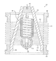
- FIG. 5 is a cross-sectional view of the isolator of FIG. 3 , as viewed along line B-B;
- FIG. 6 is an isometric rear view of the isolator of FIG. 3 .
- a vibration isolator 10 is typically connected between the fluid exhaust of the apparatus 12 to be evacuated and the fluid inlet of the vacuum pump 14 .
- FIG. 2 illustrates in more detail one example of a known vibration isolator 10 .
- the isolator 10 comprises a steel bellows 20 that defines a flow path through the isolator 10 for fluid pumped from the apparatus 12 by the pump 14 .
- a first annular flange 22 is welded to one end of the bellows 20 for connecting the isolator 10 to the apparatus 12 to be evacuated, and a second annular flange 24 is welded to the other end of the bellows 20 for connecting the isolator 10 to the pump 14 .
- the bellows 20 is surrounded by an elastomeric cylinder 26 mounted on the second flange 24 that prevents the bellows 20 from collapsing under compression when the fluid within the bellows is at a sub-atmospheric pressure, and provides damping of vibrations generated during use of the pump 14 .
- the isolator 10 further comprises a pair of interlinking members that prevent the bellows 20 from extending under the weight of a pump 14 connected to the second flange 24 when the apparatus is not under evacuation.
- Each interlinking member is in the form of a V-shaped metallic strap, with the first strap 28 being welded to the first flange 22 , and the second strap 30 being welded to the second flange 24 so that the straps 28 , 30 are linked.
- the straps 28 , 30 are spaced apart by a distance x extending along the axis of the bellows 20 .
- the parameter governing transmission of vibration from the pump 14 to the apparatus 12 is the stiffness of the isolator 10 .
- the bellows 20 typically has a relatively low inherent axial stiffness, there is minimal transmission of vibration to the apparatus 12 through the bellows 20 .
- the isolator 10 is under compression, and so the straps 28 , 30 are not in contact. Consequently, the primary route for the transmission of vibrations to the apparatus 12 is through the elastomeric cylinder 26 , which becomes sandwiched between the flanges 22 , 24 during evacuation of the apparatus.
- the elastomeric cylinder 26 when the elastomeric cylinder 26 is compressed in this manner, its hyperelasticity, reflected in a non-linear progressive stiffness characteristic, causes its axial stiffness to gradually increase.
- the increasing axial stiffness of the cylinder 26 reduces the ability of the isolator 10 to deflect, which progressively enhances the transmission of vibration to the apparatus 12 .
- the present invention provides a vibration isolator for inhibiting transfer of vibration to an apparatus during evacuation thereof by a pump, the isolator comprising a bellows for conveying fluid drawn from the apparatus to the pump, the bellows having first and second open ends, and a resilient element substantially co-axial with and surrounded by the bellows, the resilient element having a first end connected to one of the first and second open ends, and a second end connected to the other one of the first and second open ends.
- the invention can thus provide a vibration isolator having a relatively simple structure and with relatively low axial, shear and tilt stiffnesses.
- the bellow may be integral with the pump, with the second open end of the bellows being connected to the body of the pump.
- this open end of the bellows may be connected to an annular flange integral with the housing of the pump.
- a separate flange may be connected to this second open end of the bellows for mounting the isolator to a pump, with one end of the resilient element being connected to the second flange.
- another flange is preferably connected to the first open end of the bellows for mounting the isolator to an apparatus to be evacuated, with the other end of the resilient element being connected to the first flange.
- the first end of the resilient element is located proximate to the first open end of the bellows and connected to the second open end of the bellows, and the second end of the resilient element is located proximate to the second open end of the bellows and connected to the first open end of the bellows.
- the isolator may be in the form of a component which is mounted to both the apparatus and the pump, and so in a second aspect the present invention provides a vibration isolator for inhibiting transfer of vibration to an apparatus during evacuation thereof by a pump, the isolator comprising a bellows for conveying fluid drawn from the apparatus to the pump, a first flange connected to one end of the bellows for mounting the isolator to the apparatus, a second flange connected to the other end of the bellows for mounting the isolator to the pump, and a resilient element co-axial with and surrounded by the bellows, the resilient element having a first end located proximate to the first flange and connected to the second flange, and a second end located proximate to the second flange and connected to the first flange.
- the vibration isolator preferably comprises a first connector connected to the first flange, and a second connector connected to the second flange, with the first end of the resilient member being attached to the second connector, and the second end of the resilient member being attached to the first connector.
- These connectors are preferably overlapping, and thus are preferably angularly offset.
- the first connector is substantially orthogonal to the second connector.
- Each connector may be provided by an arch-shaped connector having ends connected to its respective flange and a central portion attached to the resilient element.
- the isolator may comprise damping means for damping oscillation or vibration of the resilient element.
- the damping means may preferably comprise a plastics element which contacts at least a portion of the resilient element during use.
- Damping means may be located between each end of the resilient member and its respective connector.
- an elastomeric sleeve may surround the bellows.
- the isolator may comprise an auxiliary mass which can be located to increase a resistance to axial compression of said bellows when a fluid within said bellows is at a sub-atmospheric pressure.
- the second flange comprises connection means for connecting said auxiliary mass thereto.
- the resilient element is preferably under tension, and thus may be provided by a helical tension spring.
- the tension spring is preferably pre-tensioned.
- FIG. 3 illustrates a vibration isolator 50 for connection between the fluid exhaust of an apparatus to be evacuated, and the fluid inlet of a vacuum pump.
- the isolator 50 comprises a steel bellows 60 of generally cylindrical form having a first open end 62 and a second open end 64 .
- the bellows 60 defines a flow path through the isolator 50 for fluid pumped from the apparatus by the pump.
- a first annular flange 66 is welded to the first open end 62 of the bellows 60 for connecting the isolator 50 to the apparatus to be evacuated, and a second annular flange 68 is welded to the second open end 64 of the bellows 60 for connecting the isolator 50 to the pump.
- the bellows 60 surrounds a resilient element 70 , which is preferably under tension in the normal, unloaded condition and therefore is preferably in the form of a helical tension spring.
- the tension spring is preferably a pre-tensioned spring.
- the resilient element 70 is substantially co-axial with the bellows 60 .
- the resilient element 70 has a first end 72 located proximate to the first flange 66 , and a second end 74 located proximate to the second flange 68 .
- a first connector 76 is provided for connecting the resilient element 70 to the first open end 62 of the bellows 60
- a second connector 78 is provided for connecting the resilient element 70 to the second open end 64 of the bellows 60 .
- the first connector 76 is in the form of an arch-shaped connector, having a central portion 80 attached to the second end 74 of the resilient element 70 and ends 82 welded or otherwise connected to the first flange 66 .
- the second connector 78 is similarly in the form of an arch-shaped connector, having a central portion 84 attached to the first end 72 of the resilient element 70 and ends 86 welded or otherwise connected to the second flange 68 .
- the first and second connectors 76 , 78 are angularly offset, and in this example are substantially orthogonal.
- a damping element ( 96 , 98 , or 99 as shown in FIG. 4A , 4 B, or 4 C, respectively) may be located for damping oscillation or vibration of the resilient element 70 during evacuation.
- the damping element 96 , 98 , or 99 may be made from plastics, such as Viton or PTFE, which is suitable for use at high vacuum.
- the damping element 96 , 98 , or 99 preferably contacts at least a portion of the resilient element 70 during evacuation to achieve a required damping effect.
- the damping element 96 or 98 may be located between each end 72 , 74 of the resilient member 70 and its respective connector 76 , 78 .
- an elastomeric o-ring or other elastomeric member may be provided about the resilient element 70 to dampen the surge frequency of the resilient element 70 and/or dampen lateral vibration of the connectors 76 , 78 .
- the damping element 96 or 98 comprises a sleeve around a circumference of the resilient element 70 ; an element extending through a bore of the resilient element; or an o-ring supported by first and second connectors 76 , 78 so that it contacts the resilient element during use.
- an elastomeric sleeve ( 99 as shown in FIG. 4C ) may be located about the bellows 60 .
- Such a sleeve would be relatively thin in comparison to the elastomeric cylinder 26 of the known isolator 10 so that the sleeve has only minimal contribution to the stiffness of the isolator 50 .
- the resilient element 70 provides an axial constraint which limits the axial expansion of the bellows 60 both in a normal, unloaded condition of the isolator 50 , and when the isolator 50 is connected between a vacuum pump and an apparatus to be evacuated, and thus when a gravitational force acting on the pump tends to expand the bellows 60 .
- a large static load acts on the pump as a result of the difference between external atmospheric pressure and the internal sub-atmospheric pressure, which load acts to axially compress the isolator 50 .
- the flanges 66 , 68 of the isolator 50 are urged together, which in turn urges apart the ends 72 , 74 of the resilient member 70 .
- the resilient member 70 acts in tension to provide a resistance to the compressive axial loading experienced by the isolator 50 .
- End stops may be provided to limit compression of the bellows 60 in the event of a failure of the resilient element 70 during evacuation of the apparatus connected to the first flange 66 , and/or to limit extension of the bellows 60 in the event that the resilient element 70 becomes coil bound.
- suitable end stops may be provided by interlocking tabs located on the connectors 76 , 78 .
- the connectors 76 , 78 In the event of a catastrophic failure of the pump connected to the second flange 68 , which will tend to cause the second flanges 68 to rotate relative to the first flange 66 , the connectors 76 , 78 , which are angularly displaced with respect to each other, will engage and dissipate the energy generated by the pump failure.
- a mass of the pump acting under the effect of gravity provides resistance to axial compression of bellows 60 in addition to the resistance provided by resilient element 70 .
- a mass of the lower flange 68 , connector 78 and bellows 60 also resists such axial compression. If a mass of the pump is relatively low, the axial compressive force on the bellows 60 may be sufficient for the bellows to buckle. It may be desirable to provide an auxiliary mass 100 which can be fixed to one of the pump or the isolator to resist axial compression of the bellows 60 .
- a lower flange 68 of the isolator is provided with connection means 102 for connecting an auxiliary mass 100 to the lower flange.
- the inhibition of the transmission to the apparatus of an oscillating force associated with vibrations of the pump during evacuation of the apparatus is determined by the axial, shear and tilt stiffnesses of the isolator 50 .
- the axial stiffness of the isolator 50 is determined by the axial stiffness of the bellows 60 , and the axial stiffness of the resilient element 70 .
- the resilient element 70 may have a very low axial stiffness in comparison to the elastomeric cylinder 26 of the known isolator 10
- the isolator 50 may have an axial stiffness which is significantly lower, for example around ten times lower, than the axial stiffness of the known isolator 10 .
- the shear and tilt stiffnesses of the isolator 50 are determined by the radial locations of the bellows 60 and the resilient element 70 about the axis of the isolator 50 . Due to the axial location of the resilient element 70 within the bellows 60 , the resilient element 70 contributes very little to the shear and tilt stiffnesses of the isolator 10 , whilst the elastomeric cylinder 26 of the known isolator 10 , which surrounds the bellows 20 of that isolator 10 , contributes substantially to the shear and tilt stiffnesses of the known isolator 10 .
- the isolator 50 has shear and tilt stiffnesses which are significantly lower than those of the known isolator 10 .
- the presence of a resilient element 70 within the bellows 60 may detrimentally affect the conductance of the isolator 50 in comparison to the known isolator 10 when the isolators 10 , 50 have bellows 20 , 60 of comparable internal diameter
- the internal diameter of the bellows 60 of the isolator 50 is not constrained by the presence of any elements located radially outside the bellows 60 .
- the internal diameter of the bellows 20 of the known isolator 10 is constrained by the presence of, and therefore the thickness of, the elastomeric cylinder 26 , when there is a limit to the external diameter of the isolator.
- the internal diameter of the bellows 60 may be larger than that of the bellows 20 of the known isolator 10 , and may be such that the conductance of the isolator 50 is greater than that of the isolator 10 .
- the conductance of the isolator 50 there is a greater degree of freedom in selecting the conductance of the isolator 50 , by appropriate choice of the internal diameter of the bellows 60 , to suit the requirements of the evacuation system of which the pump and isolator 50 form part.
- Resilient member 70 may be provided by a compression spring, which may be surrounded by a sleeve or other constraining member.
- first end 72 of the resilient member 70 would be connected to the first flange 66 by an alternative form of connector
- second end 74 of the resilient member 70 would be connected to the second flange 68 by a similar form of connector.
Landscapes
- Engineering & Computer Science (AREA)
- General Engineering & Computer Science (AREA)
- Mechanical Engineering (AREA)
- Physics & Mathematics (AREA)
- Acoustics & Sound (AREA)
- Aviation & Aerospace Engineering (AREA)
- Diaphragms And Bellows (AREA)
- Vibration Prevention Devices (AREA)
- Joints Allowing Movement (AREA)
- Non-Positive Displacement Air Blowers (AREA)
- Sealing Devices (AREA)
- Pipe Accessories (AREA)
- Springs (AREA)
Abstract
Description
Claims (20)
Applications Claiming Priority (3)
| Application Number | Priority Date | Filing Date | Title |
|---|---|---|---|
| GBGB0620723.7A GB0620723D0 (en) | 2006-10-19 | 2006-10-19 | Vibration isolator |
| GB0620723.7 | 2006-10-19 | ||
| PCT/GB2007/050645 WO2008047168A1 (en) | 2006-10-19 | 2007-10-18 | Vibration isolator |
Publications (2)
| Publication Number | Publication Date |
|---|---|
| US20100065995A1 US20100065995A1 (en) | 2010-03-18 |
| US8322694B2 true US8322694B2 (en) | 2012-12-04 |
Family
ID=37507974
Family Applications (1)
| Application Number | Title | Priority Date | Filing Date |
|---|---|---|---|
| US12/311,515 Expired - Fee Related US8322694B2 (en) | 2006-10-19 | 2007-10-18 | Vibration isolator |
Country Status (7)
| Country | Link |
|---|---|
| US (1) | US8322694B2 (en) |
| EP (1) | EP2074327B1 (en) |
| JP (1) | JP5268925B2 (en) |
| GB (1) | GB0620723D0 (en) |
| IL (1) | IL197367A (en) |
| TW (1) | TWI407025B (en) |
| WO (1) | WO2008047168A1 (en) |
Families Citing this family (10)
| Publication number | Priority date | Publication date | Assignee | Title |
|---|---|---|---|---|
| CN102116306B (en) * | 2010-12-30 | 2013-04-03 | 上海阿波罗机械股份有限公司 | Auxiliary supporting device on condensate extraction pump for nuclear power station |
| TWI586893B (en) * | 2011-11-30 | 2017-06-11 | Edwards Japan Ltd | Vacuum pump |
| CN103075451B (en) * | 2012-12-27 | 2015-06-24 | 太原航空仪表有限公司 | Vacuum sensitive element and rigidity matching method thereof |
| DE202015008803U1 (en) * | 2015-12-23 | 2017-03-24 | Leybold Gmbh | connecting device |
| CN106762792B (en) * | 2016-12-16 | 2022-11-25 | 宁波方太厨具有限公司 | Damping sealing gasket and centrifugal fan applying same |
| KR101927381B1 (en) * | 2017-10-12 | 2018-12-07 | 뉴모텍(주) | Machine Tool System having Compact Air Compressor |
| CN109442100B (en) * | 2018-11-01 | 2023-12-26 | 中国船舶重工集团公司第七一九研究所 | Cabin penetrating piece for high-temperature pipeline and ship power device |
| GB2587366A (en) * | 2019-09-24 | 2021-03-31 | Edwards Ltd | Vibration damping connector systems |
| CN112879485B (en) * | 2020-04-27 | 2022-11-25 | 北京京西重工有限公司 | Air suspension assembly and bellows for an air suspension assembly |
| CN112032029A (en) * | 2020-09-10 | 2020-12-04 | 河北通嘉宏盛科技有限公司 | Vacuum pump fixing device with shock-absorbing function |
Citations (11)
| Publication number | Priority date | Publication date | Assignee | Title |
|---|---|---|---|---|
| US2305809A (en) * | 1938-04-28 | 1942-12-22 | Maisch Paul | Coupling for tubular lines |
| US4779854A (en) * | 1984-12-01 | 1988-10-25 | Firma Carl Freudenberg | Vibration damper for helical coil spring including clip with lug portions |
| US4832321A (en) * | 1988-07-11 | 1989-05-23 | The United States Of America As Represented By The Secretary Of The Army | Variable stiffness spring suspension |
| DE19902215A1 (en) | 1999-01-21 | 2000-07-27 | Gillet Heinrich Gmbh | Exhaust pipe link fitting for use on road vehicle decouples vibrations using two bushes linked by large number of radially angled bridging flanges |
| US20040135449A1 (en) | 2001-04-19 | 2004-07-15 | Christian Beyer | Vacuum conduit |
| US6814550B1 (en) * | 2000-01-15 | 2004-11-09 | Leybold Vakuum Gmbh | Vacuum pump with vibration absorber |
| WO2005078288A1 (en) | 2004-02-06 | 2005-08-25 | The Boc Group Plc | Vibration damper |
| US20050204754A1 (en) * | 2004-03-22 | 2005-09-22 | Alcatel | Vacuum pump damping adapter |
| US20050248071A1 (en) * | 2004-05-09 | 2005-11-10 | Rami Ben-Maimon | Vacuum pump vibration isolator |
| US7300261B2 (en) * | 2003-07-18 | 2007-11-27 | Applied Materials, Inc. | Vibration damper with nested turbo molecular pump |
| US20080085202A1 (en) * | 2004-10-15 | 2008-04-10 | Boc Edwards Japan Limited | Damper and Vacuum Pump |
Family Cites Families (3)
| Publication number | Priority date | Publication date | Assignee | Title |
|---|---|---|---|---|
| GB8500605D0 (en) * | 1985-01-10 | 1985-02-13 | Secretary Trade Ind Brit | Damped spring |
| JP2001235084A (en) * | 2000-02-23 | 2001-08-31 | Tokyo Gas Co Ltd | Flexible pipe and vibration controller, and vibration control piping structure utilizing these flexible pipe and vibration controller |
| JP3092699U (en) * | 2002-09-10 | 2003-03-20 | 有限会社ブイ・アイ・シーインターナショナル | Anti-vibration damper |
-
2006
- 2006-10-19 GB GBGB0620723.7A patent/GB0620723D0/en not_active Ceased
-
2007
- 2007-10-18 JP JP2009532902A patent/JP5268925B2/en not_active Expired - Fee Related
- 2007-10-18 WO PCT/GB2007/050645 patent/WO2008047168A1/en active Application Filing
- 2007-10-18 EP EP07824857A patent/EP2074327B1/en not_active Not-in-force
- 2007-10-18 US US12/311,515 patent/US8322694B2/en not_active Expired - Fee Related
- 2007-10-19 TW TW096139368A patent/TWI407025B/en not_active IP Right Cessation
-
2009
- 2009-03-03 IL IL197367A patent/IL197367A/en active IP Right Grant
Patent Citations (12)
| Publication number | Priority date | Publication date | Assignee | Title |
|---|---|---|---|---|
| US2305809A (en) * | 1938-04-28 | 1942-12-22 | Maisch Paul | Coupling for tubular lines |
| US4779854A (en) * | 1984-12-01 | 1988-10-25 | Firma Carl Freudenberg | Vibration damper for helical coil spring including clip with lug portions |
| US4832321A (en) * | 1988-07-11 | 1989-05-23 | The United States Of America As Represented By The Secretary Of The Army | Variable stiffness spring suspension |
| DE19902215A1 (en) | 1999-01-21 | 2000-07-27 | Gillet Heinrich Gmbh | Exhaust pipe link fitting for use on road vehicle decouples vibrations using two bushes linked by large number of radially angled bridging flanges |
| US6814550B1 (en) * | 2000-01-15 | 2004-11-09 | Leybold Vakuum Gmbh | Vacuum pump with vibration absorber |
| US20040135449A1 (en) | 2001-04-19 | 2004-07-15 | Christian Beyer | Vacuum conduit |
| US7300261B2 (en) * | 2003-07-18 | 2007-11-27 | Applied Materials, Inc. | Vibration damper with nested turbo molecular pump |
| WO2005078288A1 (en) | 2004-02-06 | 2005-08-25 | The Boc Group Plc | Vibration damper |
| US8181944B2 (en) * | 2004-02-06 | 2012-05-22 | Edwards Limited | Vibration damper |
| US20050204754A1 (en) * | 2004-03-22 | 2005-09-22 | Alcatel | Vacuum pump damping adapter |
| US20050248071A1 (en) * | 2004-05-09 | 2005-11-10 | Rami Ben-Maimon | Vacuum pump vibration isolator |
| US20080085202A1 (en) * | 2004-10-15 | 2008-04-10 | Boc Edwards Japan Limited | Damper and Vacuum Pump |
Non-Patent Citations (5)
| Title |
|---|
| Fuhrmann Bernd; English Language Abstract of Publication No. DE 19902215; "Exhaust Pipe Link Fitting for Use on Road Vehicle Decouples Vibrations Using Two Bushes Linked by Large Number of Radially Angled Bridging Flanges," Gillet Heinrich GmbH; Jul. 27, 2000. |
| PCT International Search Report of International Application No. PCT/GB2007/050645; Date of mailing of the International Search Report: Feb. 8, 2008. |
| PCT Notification of Transmittal of the International Search Report and the Written Opinion of the International Searching Authority, or the Declaration of International Application No. PCT/GB2007/050645; Date of mailing: Feb. 8, 2008. |
| PCT Written Opinion of the International Searching Authority of International Application No. PCT/GB2007/050645; Date of mailing: Feb. 8, 2008. |
| United Kingdom Search Report of Application No. GB 0620723.7 mailed Jul. 18, 2007; Claims searched: 1 to 17; Date of search: Jul. 17, 2007. |
Also Published As
| Publication number | Publication date |
|---|---|
| TW200829812A (en) | 2008-07-16 |
| TWI407025B (en) | 2013-09-01 |
| IL197367A (en) | 2013-07-31 |
| IL197367A0 (en) | 2009-12-24 |
| US20100065995A1 (en) | 2010-03-18 |
| GB0620723D0 (en) | 2006-11-29 |
| WO2008047168A1 (en) | 2008-04-24 |
| EP2074327A1 (en) | 2009-07-01 |
| JP2010507040A (en) | 2010-03-04 |
| JP5268925B2 (en) | 2013-08-21 |
| EP2074327B1 (en) | 2012-12-05 |
Similar Documents
| Publication | Publication Date | Title |
|---|---|---|
| US8322694B2 (en) | Vibration isolator | |
| US8181944B2 (en) | Vibration damper | |
| US9995421B2 (en) | Vibration damper for vacuum pumps | |
| US7854128B2 (en) | Vacuum pump damping adapter | |
| US7993113B2 (en) | Damper and vacuum pump | |
| US8444121B2 (en) | Systems for damping vibrations from a payload | |
| US11608916B2 (en) | Vibration damping connector systems | |
| KR20000070295A (en) | Flexible coupler apparatus | |
| US8136646B2 (en) | Cylindrical dynamic damper | |
| CN110770467B (en) | Fluid and elastomeric vibration isolator | |
| JP2001235084A (en) | Flexible pipe and vibration controller, and vibration control piping structure utilizing these flexible pipe and vibration controller | |
| JP2005030423A (en) | Vibration removing system | |
| KR20200133329A (en) | Vacuum pumps and dampers for vacuum pumps | |
| EP1106860B1 (en) | Elastomer vibration isolator bushing | |
| TW202409427A (en) | Vacuum pump damping arrangements | |
| JP5574652B2 (en) | Fluid amplifier and vibration damping / vibration isolation system |
Legal Events
| Date | Code | Title | Description |
|---|---|---|---|
| AS | Assignment |
Owner name: EDWARDS LIMITED,UNITED KINGDOM Free format text: ASSIGNMENT OF ASSIGNORS INTEREST;ASSIGNORS:BREWSTER, BARRIE DUDLEY;WAYE, ANDREW;REEL/FRAME:023587/0841 Effective date: 20091120 Owner name: EDWARDS LIMITED, UNITED KINGDOM Free format text: ASSIGNMENT OF ASSIGNORS INTEREST;ASSIGNORS:BREWSTER, BARRIE DUDLEY;WAYE, ANDREW;REEL/FRAME:023587/0841 Effective date: 20091120 |
|
| STCF | Information on status: patent grant |
Free format text: PATENTED CASE |
|
| FPAY | Fee payment |
Year of fee payment: 4 |
|
| FEPP | Fee payment procedure |
Free format text: MAINTENANCE FEE REMINDER MAILED (ORIGINAL EVENT CODE: REM.); ENTITY STATUS OF PATENT OWNER: LARGE ENTITY |
|
| LAPS | Lapse for failure to pay maintenance fees |
Free format text: PATENT EXPIRED FOR FAILURE TO PAY MAINTENANCE FEES (ORIGINAL EVENT CODE: EXP.); ENTITY STATUS OF PATENT OWNER: LARGE ENTITY |
|
| STCH | Information on status: patent discontinuation |
Free format text: PATENT EXPIRED DUE TO NONPAYMENT OF MAINTENANCE FEES UNDER 37 CFR 1.362 |
|
| FP | Lapsed due to failure to pay maintenance fee |
Effective date: 20201204 |