US8320776B2 - Infrared transmitter - Google Patents

Infrared transmitter Download PDF

Info

Publication number
US8320776B2
US8320776B2 US12/689,935 US68993510A US8320776B2 US 8320776 B2 US8320776 B2 US 8320776B2 US 68993510 A US68993510 A US 68993510A US 8320776 B2 US8320776 B2 US 8320776B2
Authority
US
United States
Prior art keywords
signal
filter
infrared
frequency
infrared transmitter
Prior art date
Legal status (The legal status is an assumption and is not a legal conclusion. Google has not performed a legal analysis and makes no representation as to the accuracy of the status listed.)
Expired - Fee Related, expires
Application number
US12/689,935
Other versions
US20100183317A1 (en
Inventor
Tatsuji Harima
Current Assignee (The listed assignees may be inaccurate. Google has not performed a legal analysis and makes no representation or warranty as to the accuracy of the list.)
Audio Technica KK
Original Assignee
Audio Technica KK
Priority date (The priority date is an assumption and is not a legal conclusion. Google has not performed a legal analysis and makes no representation as to the accuracy of the date listed.)
Filing date
Publication date
Application filed by Audio Technica KK filed Critical Audio Technica KK
Assigned to KABUSHIKI KAISHA AUDIO-TECHNICA reassignment KABUSHIKI KAISHA AUDIO-TECHNICA ASSIGNMENT OF ASSIGNORS INTEREST (SEE DOCUMENT FOR DETAILS). Assignors: HARIMA, TATSUJI
Publication of US20100183317A1 publication Critical patent/US20100183317A1/en
Application granted granted Critical
Publication of US8320776B2 publication Critical patent/US8320776B2/en
Expired - Fee Related legal-status Critical Current
Adjusted expiration legal-status Critical

Links

Images

Classifications

    • HELECTRICITY
    • H04ELECTRIC COMMUNICATION TECHNIQUE
    • H04BTRANSMISSION
    • H04B10/00Transmission systems employing electromagnetic waves other than radio-waves, e.g. infrared, visible or ultraviolet light, or employing corpuscular radiation, e.g. quantum communication
    • H04B10/11Arrangements specific to free-space transmission, i.e. transmission through air or vacuum
    • H04B10/114Indoor or close-range type systems
    • H04B10/1141One-way transmission

Definitions

  • the present invention relates to an infrared transmitter. More specifically, the present invention relates to an infrared transmitter that can be stably used even with the increased number of channels used together by preventing generation of spurious noise and interference.
  • Infrared wireless microphones utilize the characteristic of the infrared rays to be free of signal interception from outside and to allow the same transmission channel to be used in two adjacent rooms without interfering. Thus, the infrared wireless microphones are used for many purposes.
  • An infrared transmitter represented by the infrared wireless microphone, includes: an oscillator that supplies a carrier wave; a filter circuit that reduces a spurious signal of a transmission signal; an amplifier that amplifies an output from the filter circuit; and alight emitting diode (LED) that outputs an infrared signal.
  • an oscillator that supplies a carrier wave
  • a filter circuit that reduces a spurious signal of a transmission signal
  • an amplifier that amplifies an output from the filter circuit
  • alight emitting diode (LED) that outputs an infrared signal.
  • the infrared transmitter employs an optical modulation system with which luminance of the LED is controlled according to the transmission signal.
  • a single transmission channel uses a single carrier wave. Therefore, in an infrared transmitter with which a plurality of transmission channels can be used, the oscillator provides individual carrier waves as much as the number of the transmission channels.
  • a harmonic signal is a frequency component that is integer multiple of a fundamental frequency (here, carrier frequency).
  • a radio signal emitted without eliminating the harmonic signal may cause interference between channels. Therefore, wireless transmission devices, including the infrared transmitter, have a filter circuit to eliminate the harmonic signal (spurious signal).
  • FIG. 2 A relationship between the carrier frequency and the filter is described with reference to FIG. 2 .
  • the horizontal axis represents frequency; and the vertical axis represents output.
  • FIG. 2 also depicts carrier frequencies f 1 and f 2 of an infrared transmitter.
  • the use of the carrier frequency f 1 is accompanied by generation of the spurious signal and an unintended frequency component is transmitted because the spurious signal has a certain signal level.
  • the use of a carrier frequency f 1 is accompanied by a plurality of spurious signals.
  • FIG. 2 only depicts a second harmonic signal (f 1 ⁇ 2).
  • a filter 1 is used to eliminate the harmonic signal (f 1 ⁇ 2), which is a frequency component outside a necessary bandwidth of a signal to be transmitted from the infrared transmitter.
  • the filter 1 is a low-pass filter. Instead, the filter 1 may be a band pass filter. A characteristic of the filter 1 is depicted with a dotted line in FIG. 2 .
  • the spurious signal (f 1 ⁇ 2) of the carrier frequency f 1 can be eliminated with the filter 1 .
  • an infrared transmitter with which a plurality of signal channels can be used uses a plurality of carrier frequencies. For example, as shown in FIG. 2 , the carrier frequency f 2 is used together with the carrier frequency f 1 .
  • the carrier frequency f 2 is also accompanied by a harmonic signal (f 2 ⁇ 2), which has a frequency higher than a cutoff frequency of the filter 1 . Therefore, another filter that eliminates the harmonic signal (f 2 ⁇ 2) is required.
  • a filter 2 that has a cutoff frequency higher than that of the filter 1 .
  • a characteristic of the filter 2 is described with a two-dot chain line in FIG. 2 . If the cutoff frequency of the filter 2 is higher than that of the spurious signal (f 1 ⁇ 2) of the carrier frequency f 1 , the spurious signal (f 1 ⁇ 2) of the carrier frequency f 1 cannot be eliminated therewith.
  • a transmitter is known with which a plurality of output signals can be used while reducing a spurious signal by switching between a plurality of filter circuits according to a frequency of an output signal (see, for example, Japanese Patent Application Publication No. 11-41120).
  • an object of the present invention is to provide an infrared transmitter allowing a use of a plurality of channels with which a number of channels can be used by making a cutoff frequency of a filter circuit adjustable according to a carrier frequency.
  • An infrared transmitter transmits a signal via infrared ray.
  • the infrared transmitter includes; a signal converter for converting the signal into an infrared signal; an oscillator for oscillating a carrier frequency of the infrared signal; a controller for adjusting a cutoff frequency of a filter according to the carrier frequency; and the filter provided between the oscillator and the signal converter to reduce a spurious signal of a carrier wave.
  • the cutoff frequency of the filter is adjusted by the controller.
  • the filter may include a variable capacitance diode so that the cutoff frequency is adjusted in a non-step manner as the controller adjusts a voltage applied to the variable capacitance diode.
  • the filter may be a low-pass filter.
  • the filter may be a band pass filter.
  • a spurious signal can be effectively reduced with a single filter circuit because a characteristic of the filter circuit that reduces the spurious signal can be adjusted according to a frequency of a transmission signal.
  • the present invention provides an infrared transmitter with which a number of channels can be used that can be downsized and can be stably operated with a single filter circuit.
  • FIG. 1 is a functional block diagram of an infrared transmitter according to an embodiment of the present invention.
  • FIG. 2 is a graph depicting a conventional relationship between a transmission frequency and a filter characteristic.
  • FIG. 1 is a block diagram depicting a configuration example of the infrared transmitter according to the embodiment of the present invention.
  • this transmitter 1 includes: a voltage-controlled oscillator (VCO) 10 that oscillates a carrier wave; a filter 11 that reduces a spurious signal; a controller 12 that adjusts a cutoff frequency of the filter 11 according to an oscillation frequency of the VCO 10 ; an amplifier 13 composed of an amplifying circuit that amplifies an output from the filter 11 ; and an signal converter 14 that transmits an infrared signal according to an output from the amplifier 13 .
  • VCO voltage-controlled oscillator
  • the VCO 10 includes: an oscillating circuit that oscillates a carrier wave of a frequency corresponding to a channel under use set with a setting unit (not shown); and a modulating circuit that modulates, with the carrier wave, a transmission signal received from a signal source (not shown).
  • the frequency of the carrier wave oscillated by the VCO 10 is a frequency of the channel under use.
  • the filter 11 is composed of a filter circuit that reduces a spurious signal of the signal output from the VCO 10 .
  • the cutoff frequency of the filter circuit 11 is adjusted by the controller 12 .
  • the filter 11 is a filter circuit of which a characteristic can be adjusted according to, for example, a control signal from the controller 12 .
  • the controller 12 is composed of a controlling circuit that adjusts the characteristic of the filter 11 to be most suitable for the oscillation frequency set for the VCO 10 .
  • the controller 12 is a circuit having a microcomputer that adjusts the cutoff frequency to make the characteristic of the filter 11 most suitable for the oscillation frequency set for the VCO 10 .
  • the amplifier 13 is composed of the amplifying circuit that amplifies the signal output from the filter 11 and outputs the amplified signal to the signal converter 14 .
  • the signal converter 14 is a circuit composed of an infrared light-emitting diode (IRLED) that converts the transmission signal amplified by the amplifier 13 into an infrared signal.
  • IRLED infrared light-emitting diode
  • the filter 11 may be a low-pass filter that passes only frequency components equal to or lower than the cutoff frequency and eliminates frequency components higher than the cutoff frequency.
  • the filter 11 may also be a band pass filter that passes only frequency components included in a certain frequency band defined by two cutoff frequencies, and eliminates frequency components not included therein.
  • the filter 11 may have a variable capacitance diode so that the cutoff frequency of the filter 11 can be adjusted in a non-step manner as the controller 12 adjusts the voltage applied to the variable capacitance diode.
  • the VCO 10 oscillates the carrier wave corresponding to a transmission channel selected by a user.
  • the characteristic of the filter 11 can be adjusted to have the cutoff frequency most suitable for the carrier frequency set for the VCO 10 .
  • a spurious signal of the transmission signal obtained by modulating the signal received from the signal source not shown (e.g., a sound signal via an electro-acoustic transducing element) with the carrier wave, can be effectively eliminated.
  • the filter characteristic can be automatically set to be most suitable for reducing a spurious signal according to the transmission channel arbitrary selected by the user. As a result, spurious noise and interference can be effectively prevented upon use of the transmitter with which a number of channels can be used.
  • the infrared transmitter of the present invention described above in the embodiment of the present invention can be advantageously applied, for example, to the infrared wireless microphone with which a plurality of channels can be used.

Landscapes

  • Physics & Mathematics (AREA)
  • Electromagnetism (AREA)
  • Engineering & Computer Science (AREA)
  • Computer Networks & Wireless Communication (AREA)
  • Signal Processing (AREA)
  • Optical Communication System (AREA)
  • Transmitters (AREA)

Abstract

An infrared transmitter transmits a signal via an infrared ray. The infrared transmitter includes: a signal converter for converting the signal into an infrared signal; an oscillator for oscillating a carrier frequency of the infrared signal; a controller for adjusting a cutoff frequency of a filter according to the carrier frequency; and the filter provided between the oscillator and the signal converter to reduce a spurious signal of a carrier wave. The cutoff frequency of the filter is adjusted by the controller.

Description

BACKGROUND OF THE INVENTION
1. Field of the Invention
The present invention relates to an infrared transmitter. More specifically, the present invention relates to an infrared transmitter that can be stably used even with the increased number of channels used together by preventing generation of spurious noise and interference.
2. Description of the Related Art
Because infrared rays do not pass through walls, wireless communication utilizing the infrared rays provides excellent confidentiality. Infrared wireless microphones utilize the characteristic of the infrared rays to be free of signal interception from outside and to allow the same transmission channel to be used in two adjacent rooms without interfering. Thus, the infrared wireless microphones are used for many purposes.
An infrared transmitter, represented by the infrared wireless microphone, includes: an oscillator that supplies a carrier wave; a filter circuit that reduces a spurious signal of a transmission signal; an amplifier that amplifies an output from the filter circuit; and alight emitting diode (LED) that outputs an infrared signal.
The infrared transmitter employs an optical modulation system with which luminance of the LED is controlled according to the transmission signal. A single transmission channel uses a single carrier wave. Therefore, in an infrared transmitter with which a plurality of transmission channels can be used, the oscillator provides individual carrier waves as much as the number of the transmission channels.
A harmonic signal is a frequency component that is integer multiple of a fundamental frequency (here, carrier frequency). A radio signal emitted without eliminating the harmonic signal may cause interference between channels. Therefore, wireless transmission devices, including the infrared transmitter, have a filter circuit to eliminate the harmonic signal (spurious signal).
With a filter circuit with narrow passband, a plurality of carrier frequencies cannot be used. Thus, a multiple number of channels are difficult to be offered to the user. With a filter circuit with wide passband, the spurious signal cannot be eliminated. Thus, interference between adjacent channels is caused to degrade wireless communication.
Upon using together transmitters with which a plurality of channels can be used, the problem becomes more prominent. A relationship between the carrier frequency and the filter is described with reference to FIG. 2. In FIG. 2, the horizontal axis represents frequency; and the vertical axis represents output. FIG. 2 also depicts carrier frequencies f1 and f2 of an infrared transmitter. The use of the carrier frequency f1 is accompanied by generation of the spurious signal and an unintended frequency component is transmitted because the spurious signal has a certain signal level. Generally, the use of a carrier frequency f1 is accompanied by a plurality of spurious signals. For the convenience of explanation, FIG. 2 only depicts a second harmonic signal (f1×2).
A filter 1 is used to eliminate the harmonic signal (f1×2), which is a frequency component outside a necessary bandwidth of a signal to be transmitted from the infrared transmitter. Here, the filter 1 is a low-pass filter. Instead, the filter 1 may be a band pass filter. A characteristic of the filter 1 is depicted with a dotted line in FIG. 2. The spurious signal (f1×2) of the carrier frequency f1 can be eliminated with the filter 1. However, an infrared transmitter with which a plurality of signal channels can be used uses a plurality of carrier frequencies. For example, as shown in FIG. 2, the carrier frequency f2 is used together with the carrier frequency f1. The carrier frequency f2 is also accompanied by a harmonic signal (f2×2), which has a frequency higher than a cutoff frequency of the filter 1. Therefore, another filter that eliminates the harmonic signal (f2×2) is required.
To eliminate the harmonic signal (f2×2), a filter 2 is used that has a cutoff frequency higher than that of the filter 1. A characteristic of the filter 2 is described with a two-dot chain line in FIG. 2. If the cutoff frequency of the filter 2 is higher than that of the spurious signal (f1×2) of the carrier frequency f1, the spurious signal (f1×2) of the carrier frequency f1 cannot be eliminated therewith.
As a technique to solve the above problem, a transmitter is known with which a plurality of output signals can be used while reducing a spurious signal by switching between a plurality of filter circuits according to a frequency of an output signal (see, for example, Japanese Patent Application Publication No. 11-41120).
The technique disclosed in Japanese Patent Application Publication No. 11-41120 that reduces a spurious signal by appropriately switching between a plurality of filter circuits has following problems: when the number of transmission channels increases and bands between the channels become narrow, a plurality of filters are required having narrow band pass frequency corresponding thereto, thereby leading to an inconvenient larger sized circuit; and the use of a number of filter circuits by appropriately switching therebetween makes a stable operation difficult.
SUMMARY OF THE INVENTION
In view of the above, an object of the present invention is to provide an infrared transmitter allowing a use of a plurality of channels with which a number of channels can be used by making a cutoff frequency of a filter circuit adjustable according to a carrier frequency.
An infrared transmitter according to an aspect of the present invention transmits a signal via infrared ray. The infrared transmitter includes; a signal converter for converting the signal into an infrared signal; an oscillator for oscillating a carrier frequency of the infrared signal; a controller for adjusting a cutoff frequency of a filter according to the carrier frequency; and the filter provided between the oscillator and the signal converter to reduce a spurious signal of a carrier wave. The cutoff frequency of the filter is adjusted by the controller.
In the infrared transmitter according to the aspect of the present invention, the filter may include a variable capacitance diode so that the cutoff frequency is adjusted in a non-step manner as the controller adjusts a voltage applied to the variable capacitance diode.
In the infrared transmitter according to the aspect of the present invention, the filter may be a low-pass filter.
In the infrared transmitter according to the aspect of the present invention, the filter may be a band pass filter.
With the present invention, in an infrared transmitter with which a plurality of transmission channels can be used, a spurious signal can be effectively reduced with a single filter circuit because a characteristic of the filter circuit that reduces the spurious signal can be adjusted according to a frequency of a transmission signal. Moreover, the present invention provides an infrared transmitter with which a number of channels can be used that can be downsized and can be stably operated with a single filter circuit.
BRIEF DESCRIPTION OF THE DRAWINGS
FIG. 1 is a functional block diagram of an infrared transmitter according to an embodiment of the present invention; and
FIG. 2 is a graph depicting a conventional relationship between a transmission frequency and a filter characteristic.
DETAILED DESCRIPTION OF THE PREFERRED EMBODIMENTS
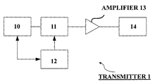
An infrared transmitter according to an embodiment of the present invention will be described with reference to the accompanying drawings. FIG. 1 is a block diagram depicting a configuration example of the infrared transmitter according to the embodiment of the present invention. In FIG. 1, this transmitter 1 includes: a voltage-controlled oscillator (VCO) 10 that oscillates a carrier wave; a filter 11 that reduces a spurious signal; a controller 12 that adjusts a cutoff frequency of the filter 11 according to an oscillation frequency of the VCO 10; an amplifier 13 composed of an amplifying circuit that amplifies an output from the filter 11; and an signal converter 14 that transmits an infrared signal according to an output from the amplifier 13.
The VCO 10 includes: an oscillating circuit that oscillates a carrier wave of a frequency corresponding to a channel under use set with a setting unit (not shown); and a modulating circuit that modulates, with the carrier wave, a transmission signal received from a signal source (not shown). The frequency of the carrier wave oscillated by the VCO 10 is a frequency of the channel under use.
The filter 11 is composed of a filter circuit that reduces a spurious signal of the signal output from the VCO 10. The cutoff frequency of the filter circuit 11 is adjusted by the controller 12. Thus, the filter 11 is a filter circuit of which a characteristic can be adjusted according to, for example, a control signal from the controller 12.
The controller 12 is composed of a controlling circuit that adjusts the characteristic of the filter 11 to be most suitable for the oscillation frequency set for the VCO 10. The controller 12 is a circuit having a microcomputer that adjusts the cutoff frequency to make the characteristic of the filter 11 most suitable for the oscillation frequency set for the VCO 10.
The amplifier 13 is composed of the amplifying circuit that amplifies the signal output from the filter 11 and outputs the amplified signal to the signal converter 14.
The signal converter 14 is a circuit composed of an infrared light-emitting diode (IRLED) that converts the transmission signal amplified by the amplifier 13 into an infrared signal.
The filter 11 may be a low-pass filter that passes only frequency components equal to or lower than the cutoff frequency and eliminates frequency components higher than the cutoff frequency. The filter 11 may also be a band pass filter that passes only frequency components included in a certain frequency band defined by two cutoff frequencies, and eliminates frequency components not included therein.
The filter 11 may have a variable capacitance diode so that the cutoff frequency of the filter 11 can be adjusted in a non-step manner as the controller 12 adjusts the voltage applied to the variable capacitance diode.
In the transmitter 1, the VCO 10 oscillates the carrier wave corresponding to a transmission channel selected by a user. The characteristic of the filter 11 can be adjusted to have the cutoff frequency most suitable for the carrier frequency set for the VCO 10. Thus, a spurious signal of the transmission signal obtained by modulating the signal received from the signal source not shown (e.g., a sound signal via an electro-acoustic transducing element) with the carrier wave, can be effectively eliminated.
Therefore, the filter characteristic can be automatically set to be most suitable for reducing a spurious signal according to the transmission channel arbitrary selected by the user. As a result, spurious noise and interference can be effectively prevented upon use of the transmitter with which a number of channels can be used.
The infrared transmitter of the present invention described above in the embodiment of the present invention can be advantageously applied, for example, to the infrared wireless microphone with which a plurality of channels can be used.

Claims (4)

1. An infrared transmitter for transmitting a signal via an infrared ray, the infrared transmitter comprising:
a signal converter for converting the signal into an infrared signal;
an oscillator for oscillating a carrier frequency of the infrared signal;
a controller for adjusting a cutoff frequency of a filter according to the carrier frequency; and the filter provided between the oscillator and the signal converter, the filter having the cutoff frequency adjusted by the controller,
wherein the filter includes a variable capacitance diode so that the cutoff frequency is adjusted in a non-step manner as the controller adjusts a voltage applied to the variable capacitance diode, and
the signal converter comprises an infrared light-emitting diode (IRLED).
2. The infrared transmitter according to claim 1, wherein the filter is a low-pass filter.
3. The infrared transmitter according to claim 1, wherein the filter is a band pass filter.
4. The infrared transmitter according to claim 1, further comprising:
an amplifier which is coupled to an output of the filter and to an input of the signal converter and amplifies the filtered signal,
wherein the IRLED is configured to convert the signal amplified by the amplifier into the infrared signal.
US12/689,935 2009-01-20 2010-01-19 Infrared transmitter Expired - Fee Related US8320776B2 (en)

Applications Claiming Priority (2)

Application Number Priority Date Filing Date Title
JP2009010061A JP5289986B2 (en) 2009-01-20 2009-01-20 Infrared transmitter
JP2009-010061 2009-01-20

Publications (2)

Publication Number Publication Date
US20100183317A1 US20100183317A1 (en) 2010-07-22
US8320776B2 true US8320776B2 (en) 2012-11-27

Family

ID=42337030

Family Applications (1)

Application Number Title Priority Date Filing Date
US12/689,935 Expired - Fee Related US8320776B2 (en) 2009-01-20 2010-01-19 Infrared transmitter

Country Status (3)

Country Link
US (1) US8320776B2 (en)
JP (1) JP5289986B2 (en)
CN (1) CN101783704B (en)

Families Citing this family (7)

* Cited by examiner, † Cited by third party
Publication number Priority date Publication date Assignee Title
BRPI0613387A2 (en) 2005-07-08 2011-01-11 Biogen Idec Inc isolated antibody or antigen binding fragment thereof and its use, isolated polynucleotide, composition, vector, host cell, anti-sp35 antibody and method for producing the same, isolated polypeptide, in vitro method for reducing inhibition of axonal growth and in vitro method for inhibiting cone collapse growth
EP2205071B1 (en) * 2007-10-11 2015-07-22 Biogen MA Inc. Lingo-1 antagonists and trkb agonists for use in the treatment of glaucoma
WO2009061500A1 (en) * 2007-11-08 2009-05-14 Biogen Idec Ma Inc. Use of lingo-4 antagonists in the treatment of conditions involving demyelination
CA2729961C (en) 2008-07-09 2018-05-01 Biogen Idec Ma Inc. Li113, li62 variant co2, anti-lingo antibodies
US9796780B2 (en) 2012-05-14 2017-10-24 Biogen Ma Inc. LINGO-2 antagonists for treatment of conditions involving motor neurons
WO2016112270A1 (en) 2015-01-08 2016-07-14 Biogen Ma Inc. Lingo-1 antagonists and uses for treatment of demyelinating disorders
CN105141370B (en) * 2015-07-31 2017-08-25 宁波成电泰克电子信息技术发展有限公司 A kind of processing method of closely ultrahigh speed infrared transmitted signal

Citations (6)

* Cited by examiner, † Cited by third party
Publication number Priority date Publication date Assignee Title
US5161021A (en) * 1990-12-18 1992-11-03 Tsai Ching Yun Wireless video/audio signal or data transmission device and its remote control circuit
JPH1141120A (en) 1997-07-15 1999-02-12 Matsushita Electric Ind Co Ltd Transmission device
US20010021230A1 (en) * 1996-02-23 2001-09-13 Harris Corporation Current-controlled carrier tracking filter for improved spurious signal suppression
US6480699B1 (en) * 1998-08-28 2002-11-12 Woodtoga Holdings Company Stand-alone device for transmitting a wireless signal containing data from a memory or a sensor
US20040106380A1 (en) * 2002-09-03 2004-06-03 Iason Vassiliou Direct-conversion transceiver enabling digital calibration
US7193544B1 (en) * 2004-09-08 2007-03-20 Northrop Grumman Corporation Parallel, adaptive delta sigma ADC

Family Cites Families (13)

* Cited by examiner, † Cited by third party
Publication number Priority date Publication date Assignee Title
CN1162875A (en) * 1996-02-23 1997-10-22 哈里公司 Current-controlled carrier tracking filter for improved spurious signal suppression
JP3820631B2 (en) * 1996-06-06 2006-09-13 ソニー株式会社 Receiver
JP2000349560A (en) * 1999-03-31 2000-12-15 Matsushita Electric Ind Co Ltd Voltage controlled oscillator, FM signal light transmitter, FM signal light receiver, and FM signal light transmission system
JP2000307522A (en) * 1999-04-19 2000-11-02 Matsushita Electric Ind Co Ltd Optical transmission device and optical transmission device
CA2307536A1 (en) * 2000-05-04 2001-11-04 Surety Manufacturing And Testing Ltd. Fall restraint anchor
CN1193520C (en) * 2001-09-25 2005-03-16 义隆电子股份有限公司 A device that can adjust the carrier frequency of ultrasonic waves and infrared rays
JP3768940B2 (en) * 2002-09-11 2006-04-19 株式会社東芝 Optical transmitter and wavelength division multiplexing optical communication system using the same
JP3761528B2 (en) * 2003-03-12 2006-03-29 株式会社東芝 Optical transmission device and optical transmission method
JP2005175675A (en) * 2003-12-09 2005-06-30 Hitachi Kokusai Electric Inc Wireless transmission system
JP3819912B2 (en) * 2004-03-29 2006-09-13 株式会社東芝 Optical transmitter and optical communication system
US20060032703A1 (en) * 2004-07-30 2006-02-16 William Burdet Fall restraint device
WO2008010274A1 (en) * 2006-07-19 2008-01-24 Panasonic Corporation Visible light communication apparatus
JP2007228603A (en) * 2007-03-20 2007-09-06 Toshiba Corp Radio communication base station apparatus, radio signal optical transmission receiver, and radio signal optical transmission transceiver

Patent Citations (6)

* Cited by examiner, † Cited by third party
Publication number Priority date Publication date Assignee Title
US5161021A (en) * 1990-12-18 1992-11-03 Tsai Ching Yun Wireless video/audio signal or data transmission device and its remote control circuit
US20010021230A1 (en) * 1996-02-23 2001-09-13 Harris Corporation Current-controlled carrier tracking filter for improved spurious signal suppression
JPH1141120A (en) 1997-07-15 1999-02-12 Matsushita Electric Ind Co Ltd Transmission device
US6480699B1 (en) * 1998-08-28 2002-11-12 Woodtoga Holdings Company Stand-alone device for transmitting a wireless signal containing data from a memory or a sensor
US20040106380A1 (en) * 2002-09-03 2004-06-03 Iason Vassiliou Direct-conversion transceiver enabling digital calibration
US7193544B1 (en) * 2004-09-08 2007-03-20 Northrop Grumman Corporation Parallel, adaptive delta sigma ADC

Also Published As

Publication number Publication date
CN101783704A (en) 2010-07-21
CN101783704B (en) 2014-06-11
JP2010171524A (en) 2010-08-05
US20100183317A1 (en) 2010-07-22
JP5289986B2 (en) 2013-09-11

Similar Documents

Publication Publication Date Title
US8320776B2 (en) Infrared transmitter
US6778814B2 (en) Wireless microphone apparatus and transmitter device for a wireless microphone
US7830214B2 (en) Adjustable chaotic signal generator using pulse modulation for ultra wideband (UWB) communications and chaotic signal generating method thereof
CN101416429B (en) System and method for zero intermediate frequency filtering of communication information in a wireless network
JP2012254003A (en) Wireless power data transmission system, power transmission apparatus, and power reception apparatus
EP1863183A4 (en) TRANSMISSION APPARATUS, COMMUNICATION DEVICE, AND MOBILE WIRELESS UNIT
US7049902B2 (en) Tunable high-order bessel low pass filter
JP2015198282A (en) acoustic FM transmitter
RU26714U1 (en) MULTIFUNCTIONAL COMMUNICATION SYSTEM FUNCTIONING UNDER THE CONDITIONS OF EXPOSURE TO UNCERTAIN INTERFERENCE WITH A LIMITED MIDDLE POWER
US20080176524A1 (en) FM transmitter device
JP3753050B2 (en) Communication device
KR20000072891A (en) Transmitter and receiver of remote controlling signal
JP2003078433A (en) Frequency conversion circuit
JP2004040561A (en) Transceiver
KR200222669Y1 (en) Time delay device
JP2010136121A (en) Wireless microphone
KR100756418B1 (en) Stereo audio signal transmitter and receiver using power line
JP2007208718A (en) Switching power supply
KR200220461Y1 (en) Circuit for voltage controlled oscillator in cordless telephone
KR100720376B1 (en) Multichannel Audio Signal Transmitter and Receiver Using Power Line
JPH02284533A (en) Infrared remote controller
RU16957U1 (en) TELEMETRIC RADIO STATION
RU26255U1 (en) VIBRATION PUMP
KR20060049193A (en) Signal transmission system and signal transmission method
JPH04124922A (en) Light transmitting equipment

Legal Events

Date Code Title Description
AS Assignment

Owner name: KABUSHIKI KAISHA AUDIO-TECHNICA, JAPAN

Free format text: ASSIGNMENT OF ASSIGNORS INTEREST;ASSIGNOR:HARIMA, TATSUJI;REEL/FRAME:023812/0370

Effective date: 20100108

STCF Information on status: patent grant

Free format text: PATENTED CASE

FPAY Fee payment

Year of fee payment: 4

FEPP Fee payment procedure

Free format text: MAINTENANCE FEE REMINDER MAILED (ORIGINAL EVENT CODE: REM.); ENTITY STATUS OF PATENT OWNER: LARGE ENTITY

LAPS Lapse for failure to pay maintenance fees

Free format text: PATENT EXPIRED FOR FAILURE TO PAY MAINTENANCE FEES (ORIGINAL EVENT CODE: EXP.); ENTITY STATUS OF PATENT OWNER: LARGE ENTITY

STCH Information on status: patent discontinuation

Free format text: PATENT EXPIRED DUE TO NONPAYMENT OF MAINTENANCE FEES UNDER 37 CFR 1.362

FP Lapsed due to failure to pay maintenance fee

Effective date: 20201127