US831797A - Dining-table. - Google Patents
Dining-table. Download PDFInfo
- Publication number
- US831797A US831797A US29628906A US1906296289A US831797A US 831797 A US831797 A US 831797A US 29628906 A US29628906 A US 29628906A US 1906296289 A US1906296289 A US 1906296289A US 831797 A US831797 A US 831797A
- Authority
- US
- United States
- Prior art keywords
- pin
- lever
- frame
- leaf
- dining
- Prior art date
- Legal status (The legal status is an assumption and is not a legal conclusion. Google has not performed a legal analysis and makes no representation as to the accuracy of the status listed.)
- Expired - Lifetime
Links
Images
Classifications
-
- A—HUMAN NECESSITIES
- A47—FURNITURE; DOMESTIC ARTICLES OR APPLIANCES; COFFEE MILLS; SPICE MILLS; SUCTION CLEANERS IN GENERAL
- A47B—TABLES; DESKS; OFFICE FURNITURE; CABINETS; DRAWERS; GENERAL DETAILS OF FURNITURE
- A47B35/00—Tables combined with ironing-boards, washers, wringers, or the like
Definitions
- My invention relates to new and useful improvements in dining-tables, and more particularly to that class wherein the table-top is adapted to rotate upon its sup mrting-base, and my object is to provide means for taking up the wearu on the table-bearing.
- the invention consists of a frame having a' ball-bearing upon the center thereof which supports a circular table-top having a central pivot-pin which is provided with novel means for tightening it.
- the invention also consists in further novel construction and combination of parts hereinafter more fully described and claimed.
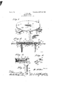
- FIG. 1 is a perspective view of my improved table.
- Fig. 2 is a central vertical section therethrough.
- Fig. 3 is a transverse section through one of the leaves and the ad joining parts of the table.
- Fig. 4 is a detail View of the adjusting-lever; and
- Fig. 5 is a similar view of the pivot-pin.
- l is a rectangular frame supported on legs 2, and secured to this frame are parallel uide-strips 3, arranged in pairs and extendlng laterally from the frame 1.
- These guidestrips are grooved, as shown at 4, for the reception of longitudinally-arranged cleats 5 upon the side edges of leaves 6.
- These leaves are adapted to be slid between the pairs of guidestrips'and have downwardly-projecting por tions 7 at their front ends, whereby they may be readily grasped.
- each leaf is less than the thickness of the guidestrips 3, and therefore when the leaf is in position between the guides a sufficient space is leftbetween the top of the leaf and the upper ed es of its guide-strips 3 to enable a plate, knife, fork, &c., to be placed upon the leaf while said leaf is in position between its guidestrips.
- a Wearplate- 1 l is secured upon the upper face of this block by means of the bolts 9, and said Wearplate has a centrally-disposed downwardlyprojecting lug 12, which projects through the center of block Sand has a passage through it.
- Plate 11 is also provided with a race 13, which is concentric with the lug 12, said race being adapted to receive a series of balls 1.4, which project into a similar race formed within the wear-plate 15.
- This wear-plate is secured to the lower surface of a circular tabletop 16, and at the center thereof a lug 17 projects upward from wear-plate 15 and through the center of the table-top, and this lug has a passage through it for the reception of the head 18 and a portion of the stem 19 of a pivot-pin.
- Said pin extends downward through lug 12 and through the strip 10 and has op)ositely-arrangcd grooves or recesses 20 wit llll it, adapted to receive the forked end 21 of a lever 22.
- This lever has one face curved so as to give the same a rocker-like appearance, and the other end of the lever is likewise forked, as shown at 23, and embraces one of the bolts 9.
- said leaf is then slid under the table-top 16, there being sufficient room between the leaf and the table-top to accommodate the articles placed on the leaf.
- the leaves are drawn outward and the food to be served is placed 'ing from the rear end of the leaf 6, mounted on the table-top 16, and anyone of the persons can quickly serve himself simply by grasping said table-top and rotating it until any dish desired'is brought within convenient reach.
- I preferably provide thereon at regular intervals and adjacent the periphery of the top a series of grips or knobs 27 which may be of any size and suitably ornamented.
- said pin headed at one end and slidably extending through both members with its head in contact With one of said members, said pin having a recess in the other end, a lever fulcrume'd on the other of said membersand engaging in said recess and means for adjusting said lever to slide the pin vertically whereby the rotatable member is drawn toward the frame member.
Description
No- 831,797. I PATENTED SEPT. 25, 1906.
' M. MILLER.
DINING TABLE.
APPLICATION FILED JAN. 16, 1906.
M ARK MILLER, OF HUG HESTON, WVEST VIRGINIA.
DINING-TABLE.
Specification of Letters Patent.
Patented Sept. 25, 1906.
Application filed January 16,1906. Serial I10. 296,289.
To all whom it HI/[LII] concern:
Be it known that 1, MARK MILLER, a citizen of the United States, residing at llugheston, in the county of Kanawha and State of est Virginia, have invented certain new and useful Improvements in Dining-'lablcs; and I do hereby declare the following to be a full, clear, and exact description of the invention, such as will enable others skilled in the art to which it appertains to make and use the same.
My invention relates to new and useful improvements in dining-tables, and more particularly to that class wherein the table-top is adapted to rotate upon its sup mrting-base, and my object is to provide means for taking up the wearu on the table-bearing.
Vith the alioveand other objects in view the invention consists of a frame having a' ball-bearing upon the center thereof which supports a circular table-top having a central pivot-pin which is provided with novel means for tightening it.
The invention also consists in further novel construction and combination of parts hereinafter more fully described and claimed.
In the accompanying drawings 1 have shown the preferred form of my invention, and in said drawings Figure 1 is a perspective view of my improved table. Fig. 2 is a central vertical section therethrough. Fig. 3 is a transverse section through one of the leaves and the ad joining parts of the table. Fig. 4 is a detail View of the adjusting-lever; and Fig. 5 is a similar view of the pivot-pin.
Referring to the figures by numerals of reference, l is a rectangular frame supported on legs 2, and secured to this frame are parallel uide-strips 3, arranged in pairs and extendlng laterally from the frame 1. These guidestrips are grooved, as shown at 4, for the reception of longitudinally-arranged cleats 5 upon the side edges of leaves 6. These leaves are adapted to be slid between the pairs of guidestrips'and have downwardly-projecting por tions 7 at their front ends, whereby they may be readily grasped. The thickness of each leaf is less than the thickness of the guidestrips 3, and therefore when the leaf is in position between the guides a sufficient space is leftbetween the top of the leaf and the upper ed es of its guide-strips 3 to enable a plate, knife, fork, &c., to be placed upon the leaf while said leaf is in position between its guidestrips.
Secured between the intersecting portions of the guidestrips 3 1s a supporting-block 8,
which is held in place by means of bolts 9, ex-
tending downward through a cross-strip 10, which is fastened to two of the cleats 3 and is held by nuts in the usual manner. A Wearplate- 1 l is secured upon the upper face of this block by means of the bolts 9, and said Wearplate has a centrally-disposed downwardlyprojecting lug 12, which projects through the center of block Sand has a passage through it. Plate 11 is also provided with a race 13, which is concentric with the lug 12, said race being adapted to receive a series of balls 1.4, which project into a similar race formed within the wear-plate 15. This wear-plate is secured to the lower surface of a circular tabletop 16, and at the center thereof a lug 17 projects upward from wear-plate 15 and through the center of the table-top, and this lug has a passage through it for the reception of the head 18 and a portion of the stem 19 of a pivot-pin. Said pin extends downward through lug 12 and through the strip 10 and has op)ositely-arrangcd grooves or recesses 20 wit llll it, adapted to receive the forked end 21 of a lever 22. This lever has one face curved so as to give the same a rocker-like appearance, and the other end of the lever is likewise forked, as shown at 23, and embraces one of the bolts 9. The nut of said bolt overlaps said forked end of the lever, and by screwing said nut upon its bolt the lever will be pressed toward the strip 10, and this opposite forked end will be rocked or swung down ward, thereby drawing the pivot-pin longitudinallyand tightening the bearing of the tabetween said guide-strips.
In using the table herein described a plate, knife, fork, &c., is placed on each leaf 6, and
said leaf is then slid under the table-top 16, there being sufficient room between the leaf and the table-top to accommodate the articles placed on the leaf. After persons have been seated at the table the leaves are drawn outward and the food to be served is placed 'ing from the rear end of the leaf 6, mounted on the table-top 16, and anyone of the persons can quickly serve himself simply by grasping said table-top and rotating it until any dish desired'is brought within convenient reach. In order to facilitate the rotation of the table-top, I preferably provide thereon at regular intervals and adjacent the periphery of the top a series of grips or knobs 27 which may be of any size and suitably ornamented.
It will be understood that by using a table such as herein described each person can serve himself, and therefore the services of Waiters may be dispensed with,
What I claim is 1. In a table, a frame member, a rotatable top member, supported thereby, a pivot-pin.
headed at one end and slidably extending through both members with its head in contact With one of said members, said pin having a recess in the other end, a lever fulcrume'd on the other of said membersand engaging in said recess and means for adjusting said lever to slide the pin vertically whereby the rotatable member is drawn toward the frame member.
2 In a table, a frame member, a plate secured to said frame, a table-top above said frame, a plate secured to said top and extending therethrough, said plates havingreg,
istering vertical openings therethrough, a
headed pivot-pin slidably disposed through said openings, said pin having oppositely-disposed recesses in its free end, a forked lever fulcrumed on the one of saidplates next to the recessed end of said pin, the forked portions at one ear] thereof engaging the recesses in the pin and means engaging the opposite end of said lever to rock the lever to slide the pin vertically, whereby the table-top will be drawn toward the frame member.
3'. The combination with a table-frame and a rotatable top therefor, of a pivot-pin disposed through said top and frame, said pin having a head at one end and recesses at its opposite end, an elongated lever having one of its faces curved to form a fulcrum, s id lever being forked at each end, the'fork members at one end engaging the recesses in the pin and means carried by the frame to adjustably engage the opposite forked end of the lever the fulcrum portion of the lever at the same time bearing against a part of the frame whereby the pin may be longitudinally adjusted to draw the top toward the frame.
In testimony whereof I have signed my name to this specification in the presence of two subscribing witnesses.
MARK MILLER. Witnesses:
C. F. HUDDLEsToN, W. 'M. BAULING.
Priority Applications (1)
| Application Number | Priority Date | Filing Date | Title |
|---|---|---|---|
| US29628906A US831797A (en) | 1906-01-16 | 1906-01-16 | Dining-table. |
Applications Claiming Priority (1)
| Application Number | Priority Date | Filing Date | Title |
|---|---|---|---|
| US29628906A US831797A (en) | 1906-01-16 | 1906-01-16 | Dining-table. |
Publications (1)
| Publication Number | Publication Date |
|---|---|
| US831797A true US831797A (en) | 1906-09-25 |
Family
ID=2900272
Family Applications (1)
| Application Number | Title | Priority Date | Filing Date |
|---|---|---|---|
| US29628906A Expired - Lifetime US831797A (en) | 1906-01-16 | 1906-01-16 | Dining-table. |
Country Status (1)
| Country | Link |
|---|---|
| US (1) | US831797A (en) |
Cited By (8)
| Publication number | Priority date | Publication date | Assignee | Title |
|---|---|---|---|---|
| US2720372A (en) * | 1953-05-22 | 1955-10-11 | Gordon D Gowan | Swivel adapter for mounting a camera on a tripod |
| US4564091A (en) * | 1983-06-16 | 1986-01-14 | Coneglio August F | Writing board |
| US4709641A (en) * | 1986-08-18 | 1987-12-01 | The Pilliod Cabinet Company | Adjustable table structure |
| US4715295A (en) * | 1985-07-26 | 1987-12-29 | Hill-Rom Company, Inc. | Overbed table |
| US20080153611A1 (en) * | 2002-02-25 | 2008-06-26 | Carlin Ghahraman | Four dimensional billiards |
| US20080223801A1 (en) * | 2006-05-18 | 2008-09-18 | Scot Krempa | Food storage container organizer |
| US8100062B1 (en) * | 2009-01-13 | 2012-01-24 | Maria-Lucia Anghel | Expandable table |
| US20230331464A1 (en) * | 2022-04-13 | 2023-10-19 | Joan Bishop | Cake Enclosure |
-
1906
- 1906-01-16 US US29628906A patent/US831797A/en not_active Expired - Lifetime
Cited By (8)
| Publication number | Priority date | Publication date | Assignee | Title |
|---|---|---|---|---|
| US2720372A (en) * | 1953-05-22 | 1955-10-11 | Gordon D Gowan | Swivel adapter for mounting a camera on a tripod |
| US4564091A (en) * | 1983-06-16 | 1986-01-14 | Coneglio August F | Writing board |
| US4715295A (en) * | 1985-07-26 | 1987-12-29 | Hill-Rom Company, Inc. | Overbed table |
| US4709641A (en) * | 1986-08-18 | 1987-12-01 | The Pilliod Cabinet Company | Adjustable table structure |
| US20080153611A1 (en) * | 2002-02-25 | 2008-06-26 | Carlin Ghahraman | Four dimensional billiards |
| US20080223801A1 (en) * | 2006-05-18 | 2008-09-18 | Scot Krempa | Food storage container organizer |
| US8100062B1 (en) * | 2009-01-13 | 2012-01-24 | Maria-Lucia Anghel | Expandable table |
| US20230331464A1 (en) * | 2022-04-13 | 2023-10-19 | Joan Bishop | Cake Enclosure |
Similar Documents
| Publication | Publication Date | Title |
|---|---|---|
| US831797A (en) | Dining-table. | |
| US1754094A (en) | Self-serving tray | |
| US126833A (en) | Improvement in dough rollers and cutters | |
| US556566A (en) | Half to john jolly | |
| US466303A (en) | Schied | |
| US490286A (en) | Self-servxng table | |
| US79543A (en) | Improved vegetable-server | |
| US1472348A (en) | Rotating server | |
| US327032A (en) | Rotary tray | |
| US924938A (en) | Revolving tray. | |
| US976205A (en) | Hat and clothes rack. | |
| US1114129A (en) | Revolving table. | |
| US1400209A (en) | Sebvee fob | |
| US615130A (en) | Drawing-table | |
| US1642094A (en) | Caster attachment for trunks | |
| US779402A (en) | Glass base for furniture. | |
| US705903A (en) | Table. | |
| US891829A (en) | Adjustable roller portable stand. | |
| US670357A (en) | Flower-stand. | |
| US1192746A (en) | Desk. | |
| US1226134A (en) | Circular extension-table. | |
| US529178A (en) | Carl h | |
| US148174A (en) | Improvement in game-tables | |
| US776232A (en) | Revolving stand. | |
| US558289A (en) | Coffee-mill holder |