US831780A - Lumber-jack. - Google Patents
Lumber-jack. Download PDFInfo
- Publication number
- US831780A US831780A US29001805A US1905290018A US831780A US 831780 A US831780 A US 831780A US 29001805 A US29001805 A US 29001805A US 1905290018 A US1905290018 A US 1905290018A US 831780 A US831780 A US 831780A
- Authority
- US
- United States
- Prior art keywords
- section
- jack
- lifting
- handle
- transmitting
- Prior art date
- Legal status (The legal status is an assumption and is not a legal conclusion. Google has not performed a legal analysis and makes no representation as to the accuracy of the status listed.)
- Expired - Lifetime
Links
- 230000036461 convulsion Effects 0.000 description 1
- 239000002184 metal Substances 0.000 description 1
Images
Classifications
-
- B—PERFORMING OPERATIONS; TRANSPORTING
- B66—HOISTING; LIFTING; HAULING
- B66F—HOISTING, LIFTING, HAULING OR PUSHING, NOT OTHERWISE PROVIDED FOR, e.g. DEVICES WHICH APPLY A LIFTING OR PUSHING FORCE DIRECTLY TO THE SURFACE OF A LOAD
- B66F15/00—Crowbars or levers
Definitions
- This invention relates to lumber-j acks, and is more particularly an improvement in the lumber-jack for which I have applied for Letters Patent under Serial No. 262,798, and has for its objects to adapt the above-mentioned jack to a greater variety of circumstances, as when heavy timbers have to be raised from the ground and loaded on trucks and when trucks of varying heights are used in the same mill.
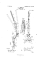
- Fig. '2 is a front view of the timbertongs mounted thereon and showing one hook thereof in position for use and the other hook in the position in which they are normally kept.
- Fig. 3 is a vertical longitudinal section of the handle-adjusting box.
- Fig. 1 is a side view of my improved lumber-j ack.
- Fig. '2 is a front view of the timbertongs mounted thereon and showing one hook thereof in position for use and the other hook in the position in which they
- FIG. 4 is a plan of the lumberjack.
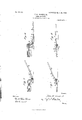
- Figs. 5 and 6 are two views of the jack in operation when used for high trucks, and Figs' 7 and S are similar views of the jack in position for using with very low trucks or for raising timbers directly from the ground.
- This improved lumber-jack is mounted on the axle 1, on which are journaled the two wheels 2, and consists of a lifting-section 3, having a bolster or cross-head 4, secured to its end, and an upper bolster or cross-head 5; a transmitting-section 6, extending rearward from the axle 1 and having the adjusting-box 7 secured to its end, and a handle 8, adjustably mounted in box 7 and having the telescopic extension 9 mounted thereon.
- the lumber-jack is also provided with a swinging leg 10, hinged to the lifting portion 3 and having a sharpened point adapted to dig into the supporting-ground as the liftingsection 3 is raised, and with a pair of timberhooks 11 loosely hung from the loop 12', secured to the center of the lower bolster or cross-head 1.
- this improved lumber-jack differs from my original jack in that the handle is telescopic and is vertically adjustable with regard to the rest of the jack, that the bolster is made in two parts, the upper portion having horizontal motion on the lower portion, and the timber-hooks which are secured to the lower bolster.
- the adjusting-box 7 is formed of metal.
- the sides thereof are continuous with the straps which form the sides of the transmit ting-section 6, and is therefore really a part of said section 6 and forms a socket on the end thereof.
- Two or more cross-pins 13 extend across-the space between the sides of the box 7.
- the handle-section S enters the open end of the box 7 and is provided at its end with a shoe 1 1, having a notch 15 in its upper surface adapted to engage any one of the pins 13.
- the said handle 8 and shoe 1 1 are slidably pivoted by means of the pin 16, which slides in the longitudinal slot 17 in the sides of the box 7 Referring to Fig. 3, the position of the handle in the adj Listing-box is the same as that shown in Figs.
- Fig. 1 the dotted lines indicate the ex: treme positions of the lumber-jack when it is used as above. If, however, it is desired to use the jack for a lower load, the handle 8 is slightly lifted at its end so that the shoe 14 is free from the pin 1 3. Then the handle is pulled so that the pin 16 slides in the slot 17. In this position the handle is unfasteued from the jack, and in order to refasten it into the desired adjusted position the imier end. is raised so that the notch .15 therein will engage whichever one of the other pins 13 it is desired and is then pushed so that the pin 16 slides back in the slot 17, and the handle is then adjusted in the box.
- Figs. 7 and S the handle is shown in the extreme adjustment for raising very low loads or for using the timber-tongs on heavy timbers lying flat on the ground.
- the handle 8 is rounded except near the box 7, and the metallic tube 9 is slid thereover.
- the pin 18 passes through the tube 9 and the handle 8. Two or more holes are provided in the tube 9, into which the pin 18 may be inserted by moving the tube 9 outward along the handle 8. I am thus able to loads without increasing the number of. men
- the timber-tongs 11 consists of two separate bent hooks, one being the reverse of the other, and each having a hole through which the loop 12 passes, said loop being secured to the lower bolster 4.
- the bolster 4 is also provided with small side hooks 19, over which the ends of the tongs 11 are hung when not in use, thus removing them entirely out of the way.
- the end of the leg 10 is sharpened, as above mentioned, so that in its use if the load is too great for the man working the jack to raise easily he can by loosening the leg 10 and j erking down on the handle raise the load a short distance and the leg will hold it in that position, and by continuing the operation the load can be raised the entire distance.
- the leg in this case allows the laborer to raise the load by a series of jerks in a manner very similar to a pump.
- 'the mode of using my jack in raising timbers from the ground is, first, to adjust the handle to its lowest positionthat is to say, so that its inner end engages the highest pin 13 in the box 7next to unloosen the tongs 11 from the hooks 19 on the bolster 4, next to apply said tongs to the sides of the end of the timber, as shown in Fig. 7, next to raise the timber to the position shown in Fig. 8, next to block the timber up in said position and unloosen the tongs, next to rehang the tongs 11 on the hooks 19, next to insert the bolster 5 under the raised end of the timber, and thus raise the timber to a sufficient height to insert the truck thereunder.
- a lifting-jack the combination of a lever having a lifting-section, and a transmitting-section; with a wheeled fulcrum for the lever adjacent the junction of said lifting and transmitting sections; a socket formed 5 on. the end of said transmitting-section; a handle-section entering said socket; and a series of pins secured within said socket, transversely thereof, and any one of which is adapted to be engaged by the end of said handle-section.
- a lifting-jack the combination of a lever having a lifting-section, and a transmitting-section; with a wheeled fulcrum for the lever adjacent the junction of said lifting and transmitting sections; a socket formed on the end of said transmitting-section; a shoe slidably pivoted within said socket and having a notch at its end; a handle-section secured to said shoe; and a series of pins secured within said socket, transversely thereof, and any one of which is adapted to be engaged by the notch in said shoe.
- a lifting-jack the combination of a lever having a lifting-section, and a transmitting-section; with a wheeled fulcrum for I the lever adjacent the junction of said lifting and transmitting sections; a socket formed on the end of said transmitting-section and a handle-section vertically adjustable in said socket.
- a lifting-jack the combination of a lever having a lifting-section and a transmitting-section; with a wheeled fulcrum for the lever adjacent the junction of said lifting and transmitting sections; a socket formed on the end of said transmitting-section; and a handle-section angularly adjustable in a vertical plane in said socket.
- a lifting-jack the combination of a lever having a lifting-section, and a transmitting-section; with a wheeled fulcrum for the lever adjacent the junction of said lifting and transmitting sections; a socket formed on the end of said transmitting-section'and a telescopic handle-section fitting adjustably in said socket.
- a lifting-jack the combination of a lever having a lifting-section, and a transmitting-section; with means secured to said lifting-section for engaging the article to be lifted; a wheeled fulcrum for the lever adjacent the junction of said lifting and transmitting sections, and a handle-section ex- IIO tending from said transmitting-section at a vertically-adjustable angle.
- a lifting-jack the combination of a lever having a lifting-section, and a transmitting-section; with means secured to said lifting-section for engaging the article to be lifted; a wheeled fulcrum for the lever adjacent the junction of said lifting and transmitting sections; a socket formed on the end of said transmitting-section; a handle-section entering said socket; and means within said socket for adjustably connecting said handle-section thereto.
- a lifting-jack the combination of a lever having a lifting-section, and a transmitting-section; with tongs secured to said lifting-section and adapted to engage the article to be lifted; a wheeled fulcrum for the lever adjacent the junction of said lifting and transmitting sections; a socket formed on the end of said transmitting-section; a handlesection entering said socket; and means Witliin said socket for adjustably connecting said handle-section thereto.
Landscapes
- Life Sciences & Earth Sciences (AREA)
- Engineering & Computer Science (AREA)
- Geology (AREA)
- Mechanical Engineering (AREA)
- Structural Engineering (AREA)
- Forms Removed On Construction Sites Or Auxiliary Members Thereof (AREA)
Description
No. 831,780. PATENTED SEPT. 25, 1906. J. M. FERRIS'S, JR.
LUMBER JACK. APPLICATION P-ILED DEC. 2. 1905.
2 SHEETS-SHEET 1.
WUQ/YWOZ @156 Err/b": fr.
I ins Max ms PETERS co., WASHINGTON, n. c.
72 Q.%:Z WX
No. 831,780. PATENTED SEPT. 25, 1906. J. M. FBRRISS, JR. LUMBER JACK.
APPLICATION FILED D110. 2. 1905.
2 SHEETS-SHEET 2.
r wuc/wioz Wilma om: z? 62% WW ifl/ zgamy THE NORRIS PETERS can, WASHINGTON, n. c.
JOHN M. FERRISS, JR, OF TACOMA, ASHINGTON.
LUMBER-JACK.
Specification of Letters Patent.
Patented. Sept. 25, 1906.
Application filed December 2,1905. Serial No. 290,018.
To all whont it may concern.-
Be it known that I, J OHN M. FERRIss, J r., a citizen of the United States of America, residing at Tacoma, in the county of Pierce and State of IVashington, have invented certain new and useful Improvements in Lumber- Jacks, of which the following is a specification, reference being had therein to the accompanying drawings.
This invention relates to lumber-j acks, and is more particularly an improvement in the lumber-jack for which I have applied for Letters Patent under Serial No. 262,798, and has for its objects to adapt the above-mentioned jack to a greater variety of circumstances, as when heavy timbers have to be raised from the ground and loaded on trucks and when trucks of varying heights are used in the same mill. I attain these objects by the devices illustrated in the accompanying drawings, in which- Figure 1 is a side view of my improved lumber-j ack. Fig. '2 is a front view of the timbertongs mounted thereon and showing one hook thereof in position for use and the other hook in the position in which they are normally kept. Fig. 3 is a vertical longitudinal section of the handle-adjusting box. Fig. 4 is a plan of the lumberjack. Figs. 5 and 6 are two views of the jack in operation when used for high trucks, and Figs' 7 and S are similar views of the jack in position for using with very low trucks or for raising timbers directly from the ground.
Similar numerals of reference refer to similar parts throughout the several views.
This improved lumber-jack is mounted on the axle 1, on which are journaled the two wheels 2, and consists of a lifting-section 3, having a bolster or cross-head 4, secured to its end, and an upper bolster or cross-head 5; a transmitting-section 6, extending rearward from the axle 1 and having the adjusting-box 7 secured to its end, and a handle 8, adjustably mounted in box 7 and having the telescopic extension 9 mounted thereon. The lumber-jack is also provided with a swinging leg 10, hinged to the lifting portion 3 and having a sharpened point adapted to dig into the supporting-ground as the liftingsection 3 is raised, and with a pair of timberhooks 11 loosely hung from the loop 12', secured to the center of the lower bolster or cross-head 1. It will, therefore, be seen that this improved lumber-jack differs from my original jack in that the handle is telescopic and is vertically adjustable with regard to the rest of the jack, that the bolster is made in two parts, the upper portion having horizontal motion on the lower portion, and the timber-hooks which are secured to the lower bolster.
The adjusting-box 7 is formed of metal. The sides thereof are continuous with the straps which form the sides of the transmit ting-section 6, and is therefore really a part of said section 6 and forms a socket on the end thereof. Two or more cross-pins 13 extend across-the space between the sides of the box 7. The handle-section S enters the open end of the box 7 and is provided at its end with a shoe 1 1, having a notch 15 in its upper surface adapted to engage any one of the pins 13. The said handle 8 and shoe 1 1 are slidably pivoted by means of the pin 16, which slides in the longitudinal slot 17 in the sides of the box 7 Referring to Fig. 3, the position of the handle in the adj Listing-box is the same as that shown in Figs. 1, 5, and 6 and is adapted for use when the jack is to be used for loading or unloading from a high level. In Fig. 1 the dotted lines indicate the ex: treme positions of the lumber-jack when it is used as above. If, however, it is desired to use the jack for a lower load, the handle 8 is slightly lifted at its end so that the shoe 14 is free from the pin 1 3. Then the handle is pulled so that the pin 16 slides in the slot 17. In this position the handle is unfasteued from the jack, and in order to refasten it into the desired adjusted position the imier end. is raised so that the notch .15 therein will engage whichever one of the other pins 13 it is desired and is then pushed so that the pin 16 slides back in the slot 17, and the handle is then adjusted in the box.
In Figs. 7 and S the handle is shown in the extreme adjustment for raising very low loads or for using the timber-tongs on heavy timbers lying flat on the ground. By means of this adjustment of the handle relative to the rest of the jack I am able to apply the bolster end under loads at three different heights from the ground without altering the height or extent of motion of the handle end.
The handle 8 is rounded except near the box 7, and the metallic tube 9 is slid thereover. The pin 18 passes through the tube 9 and the handle 8. Two or more holes are provided in the tube 9, into which the pin 18 may be inserted by moving the tube 9 outward along the handle 8. I am thus able to loads without increasing the number of. men
working on the jack by suitably moving the tube 9 outward along the handle 8.
In using my lumber-jack on trucks having very long loads, such as ladder-timbers, I find that it is sometimes convenient to apply the jack sidewise under the load instead of inserting it under the end on account of the great flexibility of the timbers comprising the load, and I have therefore devised the split bolster,'(illustrated especially in Figs. 1 and 4,) in which the lower bolster 4; corresponds with the similar bolster in my above-mentioned application and to and above which is pivotally secured the upper bolster 5. Since in ordinary use the bolster 5 will lie directly on the bolster 4, I am able to reduce the length of said bolster 4, as plainly shown in the drawings.
The timber-tongs 11 consists of two separate bent hooks, one being the reverse of the other, and each having a hole through which the loop 12 passes, said loop being secured to the lower bolster 4. The bolster 4 is also provided with small side hooks 19, over which the ends of the tongs 11 are hung when not in use, thus removing them entirely out of the way.
The end of the leg 10 is sharpened, as above mentioned, so that in its use if the load is too great for the man working the jack to raise easily he can by loosening the leg 10 and j erking down on the handle raise the load a short distance and the leg will hold it in that position, and by continuing the operation the load can be raised the entire distance. The leg in this case allows the laborer to raise the load by a series of jerks in a manner very similar to a pump.
Referring to Figs. 7 and 8, it will be seen that 'the mode of using my jack in raising timbers from the ground is, first, to adjust the handle to its lowest positionthat is to say, so that its inner end engages the highest pin 13 in the box 7next to unloosen the tongs 11 from the hooks 19 on the bolster 4, next to apply said tongs to the sides of the end of the timber, as shown in Fig. 7, next to raise the timber to the position shown in Fig. 8, next to block the timber up in said position and unloosen the tongs, next to rehang the tongs 11 on the hooks 19, next to insert the bolster 5 under the raised end of the timber, and thus raise the timber to a sufficient height to insert the truck thereunder.
Having now described my invention, what I claim is- 1. In a lifting-jack, the combination of a lever having a lifting-section, and a transmitting-section; with a wheeled fulcrum for the lever adjacent the junction of said lifting and transmitting sections; a socket formed on the end of said transmitting-section; and
a handle-section fitting adjustably in said handle-section entering said socket; and
means within said socket for adjustably connecting said handle-section thereto. 7
3. In a lifting-jack, the combination of a lever having a lifting-section, and a transmitting-section; with a wheeled fulcrum for the lever adjacent the junction of said lifting and transmitting sections; a socket formed 5 on. the end of said transmitting-section; a handle-section entering said socket; and a series of pins secured within said socket, transversely thereof, and any one of which is adapted to be engaged by the end of said handle-section.
4. In a lifting-jack, the combination of a lever having a lifting-section, and a transmitting-section; with a wheeled fulcrum for the lever adjacent the junction of said lifting and transmitting sections; a socket formed on the end of said transmitting-section; a shoe slidably pivoted within said socket and having a notch at its end; a handle-section secured to said shoe; and a series of pins secured within said socket, transversely thereof, and any one of which is adapted to be engaged by the notch in said shoe.
5. In a lifting-jack, the combination of a lever having a lifting-section, and a transmitting-section; with a wheeled fulcrum for I the lever adjacent the junction of said lifting and transmitting sections; a socket formed on the end of said transmitting-section and a handle-section vertically adjustable in said socket.
6. In a lifting-jack, the combination of a lever having a lifting-section and a transmitting-section; with a wheeled fulcrum for the lever adjacent the junction of said lifting and transmitting sections; a socket formed on the end of said transmitting-section; and a handle-section angularly adjustable in a vertical plane in said socket.
7. In a lifting-jack, the combination of a lever having a lifting-section, and a transmitting-section; with a wheeled fulcrum for the lever adjacent the junction of said lifting and transmitting sections; a socket formed on the end of said transmitting-section'and a telescopic handle-section fitting adjustably in said socket.
8. In a lifting-jack, the combination of a lever having a lifting-section, and a transmitting-section; with means secured to said lifting-section for engaging the article to be lifted; a wheeled fulcrum for the lever adjacent the junction of said lifting and transmitting sections, and a handle-section ex- IIO tending from said transmitting-section at a vertically-adjustable angle.
9. In a lifting-jack, the combination ofa lever having a lifting-section, and a transmitting-section; with means secured to said lifting-section for engaging the article to be lifted; a wheeled fulcrum for the lever adjacent the junction of said lifting and transmitting sections; a socket formed on the end of said transmitting-section; a handle-section entering said socket; and means within said socket for adjustably connecting said handle-section thereto.
10. In a lifting-jack, the combination of a lever having a lifting-section, and a transmitting-section; with tongs secured to said lifting-section and adapted to engage the article to be lifted; a wheeled fulcrum for the lever adjacent the junction of said lifting and transmitting sections; a socket formed on the end of said transmitting-section; a handlesection entering said socket; and means Witliin said socket for adjustably connecting said handle-section thereto.
In testimony whereof I aflix my signature in presence of two witnesses.
JOHN M. FERRISS, Jr. Witnesses:
M. H. COREY, M. A. VAN HoUsE.
Priority Applications (1)
| Application Number | Priority Date | Filing Date | Title |
|---|---|---|---|
| US29001805A US831780A (en) | 1905-12-02 | 1905-12-02 | Lumber-jack. |
Applications Claiming Priority (1)
| Application Number | Priority Date | Filing Date | Title |
|---|---|---|---|
| US29001805A US831780A (en) | 1905-12-02 | 1905-12-02 | Lumber-jack. |
Publications (1)
| Publication Number | Publication Date |
|---|---|
| US831780A true US831780A (en) | 1906-09-25 |
Family
ID=2900255
Family Applications (1)
| Application Number | Title | Priority Date | Filing Date |
|---|---|---|---|
| US29001805A Expired - Lifetime US831780A (en) | 1905-12-02 | 1905-12-02 | Lumber-jack. |
Country Status (1)
| Country | Link |
|---|---|
| US (1) | US831780A (en) |
Cited By (2)
| Publication number | Priority date | Publication date | Assignee | Title |
|---|---|---|---|---|
| US3254876A (en) * | 1964-01-29 | 1966-06-07 | Norman C Powell | Post removing device |
| US6015254A (en) * | 1995-12-19 | 2000-01-18 | Keeler; Michael E. | Snowmobile lift cart, and methods of constructing and utilizing same |
-
1905
- 1905-12-02 US US29001805A patent/US831780A/en not_active Expired - Lifetime
Cited By (2)
| Publication number | Priority date | Publication date | Assignee | Title |
|---|---|---|---|---|
| US3254876A (en) * | 1964-01-29 | 1966-06-07 | Norman C Powell | Post removing device |
| US6015254A (en) * | 1995-12-19 | 2000-01-18 | Keeler; Michael E. | Snowmobile lift cart, and methods of constructing and utilizing same |
Similar Documents
| Publication | Publication Date | Title |
|---|---|---|
| US2656058A (en) | Truck loading and unloading mechanism | |
| US831780A (en) | Lumber-jack. | |
| US623669A (en) | Truck | |
| US356443A (en) | Lifting-jack | |
| US265384A (en) | Hoisting-machine | |
| US489339A (en) | Device for raising loaded trucks | |
| US677920A (en) | Lifting-jack. | |
| US1426068A (en) | Automobile jack | |
| US37707A (en) | Improvement in lifting-jacks | |
| US922029A (en) | Combined skid and truck. | |
| US342816A (en) | Stove-truck | |
| US315871A (en) | Absignoe of two | |
| US956577A (en) | Lifting-jack. | |
| US394820A (en) | Wagon-jack | |
| US949435A (en) | Scale. | |
| US425682A (en) | Wagon-jack | |
| US232855A (en) | Philestee smith | |
| US303120A (en) | Lifting-jack | |
| US133728A (en) | Improvement in lifting-jacks | |
| US177125A (en) | Improvement in lifting-jacks | |
| US193931A (en) | Improvement in lifting-jacks | |
| US253964A (en) | Lifting-jack | |
| US321810A (en) | Wagon-jack | |
| US224819A (en) | Lifting-jack | |
| US1903115A (en) | Conveying jack |