US830588A - Attachment for straw-carriers. - Google Patents
Attachment for straw-carriers. Download PDFInfo
- Publication number
- US830588A US830588A US28707105A US1905287071A US830588A US 830588 A US830588 A US 830588A US 28707105 A US28707105 A US 28707105A US 1905287071 A US1905287071 A US 1905287071A US 830588 A US830588 A US 830588A
- Authority
- US
- United States
- Prior art keywords
- straw
- slats
- attachment
- carrier
- levers
- Prior art date
- Legal status (The legal status is an assumption and is not a legal conclusion. Google has not performed a legal analysis and makes no representation as to the accuracy of the status listed.)
- Expired - Lifetime
Links
- 239000000969 carrier Substances 0.000 title description 2
- 239000010902 straw Substances 0.000 description 8
- XEEYBQQBJWHFJM-UHFFFAOYSA-N Iron Chemical compound [Fe] XEEYBQQBJWHFJM-UHFFFAOYSA-N 0.000 description 2
- 239000000463 material Substances 0.000 description 2
- 229910011620 Lix My Inorganic materials 0.000 description 1
- 238000010276 construction Methods 0.000 description 1
- 229910052742 iron Inorganic materials 0.000 description 1
Images
Classifications
-
- B—PERFORMING OPERATIONS; TRANSPORTING
- B65—CONVEYING; PACKING; STORING; HANDLING THIN OR FILAMENTARY MATERIAL
- B65G—TRANSPORT OR STORAGE DEVICES, e.g. CONVEYORS FOR LOADING OR TIPPING, SHOP CONVEYOR SYSTEMS OR PNEUMATIC TUBE CONVEYORS
- B65G47/00—Article or material-handling devices associated with conveyors; Methods employing such devices
- B65G47/52—Devices for transferring articles or materials between conveyors i.e. discharging or feeding devices
- B65G47/66—Fixed platforms or combs, e.g. bridges between conveyors
Definitions
- This invention relates to improvements in straw-carriers ⁇ of that class in which the straw is elevated by an endless belt and which forms a part of threshing-machines.
- the especial object of my improvements is to provide means whereby the straw cannot be blown from the carrier or elevator while on its way from the machine to the strawstack.
- Theinvention which forms the subjectmatter of this application is adapted to be applied to various forms of endless conveyers and may therefore be used not only in connection with the manipulation of straw, but also for any other material which is being carried from one point to another over an endless conveyer and which is liable to be scattered by wind.
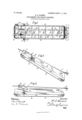
- Figure l is a top plan view of a carrier equipped with my improvements.
- Fig. 2 is a side elevation of the carrier, showing it in elevated position; and
- Fig. 3 is a side elevation showing the carrier in a horizontal position.
- A represents the side pieces or boards o the carrier, which are of any desired length and suitably spaced apart to form a chute or guide. Between the sides of which the straw is conveyed. At each end of these side boards is mounted a roller a/ a', and on the-spindle of one of these rollers is fixed a sprocketwheel 0,2, which may be driven from any suitable source and is usually driven by a sprocket-chain from the threshing-machine proper. Traveling over the rollers is an endless belt B, made of canvas usually and provided with spaced slats b on its outer surface. D represents a section of timber which is connected with or a part of the frame or body of the threshing-machine, the latter not being shown.
- slats C Connected with the piece D by the hinges d I:are two slats C, which extend longitudinally of the endless belt and are arranged above the latter, as clearly shown. If a wide carrier is needed, more slats may be used. Near .the free ends of these slats are secured clevises c', consisting of iron rods bent with their ends inserted in the slats so as to leave a space or slideway between a portion of the c evises and the upper side of the slats C.
- a transverse bar E Slidably arranged in this slideway is a transverse bar E, to the ends of which are secured crank-levers e, upon which are adjustably vmounted counterweights e2, the same being held upon the levers by set-screws e3.
- the levers are j ournaled in notches cut in the upper edge of the side pieces A and are held in place by straps a4.
- a pin 0,3 Projecting from the outer face of one of the side boards A is a pin 0,3, so positioned as to check the movement of the vertical portion of one of the crank-levers e', and thus limit their movement in one direction when the (livarrier is elevated in the position shown in
- the carrier proper is hingedly vconnected with the frame of the threshing-machine in any suitable manner, so that it may be elevated at dierent angles, as required in the practical operation of the machine.
- the slats C are made of light material and are of sui'licient Width to eectually cover a portion of straw on its way from the latter.
- An attachment for endless-conveyer frames consisting of slats arranged longitudinally of such frames and hinged at one end, and adjustable means for controlling the raising of the free ends of said slats relative to the conveyer-frame.
- said means consisting of a bar slidably arranged on said slats, and oounterweighted levers connected With said bar and journaled in said frame.
- An attachment for endless eonveyerframes consisting of slats hinged at one end and arranged longitudinally of said frame, means for supporting the free ends of said slats, said means consisting of a bar slidably arranged on said slats, levers connected with said bar, Weights adjustably mounted on said levers and means for limiting the movement of said levers in one direction.
Landscapes
- Engineering & Computer Science (AREA)
- Mechanical Engineering (AREA)
- Chain Conveyers (AREA)
Description
EATENTED sEET. 11, 1906. H. s. EANsoN. ATTACHMENT EOE STEAW .GAEEIEIEEI A APPLICATION FILED NOV.13.1905.
UNITED sTATEs PATENT oEEIoE.
Specification of Letters Patent.
Patented Sept. 11, 1.906.
Application filed November 13, 1905. Serial No. 287,071.
T0 @ZZ whom, t may concern:
Be it known that IHERBERT S. HANsoN, a citizen of the United States, residing at Caledonia, in the county of Boone and State of Illinois, have invented certain new and useful Improvements in Attachments for Straw-Carriers, ofv which the following is a specification.
This invention relates to improvements in straw-carriers` of that class in which the straw is elevated by an endless belt and which forms a part of threshing-machines.
The especial object of my improvements is to provide means whereby the straw cannot be blown from the carrier or elevator while on its way from the machine to the strawstack.
Theinvention which forms the subjectmatter of this application is adapted to be applied to various forms of endless conveyers and may therefore be used not only in connection with the manipulation of straw, but also for any other material which is being carried from one point to another over an endless conveyer and which is liable to be scattered by wind.
In the accompanying drawings, which form a part of this application, I have shown my invention as applied to a straw-carrier of simple construction and have illustrated the same in detail in the following views.
Figure l is a top plan view of a carrier equipped with my improvements. Fig. 2 is a side elevation of the carrier, showing it in elevated position; and Fig. 3 is a side elevation showing the carrier in a horizontal position.
Referring to the detailsv of the drawin s, A represents the side pieces or boards o the carrier, which are of any desired length and suitably spaced apart to form a chute or guide. between the sides of which the straw is conveyed. At each end of these side boards is mounted a roller a/ a', and on the-spindle of one of these rollers is fixed a sprocketwheel 0,2, which may be driven from any suitable source and is usually driven by a sprocket-chain from the threshing-machine proper. Traveling over the rollers is an endless belt B, made of canvas usually and provided with spaced slats b on its outer surface. D represents a section of timber which is connected with or a part of the frame or body of the threshing-machine, the latter not being shown.
Connected with the piece D by the hinges d I:are two slats C, which extend longitudinally of the endless belt and are arranged above the latter, as clearly shown. If a wide carrier is needed, more slats may be used. Near .the free ends of these slats are secured clevises c', consisting of iron rods bent with their ends inserted in the slats so as to leave a space or slideway between a portion of the c evises and the upper side of the slats C. Slidably arranged in this slideway is a transverse bar E, to the ends of which are secured crank-levers e, upon which are adjustably vmounted counterweights e2, the same being held upon the levers by set-screws e3. The levers are j ournaled in notches cut in the upper edge of the side pieces A and are held in place by straps a4.
Projecting from the outer face of one of the side boards A is a pin 0,3, so positioned as to check the movement of the vertical portion of one of the crank-levers e', and thus limit their movement in one direction when the (livarrier is elevated in the position shown in It will be understood that the carrier proper is hingedly vconnected with the frame of the threshing-machine in any suitable manner, so that it may be elevated at dierent angles, as required in the practical operation of the machine. The slats C are made of light material and are of sui'licient Width to eectually cover a portion of straw on its way from the latter. As the straw passes under the slats C it has a tendency to accumulate or pile up near the outer end of the carrier, and in order to prevent it from choking at this point I provide the counterweights above described, whi ch, coupled with the upward pressure from the accumulated straw, will permit the slats C to rise at this point, and thus allow the straw to pass beyond same to the stack. This movement of the slats is controlled in part by the position of the counterweights on the crank-levers and also by the angle at which the carrier is held, as will be readily understood.
Having thus described my invention, what I claim isl. An attachment for endless-conveyer frames, consisting of slats arranged longitudinally of such frames and hinged at one end, and adjustable means for controlling the raising of the free ends of said slats relative to the conveyer-frame.
2. An attachment for endless-conveyer frames consisting of slats hinged at one end rooV IIO
and arranged longitudinally of said frame, means for supporting the free ends of said slatsI said means consisting of a bar slidably arranged on said slats, and oounterweighted levers connected With said bar and journaled in said frame.
y 3. An attachment for endless eonveyerframes consisting of slats hinged at one end and arranged longitudinally of said frame, means for supporting the free ends of said slats, said means consisting of a bar slidably arranged on said slats, levers connected with said bar, Weights adjustably mounted on said levers and means for limiting the movement of said levers in one direction. 15 In testimony Whereot1 I ai'lix my signature in presence of tWo Witnesses.
HERBERT SA. HANSON.
Witnesses:
E. E. LICHTENBERG, v W. RJVICKERS,
Priority Applications (1)
| Application Number | Priority Date | Filing Date | Title |
|---|---|---|---|
| US28707105A US830588A (en) | 1905-11-13 | 1905-11-13 | Attachment for straw-carriers. |
Applications Claiming Priority (1)
| Application Number | Priority Date | Filing Date | Title |
|---|---|---|---|
| US28707105A US830588A (en) | 1905-11-13 | 1905-11-13 | Attachment for straw-carriers. |
Publications (1)
| Publication Number | Publication Date |
|---|---|
| US830588A true US830588A (en) | 1906-09-11 |
Family
ID=2899064
Family Applications (1)
| Application Number | Title | Priority Date | Filing Date |
|---|---|---|---|
| US28707105A Expired - Lifetime US830588A (en) | 1905-11-13 | 1905-11-13 | Attachment for straw-carriers. |
Country Status (1)
| Country | Link |
|---|---|
| US (1) | US830588A (en) |
Cited By (1)
| Publication number | Priority date | Publication date | Assignee | Title |
|---|---|---|---|---|
| US2987166A (en) * | 1958-12-19 | 1961-06-06 | Franklin P Gray | Bag elevator |
-
1905
- 1905-11-13 US US28707105A patent/US830588A/en not_active Expired - Lifetime
Cited By (1)
| Publication number | Priority date | Publication date | Assignee | Title |
|---|---|---|---|---|
| US2987166A (en) * | 1958-12-19 | 1961-06-06 | Franklin P Gray | Bag elevator |
Similar Documents
| Publication | Publication Date | Title |
|---|---|---|
| US830588A (en) | Attachment for straw-carriers. | |
| US336126A (en) | Conveyer and elevator for straw | |
| US3540569A (en) | Bucket elevator hopper | |
| US783821A (en) | Feed-regulator for threshing-machines. | |
| US216126A (en) | Improvement in elevators for harvesters | |
| US599101A (en) | Elevator or conveyer | |
| US799546A (en) | Feed device for horizontal band-resaws. | |
| US822412A (en) | Portable distributing-conveyer. | |
| US758136A (en) | Straw-stacker. | |
| US770390A (en) | Straw-stacker | |
| US722788A (en) | Grain-elevator. | |
| US336771A (en) | Hay-stacker | |
| US1055987A (en) | Feeder attachment for threshing-machines. | |
| US770292A (en) | Harvester-elevator. | |
| US597847A (en) | Elevator for grain self-binders | |
| US464501A (en) | Charles j | |
| US281319A (en) | Cotton-conveyer | |
| US82135A (en) | Improvement in device for conducting grain to thrashing-machines | |
| US113837A (en) | Improvement in hay-elevators | |
| US255982A (en) | Grain-separator | |
| US315404A (en) | Conveyer for thrashing-machines | |
| US784664A (en) | Harvester. | |
| US1233529A (en) | Feed-hopper for flax-working machines. | |
| US420966A (en) | Screening and loading atfachment for thrashing-machines | |
| US264703A (en) | Cotton-elevator |