US8301043B2 - Liquid-level detection device, image forming device, and liquid containing device - Google Patents
Liquid-level detection device, image forming device, and liquid containing device Download PDFInfo
- Publication number
- US8301043B2 US8301043B2 US12/124,866 US12486608A US8301043B2 US 8301043 B2 US8301043 B2 US 8301043B2 US 12486608 A US12486608 A US 12486608A US 8301043 B2 US8301043 B2 US 8301043B2
- Authority
- US
- United States
- Prior art keywords
- liquid
- storing container
- light
- developer
- reflection part
- Prior art date
- Legal status (The legal status is an assumption and is not a legal conclusion. Google has not performed a legal analysis and makes no representation as to the accuracy of the status listed.)
- Expired - Fee Related, expires
Links
- 239000007788 liquid Substances 0.000 title claims abstract description 505
- 238000001514 detection method Methods 0.000 title claims abstract description 103
- 230000007246 mechanism Effects 0.000 claims abstract description 39
- XLYOFNOQVPJJNP-UHFFFAOYSA-N water Substances O XLYOFNOQVPJJNP-UHFFFAOYSA-N 0.000 abstract description 26
- 238000004140 cleaning Methods 0.000 description 35
- 238000007599 discharging Methods 0.000 description 16
- 238000000926 separation method Methods 0.000 description 13
- 230000009471 action Effects 0.000 description 11
- 238000000605 extraction Methods 0.000 description 11
- 238000011084 recovery Methods 0.000 description 10
- 238000010586 diagram Methods 0.000 description 8
- 230000015572 biosynthetic process Effects 0.000 description 4
- 239000003086 colorant Substances 0.000 description 4
- 230000001105 regulatory effect Effects 0.000 description 4
- 238000011144 upstream manufacturing Methods 0.000 description 4
- 238000010438 heat treatment Methods 0.000 description 3
- 230000003472 neutralizing effect Effects 0.000 description 3
- 230000002093 peripheral effect Effects 0.000 description 3
- 239000000284 extract Substances 0.000 description 2
- 239000000203 mixture Substances 0.000 description 2
- 238000013019 agitation Methods 0.000 description 1
- 230000008859 change Effects 0.000 description 1
- 230000009977 dual effect Effects 0.000 description 1
- 230000005684 electric field Effects 0.000 description 1
- 238000012986 modification Methods 0.000 description 1
- 230000004048 modification Effects 0.000 description 1
- 238000005086 pumping Methods 0.000 description 1
- 230000004044 response Effects 0.000 description 1
- 238000003756 stirring Methods 0.000 description 1
Images


Classifications
-
- G—PHYSICS
- G03—PHOTOGRAPHY; CINEMATOGRAPHY; ANALOGOUS TECHNIQUES USING WAVES OTHER THAN OPTICAL WAVES; ELECTROGRAPHY; HOLOGRAPHY
- G03G—ELECTROGRAPHY; ELECTROPHOTOGRAPHY; MAGNETOGRAPHY
- G03G15/00—Apparatus for electrographic processes using a charge pattern
- G03G15/06—Apparatus for electrographic processes using a charge pattern for developing
- G03G15/10—Apparatus for electrographic processes using a charge pattern for developing using a liquid developer
- G03G15/104—Preparing, mixing, transporting or dispensing developer
-
- G—PHYSICS
- G01—MEASURING; TESTING
- G01F—MEASURING VOLUME, VOLUME FLOW, MASS FLOW OR LIQUID LEVEL; METERING BY VOLUME
- G01F23/00—Indicating or measuring liquid level or level of fluent solid material, e.g. indicating in terms of volume or indicating by means of an alarm
- G01F23/22—Indicating or measuring liquid level or level of fluent solid material, e.g. indicating in terms of volume or indicating by means of an alarm by measuring physical variables, other than linear dimensions, pressure or weight, dependent on the level to be measured, e.g. by difference of heat transfer of steam or water
- G01F23/226—Indicating or measuring liquid level or level of fluent solid material, e.g. indicating in terms of volume or indicating by means of an alarm by measuring physical variables, other than linear dimensions, pressure or weight, dependent on the level to be measured, e.g. by difference of heat transfer of steam or water measuring the braking of a rotatable element
-
- G—PHYSICS
- G03—PHOTOGRAPHY; CINEMATOGRAPHY; ANALOGOUS TECHNIQUES USING WAVES OTHER THAN OPTICAL WAVES; ELECTROGRAPHY; HOLOGRAPHY
- G03G—ELECTROGRAPHY; ELECTROPHOTOGRAPHY; MAGNETOGRAPHY
- G03G2215/00—Apparatus for electrophotographic processes
- G03G2215/08—Details of powder developing device not concerning the development directly
- G03G2215/0888—Arrangements for detecting toner level or concentration in the developing device
Definitions
- the present invention relates to a liquid-level detection device, an image forming device including the liquid-level detection device, and a liquid containing device.
- An image forming device includes an image forming section for forming an image on a sheet of paper based on image information, a fixing section for fixing the image formed by the image forming section onto the sheet of paper, and a discharging section for discharging the sheet of paper on which the image is formed by the fixing section.
- an image is formed on a sheet of paper by the image forming section, and the formed image is fixed by the fixing section. Then, the sheet of paper on which the image is fixed is discharged from the discharging section.
- some image forming devices using liquid developer are configured to recover and to recycle residual developer that was not used for development.
- the residual developer is recovered in a storing container, and agitation and concentration regulation are performed. Then, the developer for which concentration regulation is performed is supplied to a developing device provided in the image forming section, and is reused.
- the liquid developer is supplied to the liquid storing container when the amount of the liquid developer stored in the storing container is reduced. Then, when a liquid-amount detection device detects that the amount of the developer stored in the storing container reaches to a predetermined amount, supply of the developer is stopped.
- a liquid-amount detection device detects that the amount of the developer stored in the storing container reaches to a predetermined amount, supply of the developer is stopped.
- a float is contained in the interior of the liquid storing container.
- the float moves up and down depending on the height position of the surface of the liquid stored in the liquid storing container. Accordingly, the liquid level is detected based on the position of the float.
- the height position of the float may not be elevated even when the liquid level goes up. Because of this structure, it is difficult to detect accurately whether or not the amount of the liquid stored in the liquid storing container reaches to a specified amount.
- An object of the present invention is to detect accurately whether or not the amount of liquid stored in a liquid storing container reaches a specified amount.
- a liquid-level detection device is a liquid-level detection device that detects a liquid level in the liquid storing container is positioned in a predetermined position, and includes a rotator, a rotation detection mechanism, and liquid-level detection device.
- the rotator is disposed in the interior of the liquid storing container, and is configured to be rotated by liquid to be supplied to the liquid storing container.
- the rotation detection mechanism is configured to detect a rotation state of the rotator.
- the liquid-level detection device is configured to detect whether the liquid level in the liquid storing container is positioned in a predetermined position based on a result detected by the rotation detection mechanism.
- the rotation moment is applied to the rotator by the liquid to be supplied to the interior of the liquid storing container.
- the rotator rotates, and the rotation state of the rotator is detected by the rotation detection mechanism. Then, it is detected whether the liquid level is positioned in the predetermined position based on a result detected by the rotation detection mechanism.
- An image forming device includes an image forming section that forms an image based on image information, a liquid developer circulation device recycles liquid developer used in the image forming section, a liquid storing container that is disposed in the liquid developer circulation device and is configured to store the liquid developer to be recycled, and a liquid-level detection device.
- the liquid-level detection device includes a rotator, a rotation detection mechanism, and liquid-level detection device.
- the rotator is disposed in the interior of the liquid storing container and is configured to be rotated by liquid to be supplied to the liquid storing container.
- the rotation detection mechanism is configured to detect a rotation state of the rotator.
- the liquid-level detection device is configured to detect whether the liquid level in the liquid storing container is positioned in a predetermined position based on a result detected by the rotation detection mechanism.
- an image is formed on a sheet of paper by the image forming section, and the liquid developer used in the image forming section is reused by the liquid developer circulation device.
- the liquid-level detection device it is detected by the liquid-level detection device whether the liquid level in the liquid storing container is positioned in a predetermined position.
- a liquid containing device is a device that is configured to store liquid, and includes a liquid storing container, a liquid supply part, a liquid outlet, a liquid channel, a pump, a rotator, a rotation detection mechanism, and liquid-level detection device.
- the liquid storing container is a member that stores liquid.
- the liquid supply part is disposed on an upper portion of the liquid storing container.
- the liquid outlet is disposed on a bottom portion of the liquid storing container.
- the liquid channel is a member that connects the liquid outlet and the liquid supply part.
- the pump is disposed in the liquid channel, and is configured to pump the liquid developer in the liquid outlet to the liquid supply part.
- the rotator is disposed in the interior of the liquid storing container, and is configured to be rotated by liquid to be supplied to the liquid storing container from the liquid supply part.
- the rotation detection mechanism is configured to detect a rotation state of the rotator.
- the liquid-level detection device is configured to detect whether the liquid level in the liquid storing container is positioned in a predetermined position based on a result detected by the rotation detection mechanism.
- FIG. 1 is a schematic cross-sectional view of an entire configuration of a color printer in accordance with a first preferred embodiment of the present invention
- FIG. 2 is an enlarged schematic cross-sectional view of an image forming unit of the color printer
- FIG. 3 is a view of a diagram illustrating a configuration of a liquid developer circulation device of the color printer
- FIG. 4 is a schematic cross-sectional view of the entire configuration of a developer storing container of the liquid developer circulation device
- FIG. 5 is a schematic view illustrating a rotation detection mechanism of the developer storing container
- FIG. 6 is a view of a block diagram illustrating a first control unit and other components of the color printer
- FIG. 7 is a view of a diagram illustrating a condition in which a water wheel of the developer storing container is rotated by liquid supplied from a liquid supply port;
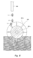
- FIG. 8 is a diagram of the water wheel and its surroundings under a condition in which the amount of liquid reaches a predetermined amount
- FIG. 9 is an overall view of a toner tank in accordance with a second preferred embodiment of the present invention.
- FIG. 10 is a view of a diagram illustrating a second rotation detection mechanism of the toner tank of the second embodiment.
- FIG. 11 is a view of a block diagram illustrating a second control unit of the toner tank of the second embodiment.
- an image forming device of the present invention will be hereinafter described with reference to the attached figures. Note that the position, the size, and so on of the members in the figures may be exaggerated for an easy-to-understand explanation. Also, in the following embodiments, a printer is exemplified as an example of the image forming device of the present invention. However, the present invention is not limited to this. Specifically, the image forming device of the present invention may be a so-called multi-function peripheral (MFP) having functions of a copier and a facsimile, or an image forming device only having a function of a copier. A specific configuration of these members to be described, and other members, may be changed as necessary.
- MFP multi-function peripheral
- FIG. 1 illustrates a color printer 1 as an image forming device according to the first preferred embodiment of the present invention.
- the image forming device 1 includes an image forming section 2 , a paper storing section 3 , a second transfer section 4 , a fixing section 5 , a paper conveyer section 6 , and a discharging section 7 .
- the image forming section 2 is a tandem type image forming section to form a toner image based on image data.
- the paper storing section 3 stores a single or plurality of sheet(s) of paper, which is an example of recording medium.
- the second transfer section 4 transfers the toner image formed by the image forming section 2 onto a sheet of paper.
- the fixing section 5 fixes the toner image transferred onto the sheet of paper.
- the paper conveyor section 6 conveys a sheet of paper stored in the paper storing section 3 to the discharging section 7 .
- the discharging section 7 discharges the sheet of paper onto which the toner image is completely fixed.
- the image forming section 2 includes an intermediate transfer belt 21 , a cleaning unit 22 , and a plurality of image forming units FB, FY, FC, and FM.
- the intermediate transfer belt 21 is preferably a conductive and endless shaped (i.e., looped) member. As indicated by arrows illustrated in FIGS. 1 and 2 , the intermediate transfer belt 21 is circularly driven in the clockwise direction.
- the width of the intermediate transfer belt 21 is greater than the maximum width of a sheet of paper that is allowed to be used in the color printer 1 .
- the term “width” means length that is perpendicular to a direction in which a sheet of paper is conveyed.
- one of the surfaces of the intermediate transfer belt 21 which faces outward, is hereinafter referred to as “front surface,” i.e. an outer peripheral surface, and the other surface thereof is referred to as “back surface,” i.e., an inner peripheral surface.
- the intermediate transfer belt 21 is stretched by a driving roller 41 , a driven roller 23 , and a tension roller 24 .
- the driving roller 41 rotates in accordance with the driving of a driving motor (not illustrated in the figure)
- the intermediate transfer belt 21 is accordingly driven.
- the driven roller 23 and the tension roller 24 are rotated in accordance with the rotation of the intermediate transfer belt 21 .
- the tension roller 24 is a member that applies appropriate tension to the intermediate transfer belt 21 for the purpose of preventing the intermediate transfer belt 21 from being loosened.
- the cleaning unit 22 performs cleaning of the intermediate transfer belt 21 .
- the cleaning unit 22 includes a cleaning roller 22 a and a cleaning blade 22 b.
- the image forming units FB, FY, FC, and FM are disposed to be aligned in the vicinity of the intermediate transfer belt 21 , and are also disposed between the second transfer section 4 and the cleaning unit 22 to clean the intermediate transfer belt 21 .
- the image forming units FB, FY, FC, and FM respectively correspond to colors of black (Bk), yellow (Y), cyan (C), and magenta (M). Note that the arrangement of the image forming units FB, FY, FC, and FM is not necessarily limited to the above. However, the arrangement pattern described above is preferable in consideration of the impact of mixture of the colors on an image to be completed.
- liquid developer circulation devices LB, LY, LC, and LM, toner tanks TB, TY, TC, and TM, and a main carrier tank MT are provided to correspond respectively to the image forming units FB, FY, FC, and FM. Accordingly, the liquid developers of the colors, respectively, are configured to be supplied and recovered. Note that the liquid developer circulation devices LB, LY, LC, and LM will be described in detail in later sections.
- each of the image forming units FB, FY, FC, and FM includes a photosensitive drum 10 , an electric charging device 11 , an exposing device 12 , a developing device 14 , a first transfer roller 20 , a cleaning device 26 , a neutralizing device 13 , and a carrier liquid removal roller 30 .
- the carrier liquid removal roller 30 is not provided in the image forming unit FB that is disposed in a position closest to the second transfer section 4 .
- the configuration of the image forming unit FB is preferably the same as the configurations of the other image forming units excluding this point.
- the photosensitive drum 10 is a columnar member, and is configured to bear an electrically-charged toner image (i.e., positively-charged toner image in the present embodiment) on the surface thereof. As indicated by a dotted arrow illustrated in FIG. 2 , the photosensitive drum 10 is a member that is configured to rotate in the counter-clockwise direction.
- the electric charging device 11 is configured to charge uniformly the surface of the photosensitive drum 10 to have a predetermined polarity and electric potential.
- the exposing device 12 includes a light source (e.g., LED), and emits light onto the surface of the uniformly-charged photosensitive drum 10 in response to the image data to be inputted from an external machine. Accordingly, electric charges are removed from the exposed portion, and an electrostatic latent image is formed on the surface of the photosensitive drum 10 .
- a light source e.g., LED
- the developing device 14 holds the liquid developer including toner and carrier liquid so that the liquid developer is opposed to the electrostatic latent image formed on the surface of the photosensitive drum 10 , and accordingly toner attaches to the electrostatic latent image. Consequently, the electrostatic latent image is developed as the toner image.
- the developing device 14 includes a developing container 140 , a developing roller 141 , a supply roller 142 , a support roller 143 , a supply roller blade 144 , a developing cleaning blade 145 , a developer recovery device 146 , and a developing roller electric charger 147 .
- the developing container 140 is a container that receives a supply of liquid developer that is made up of toner and carrier liquid.
- the liquid developer is supplied to the interior of the developing container 140 through a supply nozzle 278 , while the ratio of the toner with respect to the carrier liquid is preliminarily regulated. This will be described in detail in the following sections. Note that the liquid developer is supplied toward a part of the support roller 143 which is in the vicinity of a nip between the supply roller 142 and the support roller 143 . The residual supplied liquid developer drops below the support roller 143 and is stored at the bottom of the developing container 140 . The stored liquid developer is recovered by the liquid developer circulation devices via a channel R 2 .
- the support roller 143 is disposed approximately in or in the center of the developing container 140 , and makes contact with the supply roller 142 from beneath. Thus a nip is formed between the support roller 143 and the supply roller 142 .
- the supply roller 142 is disposed in a position obliquely upward from the support roller 143 . More specifically, the supply roller 142 is disposed in a position remote from a position immediately above the support roller 143 in a direction away from the supply nozzle 278 .
- a groove is formed on the surface of the supply roller 142 to hold the liquid developer.
- the support roller 143 preferably rotates in the counter-clockwise direction, and the supply roller 142 preferably rotates in the clockwise direction.
- the liquid developer to be supplied from the supply nozzle 278 is temporarily accumulated on the upstream side of the nip in the rotational direction of both rollers 142 and 143 , and is then carried upward while held in the groove formed on the supply roller 142 in accordance with rotations of the rollers 142 and 143 .
- the supply roller blade 144 is press-contacted with the surface of the supply roller 142 , and restricts the amount of the liquid developer to be held by the supply roller 142 to a predetermined amount.
- the residual liquid developer scraped away by the supply roller blade 144 is accumulated on the bottom of the developing container 140 .
- the accumulated liquid developer is recovered by the liquid developer circulation devices via the channel R 2 .
- the developing roller 141 is disposed in an opening formed on the top of the developing container 140 so as to make contact with the supply roller 142 .
- the developing roller 141 is preferably rotated in the same direction as the supply roller 142 .
- the surface of the developing roller 141 moves in the opposite direction from the surface of the supply roller 142 . Accordingly, the liquid developer held on the surface of the supply roller 142 is transferred to the surface of the developing roller 141 .
- thickness of the liquid developer layer formed on the supply roller 142 is restricted to a predetermined value. Therefore, thickness of the liquid developer layer formed on the surface of the developing roller 141 is also maintained at a predetermined value.
- the developing roller electric charger 147 moves the toner included in the liquid developer layer held on the developing roller 141 to the surface side of the developing roller 141 by applying an electric field having the same polarity as that of the charged toner. Accordingly, the developing efficiency is enhanced.
- the developing roller electric charger 147 is disposed to be opposed to the surface of the developing roller 141 on the downstream side in a rotational direction of a contact portion between the developing roller 141 and the supply roller 142 , and on the upstream side of a contact portion between the developing roller 141 and the photosensitive drum 10 .
- the developing roller 141 makes contact with the photosensitive drum 10 , and toner is attached to a portion of the electrostatic latent image on the surface of the photosensitive drum 10 , from which electric charges are removed by the exposing device 12 , by the electric potential difference between the electric potential of the electrostatic latent image on the surface of the photosensitive drum 10 and a developing bias to be applied to the developing roller 141 . Accordingly, a toner image in accordance with the image data is formed on the surface of the photosensitive drum 10 (developing operation).
- the developing cleaning blade 145 is disposed to make contact with the surface of the developing roller 141 on the downstream side of a contact portion between the developing roller 141 and the photosensitive drum 10 in a rotational direction of the developing roller 141 , and on the upstream side of a contact portion between the developing roller 141 and the supply roller 142 in the rotational direction of the developing roller 141 .
- the developing cleaning blade 145 removes the liquid developer on the surface of the developing roller 141 that completed a developing operation with respect to the photosensitive drum 10 .
- the developer recovery device 146 recovers liquid developer removed by the developing cleaning blade 145 , and pumps the liquid developer to a channel R 1 of the liquid developer circulation devices.
- the liquid developer flows down along the surface of the developing cleaning blade 145 .
- the developer recovery device 146 is provided with delivery rollers 34 and 35 to deliver complementarily the liquid developer because of high viscosity of the liquid developer.
- the first transfer roller 20 is disposed to make contact with the back surface of the intermediate transfer belt 21 so as to be opposed to the photosensitive drum 10 .
- Voltage having the opposite polarity from the toner included in the toner image i.e., the polarity is “negative” in the present embodiment
- the first transfer roller 20 applies voltage having the opposite polarity from the toner to the intermediate transfer belt 21 in a position that the first transfer roller 20 makes contact with the intermediate transfer belt 21 .
- the intermediate transfer belt 21 has conductivity, and accordingly, the toner is attracted to the surface side of the intermediate transfer belt 21 and its periphery by the applied voltage.
- the cleaning device 26 is a device that removes the liquid developer left on the photosensitive drum 10 without being transferred to the intermediate transfer belt 21 , and includes a cleaning blade 262 and a conveyer screw 261 .
- the cleaning blade 262 is a member that scrapes away the liquid developer left on the surface of the photosensitive drum 10 , and is also a plate shaped member that is formed to extend in a direction of the rotation shaft of the photosensitive drum 10 . An end portion of the cleaning blade 262 slidingly makes contact with the surface of the photosensitive drum 10 , and scrapes away the liquid developer left on the photosensitive drum 10 in accordance with the rotation of the photosensitive drum 10 .
- the conveyer screw 261 is disposed in the interior of the cleaning device 26 .
- the conveyer screw 261 conveys the liquid developer, which is scraped way by the cleaning blade 262 and is contained in the cleaning device 26 , to the outside of the cleaning device 26 .
- the conveyer screw 261 also conveys the carrier liquid, which is removed from the intermediate transfer belt 21 by a carrier liquid removal roller 30 to be described and is then contained in the interior of the cleaning device 26 , to the outside of the cleaning device 26 .
- the neutralizing device 13 includes a light source that removes electric charges, and removes electric charges from the surface of the photosensitive drum 10 by way of light emitted from the light source. After the liquid developer is removed from the surface of the photosensitive drum 10 by the cleaning blade 262 , the neutralizing device 13 performs removal of electric charges for the next image formation.
- the carrier liquid removal roller 30 is an approximately columnar member that is rotatable around a rotation shaft parallel to a rotation shaft of the photosensitive drum 10 .
- the carrier liquid removal roller 30 rotates in the same direction as the photosensitive drum 10 .
- the carrier liquid removal roller 30 is a member that removes the carrier liquid from the surface of the intermediate transfer belt 21 , and is disposed in a position close to the side that the second transfer section 4 is disposed compared to a position in which the photosensitive drum 10 makes contact with the intermediate transfer belt 21 .
- the carrier liquid removed by the carrier liquid removal roller 30 is stored in the interior of the cleaning device 26 .
- the paper storing section 3 is a section that stores a single or plurality of sheet(s) of paper onto which a toner image is to be fixed, and is disposed at the bottom of the color printer 1 .
- the paper storing section 3 includes a paper feeding cassette 31 in which a single or plurality of sheet(s) of paper is stored, a paper feeding roller 32 , and a pair of separation rollers 33 .
- the second transfer section 4 is a section that transfers the toner image formed on the intermediate transfer belt 21 onto a sheet of paper.
- the second transfer section 4 makes up a transfer device that transfers the toner image onto a sheet of paper together with the above described first transfer roller 20 .
- the second transfer section 4 includes a driving roller 41 that drives the intermediate transfer belt 21 , and a second transfer roller 42 .
- the second transfer roller 42 is pressed toward the driving roller 41 while the intermediate transfer belt 21 is interposed between the second transfer roller 42 and the driving roller 41 .
- the fixing section 5 is a section that fixes the toner image onto a sheet of paper, and is disposed above the second transfer section 4 .
- the fixing section 5 includes a heating roller 51 and a pressing roller 52 .
- the pressing roller 52 is disposed to be opposed to the heating roller 51 , and presses the heating roller 51 .
- the paper conveyer section 6 includes a plurality of pairs of conveyer rollers 74 and a pair of resist rollers 75 .
- the paper conveyer section 6 conveys a sheet of paper from the paper storing section 3 to the second transfer section 4 , the fixing section 5 , and the discharging section 7 .
- other pairs of conveyer rollers are also preferably disposed to be aligned in a direction perpendicular to the diagram illustrated in FIG. 1 , and illustration of the rollers is omitted in the figure.
- the discharging section 7 is a section from which a sheet of paper, on which the toner image is transferred and fixed, is discharged.
- the discharging section 7 includes a plurality of pairs of discharging rollers 71 and a discharging tray 72 that is provided on the top of the color printer 1 . Note that only single pair of discharging rollers 71 is illustrated in FIG. 1 . However, other pairs of discharging rollers are also preferably disposed to be aligned in a direction perpendicular to the diagram illustrated in FIG. 1 , and illustration of the rollers is omitted in the figure.
- FIG. 3 illustrates a schematic view of the entire configuration of the liquid developer circulation device LY.
- the liquid developer circulation device LY is a device that recycles the liquid developer by the circulation of the liquid developer.
- a structure of the liquid developer circulation device LY is hereinafter explained.
- the structures of the other liquid developer circulation devices LB, LC, and LM have the same or similar structure as that of the structure of the liquid developer circulation device LY. Thus, explanation of these structures will be omitted.
- the following types of liquid developer is circulated by the liquid developer circulation device LY: the developer that is scraped away from the surface of the developing roller 141 by the developing cleaning blade 145 ; the developer that is not supplied from the supply roller 142 to the developing roller 141 ; the developer that is supplied to the support roller 143 through the supply nozzle 278 but is left as surplus developer; and the developer that is scraped away from the photosensitive drum 10 by the cleaning device 26 .
- the liquid developer circulation device LY includes a residual developer tank 271 , a developer storing container 272 (liquid storing container), a liquid-amount detection device 28 (see FIG. 4 ), a solid-concentration detection device 273 , a carrier tank CY, a toner tank TY, a reserve tank 277 , a supply nozzle 278 , a recovery container 279 , a separation and extraction device 82 , and a plurality of pumps P 1 -P 10 .
- the residual developer tank 271 is connected to the developing device 14 by the channel R 1 .
- the residual developer tank 271 is a tank that is configured to store the developer scraped away from the surface of the developing roller 141 by the developing cleaning blade 145 .
- the residual developer tank 271 also store the developer collected via the channel R 2 .
- the pump P 1 is attached to the intermediate portion of the channel R 1 .
- the pump P 1 moves the liquid developer scraped away from the surface of the developing roller 141 to the residual developer tank 271 .
- the residual developer tank 271 is connected to the bottom of the developing device 14 by the channel R 2 , and the pump P 5 is attached to the channel R 2 .
- the pump P 5 delivers the liquid developer from the developing container 140 to the residual developer tank 271 .
- the developer storing container 272 is connected to the residual developer tank 271 , and is a member that prepares the developer (i.e., regulating the toner concentration) to be supplied to the developing device 14 .
- the developer storing container 272 is connected to the residual developer tank 271 by the channel R 3 , and the pump P 2 is attached to the channel R 3 .
- the pump P 2 delivers the liquid developer from the residual developer tank 271 to the developer storing container 272 .
- the liquid-amount detection device 28 (liquid-level detection device) illustrated in FIG. 4 is disposed in the interior of the developer storing container 272 , and is configured to detect whether or not the liquid level of the liquid developer stored in the developer storing container 272 reaches a predetermined position.
- a configuration of the liquid-amount detection device 28 will be hereinafter explained in detail.
- the solid-concentration detection device 273 is a device that detects concentration of the toner included in the liquid developer stored in the developer storing container 272 , and is connected to an annular channel R 4 that is connected to the developer storing container 272 .
- the pump P 4 is attached to the upstream side of the solid-concentration detection device 273 in the annular channel R 4 .
- the pump P 4 circulates the liquid developer in the channel R 4 .
- the carrier tank CY stores carrier liquid.
- the carrier liquid is used to reduce concentration of the toner stored in the developer storing container 272 .
- the carrier tank CY is connected to the developer storing container 272 by the channel R 5 to which the pump 3 is attached.
- the pump P 3 delivers the carrier liquid from the carrier tank CY to the developer storing container 272 .
- a separate carrier tank just like the carrier tank CY, is preferably provided in each of the other liquid developer circulation devices LB, LC, and LM, respectively. These carrier tanks receive supply of the carrier liquid from the main carrier tank MT (see FIG. 1 ) that is shared by all the carrier tanks.
- the carrier tanks and the main carrier tank MT are connected by branched pipes (not illustrated in the figure), and each of the branched pipes is exclusively used by each of all the carrier tanks.
- a pump (not illustrated in the figure) is attached to each of the branched pipes.
- the toner tank TY stores the liquid developer, the toner concentration of which is higher than that of the liquid developer to be used in the developing device 14 .
- the liquid developer is used to increase the toner concentration in the developer storing container 272 .
- the toner tank TY is connected to the developer storing container 272 by the channel R 6 to which the pump P 8 is attached.
- the pump P 8 delivers the above described liquid developer from the toner tank TY to the developer storing container 272 .
- the reserve tank 277 is configured to store the liquid developer to be supplied to the developing device 14 .
- the reserve tank 277 is connected to the developer storing container 272 by the channel R 7 to which the pump P 6 is attached.
- the pump P 6 delivers the liquid developer from the developer storing container 272 to the reserve tank 277 .
- the reserve tank 277 is connected to the supply nozzle 278 by the channel R 8 to which the pump P 7 is attached.
- the pump P 7 delivers the liquid developer from the reserve tank 277 to the supply nozzle 278 .
- the supply nozzle 278 is a device that supplies the liquid developer to the developing device 14 .
- the recovery container 279 is a container that temporarily accumulates the liquid developer that is removed from the photosensitive drum 10 by the cleaning device 26 .
- the separation and extraction device 82 is a device that separates the liquid developer into the toner and the carrier liquid and extracts the toner and the carrier liquid separately.
- the separation and extraction device 82 is connected to the recovery container 279 by the channel R 9 .
- the pump P 9 is attached to the channel R 9 , and the pump P 9 delivers the liquid developer accumulated in the recovery container 279 to the separation and extraction device 82 .
- the separation and extraction device 82 separates the liquid developer to be conveyed from the recovery container 279 into the toner and the carrier liquid, and extracts the toner and the carrier liquid.
- the separation and extraction device 82 is connected to the carrier tank CY by the channel R 10 .
- the pump P 10 is attached to the channel R 10 , and the pump P 10 delivers the carrier liquid separated from the liquid developer by the separation and extraction device 82 to the carrier tank CY.
- FIG. 4 illustrates an overall configuration of the liquid-amount detection device 28 .
- the liquid-amount detection device 28 includes a first water wheel 281 (i.e., rotator), a liquid supply port 290 (i.e., liquid supply part), a first rotation detection mechanism 282 , and a first control unit 283 (see FIG. 6 ).
- the first water wheel 281 is disposed in the interior of the developer storing container 272 , and is configured to be rotated by the liquid developer supplied from the liquid supply port 290 when the liquid level of the liquid developer does not reach a predetermined height position.
- the first water wheel 281 is attached to the developer storing container 272 at a predetermined height position, and includes a first rotary shaft 281 a and a first blade member 281 b .
- the predetermined height position is a height position that the bottom portion of the first water wheel 281 equals the liquid level of the liquid developer when the liquid developer is fully stored.
- a condition that the liquid developer is fully stored means a condition in which the supply of the liquid developer from liquid supply port 290 is required to be stopped.
- the first rotary shaft 281 a is rotatably attached to a wall of the developer storing container 272 through a bearing 281 c , and is disposed to penetrate through the wall of the developer storing container 272 .
- the first blade member 281 b is a member that rotates the first rotary shaft 281 a , and is disposed in a first end 281 d of the first rotary shaft 281 a so as to extend radially from the first rotary shaft 281 a .
- the first blade member 281 b is disposed in the interior of the developer storing container 272 , and is disposed in a position where the liquid developer (see reference numeral “L 1 ” in FIG.
- the liquid supply port 290 is provided on an upper portion of the developer storing container 272 , and is connected to the channel R 3 (see FIG. 3 ) to which the pump 2 is attached.
- a liquid developer outlet 272 a is formed on a bottom portion of the developer storing container 272 , and is configured to discharge the liquid developer toward the reserve tank 277 through the channel R 7 to which the pump P 6 is attached (see FIG. 3 ).
- FIG. 5 illustrates an overall configuration of the first rotation detection mechanism 282 .
- the first rotation detection mechanism 282 is a member that is configured to detect rotation of the first water wheel 281 , and includes a first disk 282 a , a first light-emitting member 282 b , and a first light-receiving member 282 c .
- the first disk 282 a is provided in a second end 281 e of the first rotary shaft 281 a .
- Two slits 282 d are formed in the first disk 282 a so as to extend in a radial direction of the first disk 282 a .
- the first light-emitting member 282 b is a member that is configured to emit light toward the first disk 282 a , and includes a LED, for instance.
- the first light-receiving member 282 c is a member that is configured to receive light emitted by the first light-emitting member 282 b .
- the first light-receiving member 282 c is disposed to be opposed to the first light-emitting member 282 b while the first disk 282 a is interposed between the first light-emitting member 282 b and the first light-receiving member 282 c .
- first light-emitting member 282 b and the first light-receiving member 282 c are disposed so that a virtual line connecting the first light-emitting member 282 b and the first light-receiving member 282 c is positioned to be perpendicular to the surface of the first disk 282 a . Furthermore, the first light-emitting member 282 b and the first light-receiving member 282 c are provided so that the virtual line connecting the first light-emitting member 282 b and the first light-receiving member 282 c crosses the slits 282 d when the first disk 282 a rotates.
- the first control unit 283 is a unit that controls the pumps, the first light-emitting member 282 b , the first light-receiving member 282 c , and the like.
- the first control unit 283 is connected to the pumps, the first light-emitting member 282 b , and the first light-receiving member 282 c .
- the first control unit 283 includes first liquid-level detection device 283 a and first supply control device 283 b .
- the first liquid-level detection device 283 a detects whether the liquid level of the liquid developer is positioned in a predetermined position by the light received by the first light-receiving member 282 c .
- the first supply control device 283 b stops supply of the liquid developer from the liquid supply port 290 when the first liquid-level detection device 283 a detects that the liquid level is positioned in a predetermined position.
- the liquid level of the liquid developer does not reach a predetermined position when the first light-receiving member 282 c is capable of intermittently receiving light emitted by the first light-emitting member 282 b during rotation of the first disk 282 a .
- the liquid level of the liquid developer reaches a predetermined position when the first light-receiving member 282 c is not capable of receiving light emitted by the first light-emitting member 282 b or is capable of continuously receiving light for a predetermined period of time or more.
- the period of time is set to about 0.5 second.
- the liquid developer when the liquid developer is supplied from the liquid supply port 290 to the developer storing container 272 , the liquid developer drips and hits the first blade member 281 b . Accordingly, the rotation moment to rotate the first rotary shaft 281 a is applied to the first blade member 281 b .
- the first rotary shaft 281 a rotates and accordingly the first disk 282 a is rotated. Due to this, light emitted by the first light-emitting member 282 b intermittently passes through the slits 282 d , and is received by the first light-receiving member 282 c .
- the first blade member 281 b is soaked in the liquid developer stored in the developer storing container 272 . Accordingly, even when the liquid developer hits the first blade member 281 b , the first blade member 281 b does not move because of resistance applied to the first blade member 281 b by the liquid developer. Consequently, the first rotary shaft 281 a does not rotate and accordingly the first disk 282 a does not rotate. Due to this, the state of the first disk 282 a is not changed.
- the first light-emitting member 282 b when light emitted by the first light-emitting member 282 b is not capable of passing through the slits 282 d , the light is not continuously received by the first light-receiving member 282 c for a predetermined period of time or more.
- the first light-receiving member 282 c when light emitted by the first light-emitting member 282 b passes through the slits 282 d , the light is continuously received by the first light-receiving member 282 c for a predetermined period of time or more. Then, a signal for indicating completion of detection of the liquid level is transmitted from the first liquid-level detection device 283 a to the first supply control device 283 b .
- the first supply control device 283 b stops pump P 2 (see FIG. 3 )
- the pump P 2 is deactivated, and supply of the liquid developer from the liquid supply port 290 , that is, supply of the liquid developer from the residual developer tank 271 is stopped.
- the color printer 1 receives an instruction to form an image from a personal computer (not illustrated in the figure) that is connected to the color printer 1 , the color printer 1 forms toner images of variety of colors, which correspond to the received data of the image formation instruction, with the image forming units FB, FY, FC, and FM. Specifically, electrostatic latent images are formed on the surface of the photosensitive drums 10 based on the image data, and toner is supplied to the electrostatic latent images from the developing device 14 . The toner images that are thus created by the image forming units FB, FY, FC, and FM are transferred to the intermediate transfer belt 21 , and are overlapped with each other on the intermediate transfer belt 21 . Accordingly, a color toner image is formed.
- a sheet of paper which is stored in the paper feeder cassette 31 of the paper storing section 3 , is taken out of the paper feeder cassette 31 by the paper feeder roller 32 , and a sheet of paper is delivered to the paper conveyer section 6 by the pair of separation rollers 33 on a one-by-one basis.
- the sheet of paper is delivered to the pair of resist rollers 75 by a plurality of pairs of conveyer rollers 74 of the paper conveyer section 6 .
- the posture of the sheet of paper is corrected and is temporarily stopped moving by the pair of resist rollers 75 .
- the sheet of paper is delivered into the second transfer section 4 from the pair of resist rollers 75 in synchronization with the timing of the first transfer to the intermediate transfer belt 21 , and the second transfer of the color toner image on the intermediate transfer belt 21 is performed with respect to the sheet of paper by the second transfer section 4 .
- the sheet of paper onto which the color toner image is transferred is delivered to the fixing section 5 , and the color toner image is fixed onto the sheet of paper by the actions of heat and pressure.
- the sheet of paper onto which the color toner image is fixed is further delivered to the discharging section 7 , and is discharged to the discharging tray 72 that is provided in the outside of the color printer 1 by a plurality of pairs of discharging rollers 71 .
- the liquid developer left on the intermediate transfer belt 21 is removed by the cleaning roller 22 a and the cleaning blade 22 b of the cleaning section 22 .
- the liquid developer left on the developing roller 141 without being supplied to the photosensitive drum 10 during the image forming operation is scraped away by the developing cleaning blade 145 , and is delivered to the residual developer tank 271 via the channel R 1 by the action of the pump P 1 .
- the liquid developer received by the developing container 140 is also delivered to the residual developer tank 271 via the channel R 2 by the action of the pump P 5 .
- the liquid developer is supplied to the developer storing container 272 from the residual developer tank 271 via the channel R 3 by the action of the pump P 2 .
- the liquid developer left on the photosensitive drum 10 without being transferred to the intermediate transfer belt 21 is scraped away by the cleaning blade 262 and is stored in the recovery container 279 .
- the liquid developer recovered in the recovery container 279 is conveyed to the separation and extraction device 82 via the channel R 9 by the action of the pump P 9 . Then, a separation and extraction processing of toner and carrier liquid from the liquid developer is performed by the separation and extraction device 82 .
- the carrier liquid extracted by the separation and extraction device 82 is delivered to the carrier tank CY via the channel R 10 by the action of the pump P 10 .
- concentration of toner included in the liquid developer stored in the developer storing container 272 is detected by the solid-concentration detection device 273 , and concentration regulation of the liquid developer in the developer storing container 272 is performed.
- concentration of toner included in the liquid developer stored in the developer storing container 272 is detected by the solid-concentration detection device 273 , and concentration regulation of the liquid developer in the developer storing container 272 is performed.
- the carrier liquid is supplied to the developer storing container 272 from the carrier tank CY via channel R 5 by the action of the pump P 3 .
- the toner concentration is lower than a predetermined criterion range
- the liquid developer, the toner concentration of which is higher than that of the liquid developer to be used in the developing device 14 is supplied from the toner tank TY to the developer storing container 272 via the channel R 6 by the action of the pump P 8 .
- the liquid developer for which concentration regulation is performed is supplied from the developer storing container 272 to the reserve tank 277 via the channel R 7 by the action of the pump P 6 as necessary. Then, the liquid developer stored in the reserve tank 277 is delivered to the supply nozzle 278 via the channel R 8 by the action of the pump P 7 , and is then supplied to the developing device 14 from the supply nozzle 278 .
- the liquid developer left on the developing roller 141 without being supplied to the photosensitive drum 10 during the image formation operation is scraped away by the developing cleaning blade 145 , and is then delivered to the residual developer tank 271 via the channel R 1 . Then, when the amount of the liquid developer in the developer storing container 272 is used up, the residual developer is supplied from the residual developer tank 271 to the developer storing container 272 .
- the pump P 2 is driven by the first control unit 283 , and the liquid developer in the residual developer tank 271 is supplied to the developer storing container 272 via the channel R 3 .
- the liquid developer is supplied from the liquid supply port 290 that is connected to the channel R 3 so as to hit the first blade member 281 b .
- the first rotary shaft 281 a is rotated until the liquid level of the liquid developer reaches a predetermined position (see FIG. 7 ). Then, light emitted by the first light-emitting member 282 b is intermittently received by the first light-receiving member 282 c in accordance with the rotation.
- the first rotary shaft 281 a stops rotating (see FIG. 8 ).
- the first water wheel 281 stops rotating under the condition that light emitted by the first light-emitting member 282 b is not capable of passing through the slits 282 d , and light emitted by the first light-emitting member 282 b is not continuously received by the first light-receiving member 282 c for a predetermined period of time or more.
- the first water wheel 281 stops rotating under the condition that light emitted by the first light-emitting member 282 b is capable of passing through the slits 282 d , light emitted by the first light-emitting member 282 b is received by the first light-receiving member 282 c for a predetermined period of time or more.
- the first supply control device 283 b decides that the first light-receiving member 282 c continuously receive or does not receive light for a predetermined period of time or more
- the first supply control device 283 b deactivates the pump P 2 , and thus stops supply of the liquid developer from the liquid supply port 290 .
- developer in the developer storing container 272 is stirred all the time by a stirring member (not shown) in the developer storing container 272 .
- concentration of the toner included in the liquid developer stored in the developer storing container 272 is detected by the solid-concentration detection device 273 .
- the carrier liquid is supplied to the developer storing container 272 from the carrier tank CY.
- the toner concentration is lower than a predetermined criterion range in the developer storing container 272 , the liquid developer with high toner concentration is supplied to the developer storing container 272 from the toner tank TY.
- the regulated liquid developer stored in the developer storing container 272 is supplied to the reserve tank 277 as necessary.
- the liquid developer stored in the reserve tank 277 is supplied to the developing device 14 through the supply nozzle 278 as necessary.
- FIG. 9 illustrates a configuration of the toner tank TY (liquid containing device) to which a second preferred embodiment of the present invention is applied.
- the toner tank TY is configured to store the liquid developer, the toner concentration of which is higher than that of the liquid developer to be used in the developing device 14 , in the interior thereof, and is configured to supply the liquid developer to the developing device 14 (see FIG. 3 ).
- the toner tank TY includes a toner tank main body 61 (i.e., liquid storing container), an outlet 62 , a liquid supply device 63 , a second water wheel 64 (i.e., rotator), a second rotation detection mechanism 65 , and a second control unit 66 (see FIG. 11 ).
- the second water wheel 64 , the second rotation detection mechanism 65 , and the second control unit 66 make up a second liquid-level detection device 67 .
- the second liquid-level detection device 67 is a device that detects that the liquid developer in the toner tank TY is consumed and accordingly the liquid level of the liquid developer becomes lower than a predetermined height. In other words, detection of the liquid level of the liquid developer is performed to inform a user that the amount of the liquid developer in the toner tank TY is reduced to be less than a predetermined amount and exchange of the toner tank TY is necessary.
- the toner tank main body 61 is a container having a space in the interior thereof, and the space is configured to store the liquid developer.
- the cross-section of the toner tank main body 61 which is perpendicular to the figure, is formed in a rectangular shape.
- the outlet 62 is a part that supplies the liquid developer stored in the toner tank main body 61 to the developer storing container 272 .
- the outlet 62 is disposed in a bottom portion of the toner tank main body 61 .
- the liquid supply device 63 is a device that supplies the liquid developer to the interior of the toner tank main body 61 .
- the liquid supply device 63 includes a liquid supply port 631 (i.e., liquid supply part), a liquid suction port 632 (i.e., liquid outlet), a tube 633 (i.e., liquid channel), and a pump 634 .
- the liquid supply port 631 is attached to an upper surface of the toner tank main body 61 , and is a part that supplies the liquid developer toward the second water wheel 64 .
- the liquid suction port 632 is disposed in a bottom portion of the toner tank main body 61 , and is a part that suctions the liquid developer stored in the bottom part of the toner tank main body 61 .
- the tube 633 is a part that connects the liquid suction port 632 and the liquid supply port 631 .
- the pump 634 is preferably disposed in the intermediate part of the tube 633 , and is a member that performs a series of action of suctioning the liquid developer through the liquid suction port 632 , pumping the suctioned liquid developer to the liquid supply port 631 , and supplying the pumped liquid developer toward the second water wheel 64 .
- the second water wheel 64 is disposed in the interior of the toner tank main body 61 , and is a member that is configured to be rotated by the liquid developer when the liquid level of the liquid developer is lower than a predetermined height.
- the second water wheel 64 is attached to the toner tank main body 61 at a predetermined height position, and includes a second rotary shaft 641 a and a second blade member 641 b .
- the predetermined height position is the height position of the bottom portion of the second blade member 641 b , which corresponds to the liquid level of the liquid developer having the amount for which exchange of the toner tank TY is set to be performed.
- the second rotary shaft 641 a is rotatably attached to a wall of the toner tank main body 61 through a bearing 641 c , and is disposed to penetrate through the wall of the toner tank main body 61 .
- the second blade member 641 b is a member that rotates the second rotary shaft 641 a , and is provided in an end of the second rotary shaft 641 a so as to extend radially from the second rotary shaft 641 a .
- the second blade member 641 b is disposed in the interior of the toner tank main body 61 , and is disposed in a position where the liquid developer (see reference numeral “L 2 ” in FIG. 9 ) to be supplied from the liquid supply port 631 hits the second blade member 641 b.
- the second rotation detection mechanism 65 is a mechanism that detects rotation of the second water wheel 64 , and includes a second disk 651 , a second light-emitting member 652 , and a second light-receiving member 653 .
- the second disk 651 is disposed on the other end of the second rotary shaft 641 a , and includes reflection portions 651 a that are capable of reflecting light emitted by the second light-emitting member 652 , and non-reflection portions 651 b that are not capable of reflecting light.
- Each of the reflection portions 651 a and the non-reflection portions 651 b is formed in a shape obtained by dividing the second disk 651 into quarter sections in the circumferential direction.
- the reflection portions 651 a and the non-reflection portions 651 b are alternately disposed in the circumferential direction of the second disk 651 .
- the second light-emitting member 652 is a member that is configured to emit light toward the second disk 651 , and includes a LED.
- the second light-receiving member 653 is a member that is configured to receive light emitted by the second light-emitting member 652 .
- the second light-receiving member 653 is disposed to be capable of receiving reflected light, that is, light that is emitted by the second light-emitting member 652 and is then reflected by the reflection portions 651 a.
- the second control unit 66 is a unit that controls the pump 634 , the second light-emitting member 652 .
- the second control unit 66 is connected to the pump 634 , the second light-emitting member 652 , the second light-receiving member 653 , and the like.
- the second control unit 66 includes a second liquid-level detection device 66 a and a second supply control device 66 b .
- the second liquid-level detection device 66 a detects whether the liquid level of the liquid developer is positioned in a predetermined position by the light received by the second light-receiving member 653 .
- the second supply control device 66 b stops supply of the liquid developer from the liquid supply port 631 when the second liquid-level detection device 66 a detects that the liquid level of the liquid developer is positioned in a predetermined position.
- the liquid level of the liquid developer is lower than a predetermined position when the second light-receiving member 653 is capable of intermittently receiving light emitted by the second light-emitting member 652 during the rotation of the second disk 651 .
- the liquid level of the liquid developer is higher than or equal to predetermined height when the second light-receiving member 653 is not capable of continuously receiving light emitted by the second light-emitting member 652 for a predetermined period of time or more, or is capable of continuously receiving light emitted by the second light-emitting member 652 for a predetermined period of time or more.
- the second rotary shaft 641 a is not allowed to be rotated by the liquid developer supplied from the liquid supply port 631 under the condition that the liquid level of the liquid developer is higher than or equal to a predetermined height and at least a part of the second blade member 641 b is positioned in the liquid developer. Accordingly, light emitted by the second light-emitting member 652 is not continuously received by the second light-receiving member 653 for a predetermined period of time or more under the condition that rotation of the second water wheel 64 is stopped while the non-reflection portion 651 b is irradiated by the second light-emitting member 652 .
- the reflection portion 651 a is intermittently irradiated by the second light-emitting member 652 and accordingly light emitted by the second light-emitting member 652 is intermittently received by the second light-receiving member 653 . It is detected that the liquid level of the liquid developer reaches a predetermined height position by the rotation of the second water wheel 64 .
- FIGS. 9-11 An operation to detect a remaining amount of liquid developer stored in the toner tank TY will be hereinafter explained with reference to FIGS. 9-11 .
- the interior of the toner tank TY is filled with the liquid developer.
- the liquid developer is suctioned from the liquid suction port 632 , and is supplied to the interior of the toner tank TY through the liquid supply port 631 .
- the interior of the toner tank TY is filled with the liquid developer. Accordingly, even when the liquid developer supplied through the liquid supply port 631 hits the second blade member 641 b , the second water wheel 64 does not rotate.
- the high-concentration developer is required for regulating the toner concentration of the liquid developer stored in the developer storing container 272 . Accordingly, the toner stored in the toner tank TY is supplied to the developer storing container 272 . Accordingly, the liquid developer stored in the toner tank TY is gradually reduced. Then, if the amount of the liquid developer reaches a predetermined amount (i.e., the amount for which exchange of the toner tank TY is required), the second rotary shaft 641 a is rotated when the liquid developer supplied from the liquid supply port 631 hits the second blade member 641 b .
- a predetermined amount i.e., the amount for which exchange of the toner tank TY is required
- the second light-emitting member 652 When the second disk 651 is rotated in accordance with the rotation of the second rotary shaft 641 a , the second light-emitting member 652 alternately irradiates the reflection portion 651 a and the non-reflection portion 651 b , and the second light-receiving member 653 intermittently receives light emitted by the second light-emitting member 652 .
- the second light-receiving member 653 When light emitted by the second light-emitting member 652 is intermittently received by the second light-receiving member 653 , it is judged that the amount of liquid developer in the toner tank TY has reached a predetermined amount. Then, an instruction to exchange the toner tank TY is displayed on a display unit (not illustrated in the figure) of the image forming device.
- a color printer is exemplified.
- the present invention is not limited to this, and may be applied to a photocopier, a MFP, and the like.
- the liquid-level detection device of the present invention may be provided not only in the developer storing container 272 and the toner tank TY but also in the interior of the other liquid storing container.
- the liquid-level detection device may be provided in the interior of the reserve tank 277 and the carrier tank CY of the above described first embodiment.
- the liquid-level detection device of the present invention is useful for detecting not only the liquid level of the liquid developer but also that of the other type of liquid, and may be provided in the interior of the liquid storing container that is configured to be included in devices excluding the image forming device.
- the first rotation detection mechanism 282 is used.
- the second rotation detection mechanism 65 may be used in the first embodiment.
- the first rotation detection mechanism 282 may be used in the above described second embodiment.
- the liquid level of the liquid developer and the like reaches a predetermined height based on whether or not rotation of the first water wheel 281 and that of the second water wheel 64 are stopped.
- the liquid level of the liquid developer and the like may be configured to be detected by detecting the change of the rotation speed.
- detection of the liquid level may be configured to be performed by driving the pump 634 only for a predetermined period of time after the liquid developer is supplied to the developer storing container 272 .
- the second light-emitting member 652 may be caused to emit light only under the above situation.
- the reflection portion 651 a and the non-reflection portion 651 b are used.
- a high-reflection portion and a low-reflection portion may be provided instead of the reflection portion 651 a and the non-reflection portion 651 b .
- the high-reflection portion is a portion having light reflectance higher than that of the low-reflection portion.
- the low-reflection portion is a portion having light reflectance lower than that of the high-reflection portion.
- the second light-receiving member 653 receives light, intensity of which is alternately changed to be strong and weak.
- the second light-receiving member 653 receives high-intensity constant light or low-intensity constant light.
- Emission of light by a light-emitting member may be configured to be performed for a specified period of time at predetermined intervals without being continuously performed.
- the term “configured” as used herein to describe a component, section or part of a device includes hardware and/or software that is constructed and/or programmed to carry out the desired function.
- the term “comprising” and its derivatives, as used herein are intended to be open ended terms that specify the presence of the stated features, elements, components, groups, integers, and/or steps, but do not exclude the presence of other unstated features, elements, components, groups, integers and/or steps.
- the foregoing also applied to words having similar meanings such as the terms, “including,” “having,” and their derivatives.
- the term “part,” “section,” “portion,” “member,” or “element” when used in the singular can have the dual meaning of a single part or a plurality of parts.
- terms of degree such as “substantially,” “about,” and “approximately” as used herein mean a reasonable amount of deviation of the modified term such that the end result is not significantly changed. For example, these terms can be construed as including a deviation of at least ⁇ 5% of the modified term if this deviation would not negate the meaning of the word it modifies.
Landscapes
- Physics & Mathematics (AREA)
- General Physics & Mathematics (AREA)
- Thermal Sciences (AREA)
- Fluid Mechanics (AREA)
- Wet Developing In Electrophotography (AREA)
- Measurement Of Levels Of Liquids Or Fluent Solid Materials (AREA)
Abstract
Description
Claims (13)
Applications Claiming Priority (2)
| Application Number | Priority Date | Filing Date | Title |
|---|---|---|---|
| JP2007-141618 | 2007-05-29 | ||
| JP2007141618A JP4324624B2 (en) | 2007-05-29 | 2007-05-29 | Liquid level detector |
Publications (2)
| Publication Number | Publication Date |
|---|---|
| US20080298843A1 US20080298843A1 (en) | 2008-12-04 |
| US8301043B2 true US8301043B2 (en) | 2012-10-30 |
Family
ID=40088363
Family Applications (1)
| Application Number | Title | Priority Date | Filing Date |
|---|---|---|---|
| US12/124,866 Expired - Fee Related US8301043B2 (en) | 2007-05-29 | 2008-05-21 | Liquid-level detection device, image forming device, and liquid containing device |
Country Status (2)
| Country | Link |
|---|---|
| US (1) | US8301043B2 (en) |
| JP (1) | JP4324624B2 (en) |
Cited By (1)
| Publication number | Priority date | Publication date | Assignee | Title |
|---|---|---|---|---|
| US11433684B2 (en) | 2018-08-22 | 2022-09-06 | Hewlett-Packard Development Company, L.P. | Print apparatuses using reusable print agent containers |
Families Citing this family (7)
| Publication number | Priority date | Publication date | Assignee | Title |
|---|---|---|---|---|
| US8958722B2 (en) * | 2009-10-28 | 2015-02-17 | Kyocera Mita Corporation | Extractor for extracting a dispersoid and a dispersion medium and imaging forming apparatus employing this extractor |
| JP5493771B2 (en) * | 2009-11-26 | 2014-05-14 | コニカミノルタ株式会社 | Paper post-processing apparatus and image forming system |
| JP5617447B2 (en) * | 2010-08-31 | 2014-11-05 | 富士ゼロックス株式会社 | Image forming apparatus and belt conveying apparatus |
| US8604934B2 (en) * | 2010-09-20 | 2013-12-10 | Texas Lfp, Llc | System and method for optically detecting low liquid level condition |
| JP5620591B2 (en) * | 2011-01-31 | 2014-11-05 | ヒューレット−パッカード デベロップメント カンパニー エル.ピー.Hewlett‐Packard Development Company, L.P. | Printing system using ink with high solids content |
| JP2016177000A (en) * | 2015-03-18 | 2016-10-06 | 富士ゼロックス株式会社 | Development device and image formation apparatus |
| EP4550056A1 (en) * | 2023-11-06 | 2025-05-07 | Zhuhai Pantum Electronics Co., Ltd. | Developer supply control device and image forming device |
Citations (10)
| Publication number | Priority date | Publication date | Assignee | Title |
|---|---|---|---|---|
| JPS59126570A (en) | 1983-01-10 | 1984-07-21 | Ricoh Co Ltd | Developer detector of wet developing device |
| JPS59197820A (en) * | 1983-04-25 | 1984-11-09 | Mitsubishi Electric Corp | Rotary encoder |
| JPH08254440A (en) * | 1995-03-17 | 1996-10-01 | Olympus Optical Co Ltd | Optical encoder |
| JPH09126865A (en) | 1995-11-01 | 1997-05-16 | Ricoh Co Ltd | Liquid level detector |
| JPH11148851A (en) | 1997-05-12 | 1999-06-02 | Denso Corp | Refueling fuel measuring device, fuel remaining amount measuring device, and evaporated fuel processing device |
| JPH11174814A (en) * | 1997-12-08 | 1999-07-02 | Canon Inc | Developer remaining amount detecting device, developing device, image forming device, and process cartridge |
| JP2000146639A (en) | 1998-11-12 | 2000-05-26 | Tokyo Electron Ltd | Flow meter and fluid supply device |
| JP2005077402A (en) | 2003-09-01 | 2005-03-24 | Nobuo Kiyono | Flow sensor and flow rate measuring device |
| JP2006170788A (en) * | 2004-12-15 | 2006-06-29 | Canon Inc | Optical encoder |
| JP2006313322A (en) * | 2005-04-06 | 2006-11-16 | Pentax Corp | Developer container |
-
2007
- 2007-05-29 JP JP2007141618A patent/JP4324624B2/en not_active Expired - Fee Related
-
2008
- 2008-05-21 US US12/124,866 patent/US8301043B2/en not_active Expired - Fee Related
Patent Citations (11)
| Publication number | Priority date | Publication date | Assignee | Title |
|---|---|---|---|---|
| JPS59126570A (en) | 1983-01-10 | 1984-07-21 | Ricoh Co Ltd | Developer detector of wet developing device |
| JPS59197820A (en) * | 1983-04-25 | 1984-11-09 | Mitsubishi Electric Corp | Rotary encoder |
| JPH08254440A (en) * | 1995-03-17 | 1996-10-01 | Olympus Optical Co Ltd | Optical encoder |
| JPH09126865A (en) | 1995-11-01 | 1997-05-16 | Ricoh Co Ltd | Liquid level detector |
| JPH11148851A (en) | 1997-05-12 | 1999-06-02 | Denso Corp | Refueling fuel measuring device, fuel remaining amount measuring device, and evaporated fuel processing device |
| US6230558B1 (en) | 1997-05-12 | 2001-05-15 | Denso Corporation | Apparatus and method for measuring fuel flow rate and residual fuel quantity and for controlling evaporated fuel |
| JPH11174814A (en) * | 1997-12-08 | 1999-07-02 | Canon Inc | Developer remaining amount detecting device, developing device, image forming device, and process cartridge |
| JP2000146639A (en) | 1998-11-12 | 2000-05-26 | Tokyo Electron Ltd | Flow meter and fluid supply device |
| JP2005077402A (en) | 2003-09-01 | 2005-03-24 | Nobuo Kiyono | Flow sensor and flow rate measuring device |
| JP2006170788A (en) * | 2004-12-15 | 2006-06-29 | Canon Inc | Optical encoder |
| JP2006313322A (en) * | 2005-04-06 | 2006-11-16 | Pentax Corp | Developer container |
Non-Patent Citations (1)
| Title |
|---|
| Yanajima (JP 2006-313322 A, Nov. 2006) JPO Machine Translation, Nov. 2006. * |
Cited By (1)
| Publication number | Priority date | Publication date | Assignee | Title |
|---|---|---|---|---|
| US11433684B2 (en) | 2018-08-22 | 2022-09-06 | Hewlett-Packard Development Company, L.P. | Print apparatuses using reusable print agent containers |
Also Published As
| Publication number | Publication date |
|---|---|
| JP2008298444A (en) | 2008-12-11 |
| US20080298843A1 (en) | 2008-12-04 |
| JP4324624B2 (en) | 2009-09-02 |
Similar Documents
| Publication | Publication Date | Title |
|---|---|---|
| US8301043B2 (en) | Liquid-level detection device, image forming device, and liquid containing device | |
| JP2009069417A (en) | Image forming apparatus | |
| AU2015300524B2 (en) | Powder container and image forming apparatus | |
| US9785086B2 (en) | Developer container, developing device, process cartridge, and image forming apparatus | |
| JP2007011004A (en) | Image forming apparatus | |
| US8948658B2 (en) | Developing device and image forming apparatus | |
| CN101071286A (en) | Developing apparatus, image forming apparatus and density detection method | |
| US10281839B2 (en) | Image forming apparatus and developer supply device with first and second transport members configured to transport developer at different speeds | |
| US8452214B2 (en) | Developing apparatus and image forming apparatus | |
| US10007212B2 (en) | Developing apparatus having developer guiding portions | |
| US9280094B1 (en) | Trim bar entry geometry for a dual component development electrophotographic image forming device | |
| JP5958801B2 (en) | Developing device and image forming apparatus | |
| JP4991488B2 (en) | Image forming apparatus | |
| JP5158473B2 (en) | Developing device and image forming apparatus | |
| US20130230341A1 (en) | Developing device and image-forming apparatus | |
| JP4852286B2 (en) | Developing device and image forming apparatus | |
| JP4841530B2 (en) | Liquid level detection device, mixed liquid supply system, and image forming apparatus | |
| JP7765737B2 (en) | Toner container and image forming apparatus | |
| US9291947B1 (en) | Sealing ribs for a developer unit of a dual component development electrophotographic image forming device | |
| US8923733B2 (en) | Developer supplying device and image forming apparatus | |
| JP5026097B2 (en) | Image forming apparatus | |
| JP5352984B2 (en) | Developer container, developer supply device, and image forming apparatus | |
| US8000637B2 (en) | Supplying and discharging developer in an image forming apparatus, process cartridge and developing device | |
| JP6814387B2 (en) | Cleaning equipment, process cartridges, and image forming equipment | |
| US20220334513A1 (en) | Image forming apparatus |
Legal Events
| Date | Code | Title | Description |
|---|---|---|---|
| AS | Assignment |
Owner name: KYOCERA MITA CORPORATION, JAPAN Free format text: ASSIGNMENT OF ASSIGNORS INTEREST;ASSIGNORS:HOBO, JUMPEI;MURASE, KOJI;UEDA, HIROYUKI;AND OTHERS;REEL/FRAME:020980/0686;SIGNING DATES FROM 20080520 TO 20080521 Owner name: KYOCERA MITA CORPORATION, JAPAN Free format text: ASSIGNMENT OF ASSIGNORS INTEREST;ASSIGNORS:HOBO, JUMPEI;MURASE, KOJI;UEDA, HIROYUKI;AND OTHERS;SIGNING DATES FROM 20080520 TO 20080521;REEL/FRAME:020980/0686 |
|
| AS | Assignment |
Owner name: KYOCERA DOCUMENT SOLUTIONS INC., JAPAN Free format text: CHANGE OF NAME;ASSIGNOR:KYOCERA MITA CORPORATION;REEL/FRAME:028206/0137 Effective date: 20120401 |
|
| ZAAA | Notice of allowance and fees due |
Free format text: ORIGINAL CODE: NOA |
|
| ZAAB | Notice of allowance mailed |
Free format text: ORIGINAL CODE: MN/=. |
|
| STCF | Information on status: patent grant |
Free format text: PATENTED CASE |
|
| FEPP | Fee payment procedure |
Free format text: PAYOR NUMBER ASSIGNED (ORIGINAL EVENT CODE: ASPN); ENTITY STATUS OF PATENT OWNER: LARGE ENTITY |
|
| FPAY | Fee payment |
Year of fee payment: 4 |
|
| MAFP | Maintenance fee payment |
Free format text: PAYMENT OF MAINTENANCE FEE, 8TH YEAR, LARGE ENTITY (ORIGINAL EVENT CODE: M1552); ENTITY STATUS OF PATENT OWNER: LARGE ENTITY Year of fee payment: 8 |
|
| FEPP | Fee payment procedure |
Free format text: MAINTENANCE FEE REMINDER MAILED (ORIGINAL EVENT CODE: REM.); ENTITY STATUS OF PATENT OWNER: LARGE ENTITY |
|
| LAPS | Lapse for failure to pay maintenance fees |
Free format text: PATENT EXPIRED FOR FAILURE TO PAY MAINTENANCE FEES (ORIGINAL EVENT CODE: EXP.); ENTITY STATUS OF PATENT OWNER: LARGE ENTITY |
|
| STCH | Information on status: patent discontinuation |
Free format text: PATENT EXPIRED DUE TO NONPAYMENT OF MAINTENANCE FEES UNDER 37 CFR 1.362 |
|
| FP | Lapsed due to failure to pay maintenance fee |
Effective date: 20241030 |