US8604934B2 - System and method for optically detecting low liquid level condition - Google Patents
System and method for optically detecting low liquid level condition Download PDFInfo
- Publication number
- US8604934B2 US8604934B2 US12/886,381 US88638110A US8604934B2 US 8604934 B2 US8604934 B2 US 8604934B2 US 88638110 A US88638110 A US 88638110A US 8604934 B2 US8604934 B2 US 8604934B2
- Authority
- US
- United States
- Prior art keywords
- liquid level
- reflective
- tank
- disk
- reflective layer
- Prior art date
- Legal status (The legal status is an assumption and is not a legal conclusion. Google has not performed a legal analysis and makes no representation as to the accuracy of the status listed.)
- Active, expires
Links
Images


Classifications
-
- G—PHYSICS
- G01—MEASURING; TESTING
- G01F—MEASURING VOLUME, VOLUME FLOW, MASS FLOW OR LIQUID LEVEL; METERING BY VOLUME
- G01F23/00—Indicating or measuring liquid level or level of fluent solid material, e.g. indicating in terms of volume or indicating by means of an alarm
- G01F23/30—Indicating or measuring liquid level or level of fluent solid material, e.g. indicating in terms of volume or indicating by means of an alarm by floats
- G01F23/32—Indicating or measuring liquid level or level of fluent solid material, e.g. indicating in terms of volume or indicating by means of an alarm by floats using rotatable arms or other pivotable transmission elements
- G01F23/36—Indicating or measuring liquid level or level of fluent solid material, e.g. indicating in terms of volume or indicating by means of an alarm by floats using rotatable arms or other pivotable transmission elements using electrically actuated indicating means
- G01F23/366—Indicating or measuring liquid level or level of fluent solid material, e.g. indicating in terms of volume or indicating by means of an alarm by floats using rotatable arms or other pivotable transmission elements using electrically actuated indicating means using optoelectrically actuated indicating means
-
- G—PHYSICS
- G01—MEASURING; TESTING
- G01F—MEASURING VOLUME, VOLUME FLOW, MASS FLOW OR LIQUID LEVEL; METERING BY VOLUME
- G01F23/00—Indicating or measuring liquid level or level of fluent solid material, e.g. indicating in terms of volume or indicating by means of an alarm
- G01F23/30—Indicating or measuring liquid level or level of fluent solid material, e.g. indicating in terms of volume or indicating by means of an alarm by floats
- G01F23/32—Indicating or measuring liquid level or level of fluent solid material, e.g. indicating in terms of volume or indicating by means of an alarm by floats using rotatable arms or other pivotable transmission elements
- G01F23/34—Indicating or measuring liquid level or level of fluent solid material, e.g. indicating in terms of volume or indicating by means of an alarm by floats using rotatable arms or other pivotable transmission elements using mechanically actuated indicating means
Definitions
- This invention relates to indicating devices for displaying liquid level condition within a tank or other container, and more particularly to a system and method for optically determining and remotely signaling a low liquid level condition within a tank.
- Conventional forklifts typically include a vehicle frame, a mast attached to the front end of the vehicle frame, a fork carriage adapted for elevational movement along the mast to raise and lower loads, and a counterweight located at the rear end of the vehicle frame for retaining balance of the forklift as heavyweight loads are lifted.
- An engine is typically mounted at the center of the vehicle frame and usually is covered with a hood.
- a driver's seat is typically fixedly secured to the hood and surrounded by an overhead guard which defines a cabin.
- Many such forklifts are powered by liquid propane and therefore include a liquid propane tank that is removably mounted for the purpose of refueling on a support structure of the counterweight.
- the propane tank In order to prevent forklift down time or the chance of fuel outage at a location remote from the replacement tank, the propane tank is often replaced before it is completely empty. Since some tanks do not have a fuel gauge, a significant amount of cost can be incurred since useful amounts of propane may be left in the tank upon replacement. Even if a fuel sight gauge is provided, the dial indicator is not readily viewable by an operator.
- Such gauges employ a magnetically driven dial for physically viewing the liquid level as well as a magnetic flux field sensor mounted on the dial for monitoring a position of the dial and generating an electric signal indicative of liquid level within the tank.
- a magnetically driven dial for physically viewing the liquid level as well as a magnetic flux field sensor mounted on the dial for monitoring a position of the dial and generating an electric signal indicative of liquid level within the tank.
- Such a device is disclosed in U.S. Pat. No. 6,564,632 issued to Herbert G. Ross, Jr. on May 20, 2003.
- this device can provide the operator a means for remotely viewing the liquid level condition within the tank without leaving the operating position, it can become damaged if precautions are not observed. For example, if the magnetic flux field sensor is not removed from the gauge head before the tank is exchanged, the sensor, transmission cable and/or dial can become damaged and thus prevent transmission of the liquid level condition to the remote position.
- a system for remotely determining a liquid level condition within a tank includes a liquid level gauge connectable to the tank, a dial assembly associated with the liquid level gauge and an optical transceiver for determining a reflectivity of the dial assembly.
- the gauge includes a float, a shaft operably connected to the float with the shaft being rotatable upon movement of the float in response to a change in liquid level within the tank, and a driving magnet connected to the shaft for rotation therewith.
- the dial assembly includes a reflective layer, a blocking layer positioned over the reflective layer for blocking at least a portion of the reflective layer, and a disk having a driven magnet that is magnetically coupled to the driving magnet such that rotation of the shaft causes rotation of the disk.
- One of the reflective and blocking layers is associated with the disk for rotation therewith.
- the optical transceiver is positioned for projecting radiant energy toward the reflective layer and detecting the presence or absence of reflected radiant energy and for generating a signal indicative of low liquid level within the tank when at least a substantial portion of the reflective layer is covered by the blocking layer.
- a method of determining a low liquid level condition within a tank includes providing a liquid level gauge with an indicator dial, determining a reflectivity of the dial, and generating a low level warning signal when at least one of the following conditions occurs: a) the reflectivity is below a predetermined level, and b) a malfunction occurs during the determining step.
- FIG. 1 is an isometric view of a system for remotely determining a liquid level condition within a tank associated with a forklift or other vehicle;
- FIG. 2 is a sectional view of the system taken along line 2 - 2 of FIG. 1 ;
- FIG. 3 is a top isometric view of a dial assembly in accordance with the present invention connected to a gauge head;
- FIG. 4 is an enlarged sectional view of the dial assembly taken along line 4 - 4 of FIG. 3 ;
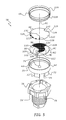
- FIG. 5 is a top isometric exploded view of the dial assembly and gauge head
- FIG. 6 is a bottom isometric exploded view of the dial assembly
- FIG. 7 is a top plan view of the dial assembly with a dial in a first position indicative of an empty tank condition
- FIG. 8 is a top plan view of the dial assembly with the dial in a second position denoting a near-empty tank condition
- FIG. 9 is a top plan view of the dial assembly with the dial in a third position denoting a half-full tank condition
- FIG. 10 is a top plan view of the dial assembly with the dial in a fourth position indicative of a full tank condition.
- FIG. 11 is a top isometric view of a dial assembly in accordance with a further embodiment of the invention.
- the container 12 represents a propane tank or LP gas cylinder removably connected to a vehicle 14 , such as a gas-powered forklift or the like.
- the gas-powered forklift 14 is of conventional construction and accordingly is only partially shown in FIG. 1 .
- the forklift 14 includes a counterweight 18 located at the rear end of a vehicle frame 20 for retaining balance of the forklift as heavyweight loads are lifted.
- An engine (not shown) is typically mounted at the center of the vehicle frame and usually is covered with a hood 22 .
- a driver's seat 24 is typically fixedly secured to the hood 22 and is surrounded by an overhead guard (not shown) supported by rear upright members or columns 26 and front upright members (not shown) to define a protective cabin for the operator.
- the forklift 14 is powered by liquid propane and therefore includes the tank 12 which is removably mounted on support structure 30 ( FIG. 2 ) of the counterweight and held in place by a pair of securing straps 31 .
- the tank 12 is also of conventional construction and includes a pressure cylinder 32 for holding a quantity of propane, an annular base 34 located at one end of the cylinder 32 for orienting the cylinder in an upright position during storage, and an annular wall or valve guard 36 located at the opposite end of the cylinder 32 .
- the tank 12 may include other components typically associated with a propane cylinder, such as a fill/supply valve, over-pressure safety valve, and so on.
- An alignment pin 35 extends from the counterweight 18 of the forklift and through an alignment slot or opening 37 to properly orient the tank on the forklift.
- the present invention is not only applicable to propane tanks and forklifts, but may apply to other vehicles and/or stationary equipment as well as other containers where it is desirous to remotely determine a liquid level condition.
- the system 10 of the present invention preferably includes a liquid level gauge 38 mounted to and extending through an end wall 40 of the tank 12 in a well-known manner, a dial assembly 58 connected to the gauge 38 , an optical transceiver 42 connected to the forklift 14 for sensing a condition of the dial assembly 58 , and an indicator 44 operably associated with the optical transceiver 42 for remotely indicating the gauge condition to an operator.
- the optical transceiver 42 is preferably connected to one of the rear columns 26 via a bracket 36 or other connecting means, such as adhesives, mechanical fasteners, hook and loop material, and so on.
- liquid level gauge 16 and optical transceiver 18 preferably work in conjunction to detect a predetermined low liquid level condition inside the tank 12 , as will be described in greater detail below.
- the indicator 44 can include any well-known means for visually and/or audibly alerting a person to the tank condition, including but not limited to speakers, warning lights, LED's, LCD or Oled displays, buzzers, chimes, and so on.
- the liquid level gauge 38 has a float 46 connected to a pivot arm 48 which is in turn connected to a gear 50 rotatably mounted on a hollow support tube 52 of the liquid level gauge 38 .
- a spur gear 54 meshes with the gear 50 and causes rotation of a shaft 55 (shown in hidden line) extending through the support tube 52 .
- the shaft in turn rotates a driving magnet 57 (shown in hidden line) within a mounting head 56 of the liquid level gauge 38 .
- the dial assembly 58 is preferably attached to the mounting head 56 and is magnetically driven by the rotating driving magnet 57 to thereby indicate liquid level, as will be described in greater detail below.
- the mounting head 56 is in turn screwed into the end wall 40 of the tank 12 in a conventional manner.
- liquid level gauge 38 Further details of the liquid level gauge 38 can be found in U.S. Pat. No. 6,041,650 issued on Mar. 28, 2000 to Swinder et al., the disclosure of which is hereby incorporated by reference. It will be understood that other types of liquid level gauges can be used without departing from the spirit and scope of the present invention.
- the dial assembly 58 in accordance with a preferred embodiment of the invention, includes a base 60 , a disk 62 mounted on the base for rotation with respect thereto, a lens or cap 64 connected to the base, and a blocking layer 66 connected to the lens 64 .
- the base 60 is preferably circular in construction and includes a bottom wall 68 , a continuous side wall 70 extending upwardly from the bottom wall, locking fingers 72 extending downwardly from the bottom wall 68 , and a conically-shaped pin 74 located at an axial center of the bottom wall and extending upwardly therefrom.
- the locking fingers 72 each include an inwardly extending projection 76 that engages a corresponding slot 78 formed in the mounting head 56 so that the base 60 can be installed on the mounting head 56 in a snap-fit engagement.
- fastening means known in the art such as screws or other fasteners, without departing from the spirit and scope of the invention.
- the disk 62 is preferably in the form of a circular-shaped body 80 with an upper surface 82 and a lower surface 84 .
- a pair of spaced bosses 86 extend downwardly from the lower surface 84 and a driven magnet 88 is located in each boss.
- a center pivot 90 extends downwardly from the lower surface 84 between the bosses 86 and engages the pin 74 of the base 60 so that the disk 62 rotates in both clockwise and counter-clockwise directions about a central axis 92 of the dial assembly 58 with respect to the base. It will be understood that other well-known means for rotatably connecting the disk 62 to the base 60 can be used.
- the driven magnets 88 are magnetically coupled to the driving magnet 57 associated with the shaft 55 of the liquid level gauge 38 and thus serve to cause corresponding rotation of the disk 62 when the float 46 is moved in response to a change in liquid level within the tank 12 .
- the disk has been shown as rotatably connected to the base, the disk can alternatively or additionally be rotatably connected to the lens or other structure without departing from the spirit and scope of the invention.
- a reflective layer 94 is located on the upper surface 82 of the disk 62 and preferably includes a first reflective segment 96 with a first radius 106 and a second reflective segment 100 with a second radius 102 .
- the second radius is greater than the first radius such that the second reflective segment 100 extends from a center of the disk 62 to an edge 104 thereof and the first reflective segment 96 extends to a position spaced from the edge.
- the first reflective segment 96 preferably terminates at a first leading edge 98 and extends peripherally around the disk and terminates at a second leading edge 108 associated with the second reflective segment 100 .
- the first and second leading edges extend at an obtuse angle.
- the second reflective segment 96 also preferably terminates at the second leading edge 108 and extends peripherally around the disk and terminates at a first trailing edge 110 of the second reflective segment 100 .
- the significance of the reflective segments will be described in greater detail below with respect to FIGS. 7-10 .
- the reflective layer 94 is preferably die-cut from a single piece of retro-reflective adhesive tape and applied to the upper surface 82 of the disk 62 .
- a suitable retro-reflective tape such as ScotchliteTM reflective tape by 3M, can include thousands of highly-efficient micro prisms that reflect radiant energy back toward the light source.
- the reflective layer can be formed from other reflective materials such as reflective glass, plastic or metallic materials or coatings, as well as paints or inks that are sprayed, screened or printed onto the disk 62 , without departing from the spirit and scope of the present invention.
- a pointer 112 is also preferably located on the upper surface 82 of the disk 62 and is preferably in alignment with or closely adjacent to the first leading edge 98 of the first reflective segment 96 for visually indicating a liquid level condition in conjunction with blocking layer 66 . Although shown as triangular in shape, it will be understood that the pointer 112 can be of any suitable shape for indicating a liquid level condition. In accordance with a further embodiment of the invention, the pointer 112 can be eliminated and the first leading edge 98 of the first reflective segment 96 can serve as the pointer.
- the lens 64 preferably includes an upper wall 114 and a continuous side wall 116 extending downwardly from the upper wall.
- the lens 64 can be constructed of any suitable transparent or translucent material which allows the observer to view the disk 62 and the blocking layer 66 through the upper wall 114 .
- the side wall 116 preferably engages the side wall 70 of the base 60 when assembled and can be connected together through any well-known means such as adhesive bonding, heat welding, mechanical fastening, mutually engageable threads, friction fit, and so on.
- the blocking layer 66 is preferably printed, screened or otherwise applied onto a lower surface 118 of the upper wall 114 and is therefore fixed against movement with the lens 64 .
- the blocking layer 66 can be formed as a separate element and connected to the lens 64 through any well-known connecting means.
- the blocking layer 66 preferably includes an opaque region 120 with a first transparent section or window 122 and a second transparent section or window 124 located diametrically opposite the first window.
- the first and second windows are preferably formed as cut-outs in the blocking layer.
- the first window 122 is larger than the second window 124 and includes a scale 126 that denotes the liquid level condition within the tank 12 , such as empty, 1 ⁇ 4 tank, 1 ⁇ 2 tank, full, and so on.
- the windows 122 and 124 are preferably formed as transparent sections of the blocking layer 66 .
- the term “transparent” as used herein does not necessarily refer to completely transparent but rather denotes sufficient transparency to allow an observer to visually determine a position of the underlying disk 62 with respect to the opaque region 120 and allow at least some radiant energy from the optical transceiver to traverse the windows.
- the term “opaque” as used herein does not necessarily mean completely opaque but rather denotes a condition where transmission of radiant energy from the optical transceiver is sufficiently impaired to prevent a sufficient quantity or intensity of radiant energy to be reflected back to the transceiver.
- the first window 122 is bordered by a first edge 128 and a second edge 130 of the opaque region 120 that respectively coincide with “empty” and “full” conditions of the tank 12 .
- An angle A ( FIG. 7 ) between the first and second edges 128 , 130 is preferably sufficiently large to create a sufficiently long arc length to expose the pointer 112 and at least a portion of the first reflective segment 96 between the empty and full tank conditions ( FIGS. 7-10 ) as denoted by the scale 126 when the disk 62 is rotated in response to movement of the float 46 ( FIG. 2 ).
- the second window 124 is bordered by a third edge 132 and a fourth edge 134 of the opaque region 120 that extend at an angle B to create a sufficiently long arc length so that at least a portion of the second reflective segment 100 is exposed during rotation of the disk 62 between the empty and full tank conditions.
- the angle A is approximately 100 degrees while the angle B is approximately 24 degrees for a particular liquid level gauge having a predefined angular rotation of the driving magnet 57 ( FIG. 2 ) of approximately 100 degrees when the float 46 is moved in response to a change in liquid level within the tank 12 between empty and full tank positions.
- angles for the window edges, the arc lengths of the reflective segments and the amount of angular rotation of the disk 62 , as well as the arc length and contents of the scale 126 can greatly vary and will depend at least in part on the particular liquid level gauge used and/or the type and amount of information related to liquid level to be displayed for visual observation and/or electronic detection.
- the optical transceiver 42 preferably includes a transmitter 136 that emits radiant energy in the electromagnetic spectrum and a receiver 138 that detects the emitted radiant energy.
- the transmitter 136 comprises a LED that emits radiant energy in the near-infrared region of the electromagnetic spectrum and the receiver comprises a photosensor, such as a photodiode or phototransistor, that detects radiant energy in the near-infrared region.
- the transmitter and/or receiver can alternatively emit and receive radiant energy in the ultraviolet, visible and/or infrared light spectrums without departing from the spirit and scope of the present invention.
- the transmitter 136 and receiver 138 are preferably located within a housing 140 which is in turn connected to the mounting bracket 46 .
- the housing may also include circuitry (not shown) for detecting when a predetermined condition has occurred and transmitting a signal via an electrical cable 142 to the indicator 44 to inform an operator of the predetermined condition.
- the predetermined condition is a low liquid level condition of the tank 12 based on a predetermined reflected value detected by the receiver.
- the electrical cable 142 can also supply electrical power to the optical transceiver 42 from the forklift 14 or other power source.
- the optical transceiver 42 can be battery-powered and a signal can be sent to the indicator 44 via a wireless signal in a well-known manner.
- the transmitter 136 emits light toward the dial assembly 58 , as represented by phantom lines 144 .
- the emitted light is then reflected toward the emitter 138 , as shown by dashed lines 146 , when at least a portion of one or more of the reflective regions 96 , 100 ( FIG. 5 ) is exposed through the blocking layer 66 .
- Suitable and well-known techniques for reducing ambient noise can be employed, including but not limited to polarizing the light output, providing one or more light filters, generating a predetermined pattern of light pulses that is recognized by the receiver and related circuitry, and so on.
- the reflective segments and opaque region are arranged to indicate a low level condition with sufficient contents in the tank to allow the forklift (or other vehicle) to return to the refueling station.
- the signal will still be sent to the indicator 44 .
- a visual inspection of the dial assembly 58 will immediately inform an operator that a system malfunction has occurred when the pointer 112 is not aligned with an empty or near-empty condition, i.e. when the contents of the tank are sufficient to preclude a low level warning.
- This fail-safe mode of operation ensures, with a high level of confidence, that the system 10 is operating correctly when the indicator 44 does not receive a signal.
- the low level signal may be sporadic due to fuel sloshing. Accordingly, well-known damping or delay techniques can be used for mechanically and/or electronically stabilizing the signal.
- one of the windows can be eliminated where sufficient reflection is generated with a single window. It will be further understood that one or more of the windows can be enlarged or reduced in size to reveal more or less of the reflective area. In addition, more windows and/or reflective segments can be provided without departing from the spirit and scope of the present invention.
- a dial assembly 150 in accordance with a further embodiment of the invention is illustrated.
- the dial assembly 150 is similar in construction to the dial assembly 58 previously described, with the exception that the reflective layer 94 is preferably located on an upper surface 152 of the bottom wall 68 of the base 60 and the blocking layer 66 is located on the disk 62 A.
- the disk 62 A is formed of a transparent material and the blocking layer 66 is an opaque layer on the transparent material to form transparent windows 122 A and 124 A.
- the disk 62 A is formed of an opaque material and the windows 122 A and 122 B are formed as cut-outs in the material.
- the reflective layer is fixedly connected to the base 60 and the blocking layer is fixedly connected to the magnetically-coupled disk 62 A for rotation therewith in response to float movement.
- the scale 126 can either be associated with the disk 62 A or with the base 60 in this embodiment and the pointer (not shown) is associated with the other of the disk and base.
- the pointer can be eliminated and the leading edge 98 of the first reflective section 96 can function as the pointer for visually observing the liquid level condition within the tank.
- the leading edge 128 of the blocking layer 66 can serve as the pointer.
Abstract
Description
Claims (19)
Priority Applications (1)
| Application Number | Priority Date | Filing Date | Title |
|---|---|---|---|
| US12/886,381 US8604934B2 (en) | 2010-09-20 | 2010-09-20 | System and method for optically detecting low liquid level condition |
Applications Claiming Priority (1)
| Application Number | Priority Date | Filing Date | Title |
|---|---|---|---|
| US12/886,381 US8604934B2 (en) | 2010-09-20 | 2010-09-20 | System and method for optically detecting low liquid level condition |
Publications (2)
| Publication Number | Publication Date |
|---|---|
| US20120068849A1 US20120068849A1 (en) | 2012-03-22 |
| US8604934B2 true US8604934B2 (en) | 2013-12-10 |
Family
ID=45817243
Family Applications (1)
| Application Number | Title | Priority Date | Filing Date |
|---|---|---|---|
| US12/886,381 Active 2032-01-07 US8604934B2 (en) | 2010-09-20 | 2010-09-20 | System and method for optically detecting low liquid level condition |
Country Status (1)
| Country | Link |
|---|---|
| US (1) | US8604934B2 (en) |
Cited By (5)
| Publication number | Priority date | Publication date | Assignee | Title |
|---|---|---|---|---|
| US20170259093A1 (en) * | 2015-08-13 | 2017-09-14 | Choon Lye Tan | A fire extinguisher with checking function |
| USD832124S1 (en) | 2018-01-11 | 2018-10-30 | Rochester Gauges, Inc. | Sensor module for liquid level gauge |
| USD833310S1 (en) | 2018-01-11 | 2018-11-13 | Rochester Gauges, Inc. | Lens cover for liquid level gauge |
| US10175088B1 (en) | 2018-01-11 | 2019-01-08 | Rochester Gauges, Inc. | Liquid level gauge with removable indicator assembly |
| US10247589B2 (en) * | 2016-04-21 | 2019-04-02 | KSR IP Holdings, LLC | Fluid level monitor |
Families Citing this family (3)
| Publication number | Priority date | Publication date | Assignee | Title |
|---|---|---|---|---|
| US9170148B2 (en) * | 2011-04-18 | 2015-10-27 | Bradley Fixtures Corporation | Soap dispenser having fluid level sensor |
| NL2010374C2 (en) * | 2013-02-28 | 2014-09-01 | Vehold B V | Liquid level gauge device. |
| ES2827289T3 (en) * | 2017-09-29 | 2021-05-20 | Aiut Sp Z O O | Liquid gas level measurement system |
Citations (15)
| Publication number | Priority date | Publication date | Assignee | Title |
|---|---|---|---|---|
| US4688028A (en) | 1985-12-04 | 1987-08-18 | Conn Sidney H | Audible low-fuel alarm for propane fuel tank |
| US5410913A (en) | 1993-12-15 | 1995-05-02 | Thomas G. Faria Corporation | Remote indicating liquid level sensor |
| US5780711A (en) | 1994-04-06 | 1998-07-14 | Gaslow International Limited | Pressure indicator with relatively movable screen and dial |
| US6023970A (en) * | 1995-08-04 | 2000-02-15 | Blaine; David H. | Disposable electromagnetic fluid sensor |
| US6041650A (en) * | 1997-08-26 | 2000-03-28 | Rochester Gauges, Inc. | Liquid level gauge |
| US6336362B1 (en) | 1998-01-22 | 2002-01-08 | Roy A. Duenas | Method and system for measuring and remotely reporting the liquid level of tanks and the usage thereof |
| US6398382B1 (en) * | 2000-06-12 | 2002-06-04 | Seh America, Inc. | Apparatus and method for indicating liquid level in a chemical tank |
| US6437697B1 (en) | 2001-07-13 | 2002-08-20 | John C. Caro | Propane level monitor assembly |
| US6564632B2 (en) | 2001-01-11 | 2003-05-20 | Rochester Gauges, Inc. | Liquid level gauge with removable hall device |
| US6742396B2 (en) * | 2001-04-07 | 2004-06-01 | Robertshaw Controls Company | Method for upgrading a dial indicator to provide remote indication capability |
| US6822565B2 (en) | 1999-07-20 | 2004-11-23 | Keith A. Thomas | Wireless gauge alert |
| US7219546B2 (en) * | 2005-03-18 | 2007-05-22 | Rochester Gauges, Inc. | Gear and drive shaft assembly for a float gauge |
| US20080298843A1 (en) * | 2007-05-29 | 2008-12-04 | Kyocera Mita Corporation | Liquid-level detection device, image forming device, and liquid containing device |
| US20090058666A1 (en) * | 2007-09-05 | 2009-03-05 | Chris Clabaugh | Tank fluid level monitor and indicator |
| US7652563B2 (en) | 2007-09-13 | 2010-01-26 | Kuryakyn Holdings, Inc. | Optical input device |
-
2010
- 2010-09-20 US US12/886,381 patent/US8604934B2/en active Active
Patent Citations (15)
| Publication number | Priority date | Publication date | Assignee | Title |
|---|---|---|---|---|
| US4688028A (en) | 1985-12-04 | 1987-08-18 | Conn Sidney H | Audible low-fuel alarm for propane fuel tank |
| US5410913A (en) | 1993-12-15 | 1995-05-02 | Thomas G. Faria Corporation | Remote indicating liquid level sensor |
| US5780711A (en) | 1994-04-06 | 1998-07-14 | Gaslow International Limited | Pressure indicator with relatively movable screen and dial |
| US6023970A (en) * | 1995-08-04 | 2000-02-15 | Blaine; David H. | Disposable electromagnetic fluid sensor |
| US6041650A (en) * | 1997-08-26 | 2000-03-28 | Rochester Gauges, Inc. | Liquid level gauge |
| US6336362B1 (en) | 1998-01-22 | 2002-01-08 | Roy A. Duenas | Method and system for measuring and remotely reporting the liquid level of tanks and the usage thereof |
| US6822565B2 (en) | 1999-07-20 | 2004-11-23 | Keith A. Thomas | Wireless gauge alert |
| US6398382B1 (en) * | 2000-06-12 | 2002-06-04 | Seh America, Inc. | Apparatus and method for indicating liquid level in a chemical tank |
| US6564632B2 (en) | 2001-01-11 | 2003-05-20 | Rochester Gauges, Inc. | Liquid level gauge with removable hall device |
| US6742396B2 (en) * | 2001-04-07 | 2004-06-01 | Robertshaw Controls Company | Method for upgrading a dial indicator to provide remote indication capability |
| US6437697B1 (en) | 2001-07-13 | 2002-08-20 | John C. Caro | Propane level monitor assembly |
| US7219546B2 (en) * | 2005-03-18 | 2007-05-22 | Rochester Gauges, Inc. | Gear and drive shaft assembly for a float gauge |
| US20080298843A1 (en) * | 2007-05-29 | 2008-12-04 | Kyocera Mita Corporation | Liquid-level detection device, image forming device, and liquid containing device |
| US20090058666A1 (en) * | 2007-09-05 | 2009-03-05 | Chris Clabaugh | Tank fluid level monitor and indicator |
| US7652563B2 (en) | 2007-09-13 | 2010-01-26 | Kuryakyn Holdings, Inc. | Optical input device |
Cited By (5)
| Publication number | Priority date | Publication date | Assignee | Title |
|---|---|---|---|---|
| US20170259093A1 (en) * | 2015-08-13 | 2017-09-14 | Choon Lye Tan | A fire extinguisher with checking function |
| US10247589B2 (en) * | 2016-04-21 | 2019-04-02 | KSR IP Holdings, LLC | Fluid level monitor |
| USD832124S1 (en) | 2018-01-11 | 2018-10-30 | Rochester Gauges, Inc. | Sensor module for liquid level gauge |
| USD833310S1 (en) | 2018-01-11 | 2018-11-13 | Rochester Gauges, Inc. | Lens cover for liquid level gauge |
| US10175088B1 (en) | 2018-01-11 | 2019-01-08 | Rochester Gauges, Inc. | Liquid level gauge with removable indicator assembly |
Also Published As
| Publication number | Publication date |
|---|---|
| US20120068849A1 (en) | 2012-03-22 |
Similar Documents
| Publication | Publication Date | Title |
|---|---|---|
| US8604934B2 (en) | System and method for optically detecting low liquid level condition | |
| US11860026B2 (en) | Liquid level gauge with integral electronic display | |
| US6679116B2 (en) | Liquid level gauge with removable Hall device | |
| US7256702B2 (en) | Gas supply pressure alarm device | |
| US10082416B1 (en) | Liquid level gauge with integral electronic display | |
| US8179272B2 (en) | Tank fluid level monitor and refill indicator | |
| US10175088B1 (en) | Liquid level gauge with removable indicator assembly | |
| JPH02306124A (en) | Tank level alarm | |
| JP2012532332A (en) | Fluid level transmission device having fluid tank and external signal transmission means | |
| US9304027B2 (en) | Angled gauge head for liquid level sending unit | |
| WO1999040553A1 (en) | Alarm device for sensing gas quantity within pressure vessel | |
| EP2177881B1 (en) | Indicator | |
| US11130669B2 (en) | Fuel delivery spout for avoiding misfuelling and method therefor | |
| US5649450A (en) | Alarm assembly for product level gauge | |
| US20020124643A1 (en) | Flexible optical fiber remote level sensor | |
| JPH08227498A (en) | Head-up display for vehicle and navigation device using same | |
| CA3066583A1 (en) | Liquid level gauge assembly with integral electronic display | |
| KR101260231B1 (en) | Pointer of instrument cluster for vehicle | |
| EP3566028B1 (en) | Liquid level gauge with removable indicator assembly | |
| US6981331B1 (en) | Fork level indicator with magnetic dampening means | |
| WO2021184058A1 (en) | Fluid level gauge apparatus | |
| US3320923A (en) | Liquid level gage | |
| EP1691178A1 (en) | Magnetic rotation detector for use with a liquid level sensor | |
| JPH0633380Y2 (en) | On-site / remote residual amount detector for fluid stored in a portable pressure vessel | |
| JPH0410480Y2 (en) |
Legal Events
| Date | Code | Title | Description |
|---|---|---|---|
| STCF | Information on status: patent grant |
Free format text: PATENTED CASE |
|
| FPAY | Fee payment |
Year of fee payment: 4 |
|
| FEPP | Fee payment procedure |
Free format text: MAINTENANCE FEE REMINDER MAILED (ORIGINAL EVENT CODE: REM.); ENTITY STATUS OF PATENT OWNER: SMALL ENTITY |
|
| AS | Assignment |
Owner name: ROCHESTER GAUGES, LLC, TEXAS Free format text: CHANGE OF NAME;ASSIGNOR:ROCHESTER GAUGES, INC.;REEL/FRAME:057756/0918 Effective date: 20180522 |
|
| AS | Assignment |
Owner name: ROCHESTER GAUGES, INC., TEXAS Free format text: ASSIGNMENT OF ASSIGNORS INTEREST;ASSIGNOR:TEXAS LFP, LLC;REEL/FRAME:057959/0554 Effective date: 20180523 Owner name: TEXAS LFP, LLC, TEXAS Free format text: ASSIGNMENT OF ASSIGNORS INTEREST;ASSIGNOR:ROSS, HERBERT G;REEL/FRAME:057959/0532 Effective date: 20180523 |
|
| FEPP | Fee payment procedure |
Free format text: ENTITY STATUS SET TO UNDISCOUNTED (ORIGINAL EVENT CODE: BIG.); ENTITY STATUS OF PATENT OWNER: LARGE ENTITY |
|
| FEPP | Fee payment procedure |
Free format text: 7.5 YR SURCHARGE - LATE PMT W/IN 6 MO, LARGE ENTITY (ORIGINAL EVENT CODE: M1555); ENTITY STATUS OF PATENT OWNER: LARGE ENTITY |
|
| MAFP | Maintenance fee payment |
Free format text: PAYMENT OF MAINTENANCE FEE, 8TH YEAR, LARGE ENTITY (ORIGINAL EVENT CODE: M1552); ENTITY STATUS OF PATENT OWNER: LARGE ENTITY Year of fee payment: 8 |
|
| AS | Assignment |
Owner name: ROCHESTER SENSORS, LLC, TEXAS Free format text: CHANGE OF NAME;ASSIGNOR:ROCHESTER GAUGES, LLC;REEL/FRAME:060958/0729 Effective date: 20220210 |
|
| AS | Assignment |
Owner name: ALTER DOMUS (US) LLC, ILLINOIS Free format text: SECURITY INTEREST;ASSIGNOR:ROCHESTER SENSORS, LLC;REEL/FRAME:063575/0049 Effective date: 20230508 |