US8257399B2 - Anchoring device for anchoring a rod in bones or vertebrae - Google Patents
Anchoring device for anchoring a rod in bones or vertebrae Download PDFInfo
- Publication number
- US8257399B2 US8257399B2 US12/333,873 US33387308A US8257399B2 US 8257399 B2 US8257399 B2 US 8257399B2 US 33387308 A US33387308 A US 33387308A US 8257399 B2 US8257399 B2 US 8257399B2
- Authority
- US
- United States
- Prior art keywords
- rod
- contact surface
- base
- channel
- head
- Prior art date
- Legal status (The legal status is an assumption and is not a legal conclusion. Google has not performed a legal analysis and makes no representation as to the accuracy of the status listed.)
- Active, expires
Links
- 238000004873 anchoring Methods 0.000 title claims abstract description 73
- 210000000988 bone and bone Anatomy 0.000 title claims abstract description 30
- 239000000560 biocompatible material Substances 0.000 claims description 2
- 238000000034 method Methods 0.000 claims 3
- 238000001356 surgical procedure Methods 0.000 description 4
- 230000004048 modification Effects 0.000 description 3
- 238000012986 modification Methods 0.000 description 3
- 230000006641 stabilisation Effects 0.000 description 3
- 238000011105 stabilization Methods 0.000 description 3
- 230000008901 benefit Effects 0.000 description 2
- 206010039722 scoliosis Diseases 0.000 description 2
- RTAQQCXQSZGOHL-UHFFFAOYSA-N Titanium Chemical compound [Ti] RTAQQCXQSZGOHL-UHFFFAOYSA-N 0.000 description 1
- 229910045601 alloy Inorganic materials 0.000 description 1
- 239000000956 alloy Substances 0.000 description 1
- 238000010276 construction Methods 0.000 description 1
- 230000001747 exhibiting effect Effects 0.000 description 1
- 238000003780 insertion Methods 0.000 description 1
- 230000037431 insertion Effects 0.000 description 1
- 238000004519 manufacturing process Methods 0.000 description 1
- 229910052751 metal Inorganic materials 0.000 description 1
- 239000002184 metal Substances 0.000 description 1
- 229910001092 metal group alloy Inorganic materials 0.000 description 1
- 230000000087 stabilizing effect Effects 0.000 description 1
- 239000010936 titanium Substances 0.000 description 1
- 229910052719 titanium Inorganic materials 0.000 description 1
- 230000007704 transition Effects 0.000 description 1
Images


Classifications
-
- A—HUMAN NECESSITIES
- A61—MEDICAL OR VETERINARY SCIENCE; HYGIENE
- A61B—DIAGNOSIS; SURGERY; IDENTIFICATION
- A61B17/00—Surgical instruments, devices or methods, e.g. tourniquets
- A61B17/56—Surgical instruments or methods for treatment of bones or joints; Devices specially adapted therefor
- A61B17/58—Surgical instruments or methods for treatment of bones or joints; Devices specially adapted therefor for osteosynthesis, e.g. bone plates, screws, setting implements or the like
- A61B17/68—Internal fixation devices, including fasteners and spinal fixators, even if a part thereof projects from the skin
- A61B17/70—Spinal positioners or stabilisers ; Bone stabilisers comprising fluid filler in an implant
- A61B17/7001—Screws or hooks combined with longitudinal elements which do not contact vertebrae
- A61B17/7032—Screws or hooks with U-shaped head or back through which longitudinal rods pass
-
- A—HUMAN NECESSITIES
- A61—MEDICAL OR VETERINARY SCIENCE; HYGIENE
- A61B—DIAGNOSIS; SURGERY; IDENTIFICATION
- A61B17/00—Surgical instruments, devices or methods, e.g. tourniquets
- A61B17/56—Surgical instruments or methods for treatment of bones or joints; Devices specially adapted therefor
- A61B17/58—Surgical instruments or methods for treatment of bones or joints; Devices specially adapted therefor for osteosynthesis, e.g. bone plates, screws, setting implements or the like
- A61B17/68—Internal fixation devices, including fasteners and spinal fixators, even if a part thereof projects from the skin
- A61B17/70—Spinal positioners or stabilisers ; Bone stabilisers comprising fluid filler in an implant
- A61B17/7001—Screws or hooks combined with longitudinal elements which do not contact vertebrae
- A61B17/7035—Screws or hooks, wherein a rod-clamping part and a bone-anchoring part can pivot relative to each other
- A61B17/7037—Screws or hooks, wherein a rod-clamping part and a bone-anchoring part can pivot relative to each other wherein pivoting is blocked when the rod is clamped
-
- A—HUMAN NECESSITIES
- A61—MEDICAL OR VETERINARY SCIENCE; HYGIENE
- A61B—DIAGNOSIS; SURGERY; IDENTIFICATION
- A61B17/00—Surgical instruments, devices or methods, e.g. tourniquets
- A61B17/56—Surgical instruments or methods for treatment of bones or joints; Devices specially adapted therefor
- A61B17/58—Surgical instruments or methods for treatment of bones or joints; Devices specially adapted therefor for osteosynthesis, e.g. bone plates, screws, setting implements or the like
- A61B17/68—Internal fixation devices, including fasteners and spinal fixators, even if a part thereof projects from the skin
- A61B17/84—Fasteners therefor or fasteners being internal fixation devices
- A61B17/86—Pins or screws or threaded wires; nuts therefor
-
- A—HUMAN NECESSITIES
- A61—MEDICAL OR VETERINARY SCIENCE; HYGIENE
- A61B—DIAGNOSIS; SURGERY; IDENTIFICATION
- A61B17/00—Surgical instruments, devices or methods, e.g. tourniquets
- A61B17/56—Surgical instruments or methods for treatment of bones or joints; Devices specially adapted therefor
- A61B17/58—Surgical instruments or methods for treatment of bones or joints; Devices specially adapted therefor for osteosynthesis, e.g. bone plates, screws, setting implements or the like
- A61B17/60—Surgical instruments or methods for treatment of bones or joints; Devices specially adapted therefor for osteosynthesis, e.g. bone plates, screws, setting implements or the like for external osteosynthesis, e.g. distractors, contractors
- A61B2017/603—Surgical instruments or methods for treatment of bones or joints; Devices specially adapted therefor for osteosynthesis, e.g. bone plates, screws, setting implements or the like for external osteosynthesis, e.g. distractors, contractors with three points of contact, e.g. tripod
Definitions
- the invention relates to an anchoring device for anchoring a rod in bones or vertebrae which can be used with at least two rods having a different diameter.
- bone anchoring devices which comprise a shaft to be anchored in the bone and a head to be connected to a rod.
- a rod connects several bone anchoring devices.
- the diameter of the rods ranges from 3 mm to more than 6 mm.
- the diameter of the rod which is used in the lower part of the spine is larger than the diameter of the rod which is used in the upper part of the spine. For example, as shown in FIG.
- Typical bone anchoring devices have a recess for receiving a rod.
- the diameter of the recess may be slightly larger than the diameter of the rod in order to account for small variations in manufacturing tolerances.
- the tolerance may allow rod diameter variation of about 2%. However, the noted tolerance is not sufficient to allow the use of different diameter rods as discussed above for different spinal surgery applications.
- bone anchoring devices such as pedicle screws
- pedicle screws For each diameter of the rod, specific bone anchoring devices, such as pedicle screws, are required. They differ from each other in particular by the size of the recess into which the rod is inserted.
- the provision of having different bone anchoring devices available for surgery increases the costs and renders spinal surgery more complicated for surgeon.
- U.S. Pat. No. 5,873,878 discloses an anchoring member for attachment to a vertebra and for use with a first rod having a first diameter and a second rod having a second, smaller diameter.
- the anchoring member has an insert member which can be inserted into the head of the anchoring member so as to allow the insertion of a rod with a smaller diameter.
- An anchoring device can provide a safe clamping of any of the rods having a different diameter.
- the clamping force does not depend on the diameter of the rod.
- the bone anchoring device is constructed to minimize the number of parts. Hence it does not require additional parts to allow the fixation of different rods.
- the anchoring device can be used in particular for the correction of scoliosis in children.
- the scoliosis correction device When the child grows up, it may be necessary to adapt the scoliosis correction device. For example, it may be necessary to use other rods with a greater diameter as those originally inserted.
- the bone anchoring device according to the invention it is possible to replace the originally used rods in a second surgery with the bone anchors remaining anchored in the vertebrae.
- FIG. 1 shows a schematic view of the spinal column with spinal stabilization devices using rods of different diameter in different regions of the spine.
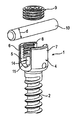
- FIG. 2 shows a perspective exploded view of the anchoring device according to a first embodiment.
- FIG. 3 shows a perspective view of the bone anchoring device of FIG. 2 in an assembled state.
- FIG. 4 shows a sectional view of the anchoring device of FIG. 3 in an assembled state, the section being taken perpendicular to the rod axis.
- FIG. 5 shows a perspective exploded view of the anchoring device according to a second embodiment.
- FIG. 6 shows a perspective view of the anchoring device of FIG. 5 in an assembled state.
- FIG. 7 shows a partial sectional view of the anchoring device of FIG. 6 , the section being taken in a plane perpendicular to rod axis and through the center of the anchoring device.
- FIG. 8 a shows a side view of the pressure element of the anchoring device of FIG. 7 .
- FIG. 8 b shows a sectional view of the pressure element of the anchoring device of FIG. 7 , the section being taken in a plane perpendicular to the rod axis.
- FIG. 8 c shows a top view of the pressure element of the anchoring device of FIG. 7 .
- FIG. 8 d shows a perspective view of the pressure element of the anchoring device of FIG. 7 .
- FIG. 9 a to d shows schematically the clamping of the rod in the pressure element shown in FIGS. 8 a to 8 d ), where different rods having different diameters are used.
- FIG. 10 a to 10 d show schematically the clamping of rods having different diameters in a pressure element of a modified embodiment.
- FIG. 11 a to 11 b show modified embodiments of the seat of the rod.
- the anchoring device 1 includes a shaft 2 with a tip 3 at one end and a head 4 at the other end.
- the shaft has a bone thread in at least a portion thereof.
- the head 4 has on its side opposite to the tip a recess 5 which forms two free legs 6 , 7 are formed defining a channel for receiving a rod 10 .
- An internal thread 8 is provided at the legs 6 , 7 for receiving an inner screw 9 for fixation of the rod 10 in the channel.
- the rod has a circular or substantially circular cross section.
- the recess 5 two opposite and substantially vertical flat side walls 12 , 13 are formed as best seen in FIG. 4 .
- the distance of the side walls 12 , 13 and hence, the width of recess 5 is slightly larger than the largest diameter of a rod to be accommodated in the recess, so that the rod can be inserted and guided therein in the direction of the rod axis L.
- the base 11 of the recess 5 has a substantially V-shaped cross section, as can be particularly seen in FIG. 4 .
- the bottom of the base 11 is rounded.
- the angle ⁇ defined by the V-shape of the base 11 is such that the rod 10 with the diameter d contacts the base at two opposite line contacts P 1 , P 2 , extending in a direction parallel to the rod axis L.
- an axial bore 14 as shown in FIG. 2 is provided so that the V-shaped base 11 of the recess 5 is provided on either side of the legs 6 , 7 . Having an internal hole formed by the axial bore 14 allows to achieve a multi-point contact, which means left and right contact. This is especially important for pre-bent and contoured rods.
- the internal thread 8 which is provided on the legs 6 , 7 extends from the free end of the head 4 over a predetermined length. Adjacent to the internal thread 8 an undercut 15 is provided in the direction towards the base 11 .
- the inner screw 9 is a set screw which can be screwed between the legs. When the rod 10 is inserted and the inner screw 9 is screwed in, it presses onto the rod with its lower side facing the rod when it is tightened. Hence, the inner screw 9 contacts the rod 10 along a contact line P 3 .
- the dimensions of the width W of the recess 5 and the V-shaped base 11 as well as the diameter d of the rod 10 and the length of the inner screw 9 are such that the rod 10 is clamped along the three contact lines P 1 , P 2 and P 3 .
- the rod is in a stable position when it is clamped in this way, similar to a three-point fixation in the locking section. This achieves a secure multi-line contact along the rod.
- the contact lines are not infinitesimally thin lines but are lines which have a certain thickness according to the contact which is macroscopically generated. This provides a safe fixation independently of the diameter of the rod.
- the diameter of the rod which can be used with the anchoring device may vary between a largest diameter and a smallest diameter which are defined geometrically in such a way that the rod has in any case two lines of contact with the base 11 .
- the length of the inner screw 9 is such that when the inner screw is fully screwed in, it touches the rod at the contact P 3 .
- the arrangement of the V-shaped base 11 and the length of the inner screw 9 is such that rods that vary in diameter by about 14% or more can be used in the recess 5 and clamped along contact lines P 1 , P 2 and P 3 as described herein.
- the anchoring device and the rod are made of a biocompatible material, for example of a metal such as titanium or a metal alloy, such as for example an alloy exhibiting superelastic properties.
- the rod is rigid in such a sense that it is held in place by frictional forces when the inner screw is tightened.
- At least two anchoring devices are anchored with their shafts in the bone, for example in the pedicle of a vertebra.
- a rod for spinal stabilization is selected which has a specific diameter suitable for the clinical application. The rod is inserted into the recesses and fixed by tightening the inner screws.
- the anchoring device 20 is a polyaxial bone screw which includes a screw element 21 with a shaft 22 with a bone thread and a spherical head 23 .
- the spherical head 23 has a recess 24 on its free end serving for engagement with a screw tool.
- the anchoring device further includes a receiving part 25 which has a first end 26 and a second end 27 opposite to the first end and a central axis C. Coaxially with the central axis C, a bore 29 is provided which extends from the first end to a distance from the second end. At the second end, an opening 30 is provided the diameter of which is smaller than the diameter of the bore 29 .
- the head 23 is pivotably held in the receiving part with the shaft extending through the opening 30 .
- the receiving part further has a substantially U-shaped recess 31 starting at the first end and extending in the direction of the second end.
- the U-shaped recess 31 defines two free legs 32 , 33 .
- An internal thread 34 is provided on the legs.
- a pressure element 35 which has a substantially cylindrical construction with an outer diameter which is only slightly smaller than the inner diameter of the bore 29 to allow the pressure element to be introduced into the bore and to be moved therein in an axial direction.
- the pressure element 35 On its lower side facing towards the head 23 of the screw element 21 , the pressure element 35 comprises a spherical recess 36 the radius of which corresponds to the radius of the spherical head 23 of the screw element.
- the pressure element On the opposite side the pressure element comprises a recess 37 which forms two legs 38 , 39 with flat side walls 38 ′, 39 ′ and a base 40 .
- the base 40 is substantially V-shaped similar to the base 11 of the first embodiment. It can be rounded at its deepest point and transition to the flat side walls.
- the angle ⁇ ′ which is defined by the side walls of the base 40 is sized in such a way that a rod with a largest diameter and one with a smallest diameter can be inserted so that they contact the base 40 at two contact lines P 1 , P 2 parallel to the rod axis L, respectively.
- the depth of the recess 37 is such that for all rods having a diameter between the smallest and the largest diameter, the legs 38 , 39 extend above the upper surface of the inserted rod.
- the pressure element further includes a coaxial bore 41 which serves for accessing the recess 24 of the head 23 with a screw tool.
- a fixation element 50 is provided for fixation of the rod 10 and of the head 23 of the screw element 21 .
- the fixation element 50 is a two part fixation element and includes a first outer screw 51 which cooperates with the internal thread 34 of the receiving part 25 and which has a coaxial threaded bore in which a second inner screw 52 is inserted.
- the first screw 51 comprises at its one end facing away from the receiving part an annular projection 51 a with a structure for facilitating gripping of the fixation element.
- the first screw 51 presses with its lower side onto the legs 38 , 39 of the pressure element when it is tightened, as shown in FIG. 7 , without touching the inserted rod.
- the first screw can fix the pivotal position of the head 23 by pressing the pressure element 35 onto the head 23 .
- the second screw 52 acts onto the rod 10 .
- the second screw comprises a projection 53 at its lower side which faces the rod, the projection being, for example, cylindrical and having a diameter smaller than the width of the recess 37 of the pressure element. Therefore, the projection 53 touches the rod but not the pressure element 35 .
- the projection 53 is a structure used to balance the different rod diameters.
- the pivotal position of the screw element can be fixed by the first screw and the pressure element.
- the base of the pressure element then serves as the seat for a rod with a desired diameter between the largest and the smallest possible diameter.
- FIGS. 9 a to 9 c show schematically the fixation of rods 10 , 10 ′, 10 ′′ and 10 ′′′ with increasing diameter.
- the rods in each case rest on the base on two points or, when seen three-dimensionally, on two contact lines. From above they are clamped by the inner screw of the fixation element which contacts the rod by the projection 53 . Hence, each rod is in a stable clamping position similar to a three-point clamping. This allows use of rods of any diameter between the largest and the smallest possible diameter.
- FIGS. 10 a to 10 c show schematically the fixation of rods 10 , 10 ′, 10 ′′ and 10 ′′′ with increasing diameter which differs from the second embodiment by the pressure element and the fixation element.
- the pressure element 60 has legs 61 , 62 which do not extend above the upper surface of the inserted rod.
- the fixation element 70 is a single part fixation element in form of a set screw cooperation with the internal thread 34 of the receiving part 25 according to the second embodiment.
- the fixation element has a projection 75 acting onto the rod. With this embodiment, the head 23 and the rod 10 are fixed simultaneously.
- FIGS. 11 a and 11 b show a modification of the shape of the base 11 or 40 , respectively.
- the side walls which form the V are not flat but curved.
- the base has concavely curved side walls, while in FIG. 11 b the base has convexly curved side walls.
- the rod rests in the base along two contact lines.
- the polyaxial screw is shown as a top loading screw i.e. the screw element is inserted from the first end or top of the receiving part, but it can also be designed as a bottom loading screw i.e. the screw element can be inserted into the receiving part designed therefor from the second end, i.e. the bottom.
- the three line fixation is reversed, i.e. two lines are formed at the lower side of the fixation element and one contact point or line is formed at the base.
Landscapes
- Health & Medical Sciences (AREA)
- Orthopedic Medicine & Surgery (AREA)
- Life Sciences & Earth Sciences (AREA)
- Surgery (AREA)
- Neurology (AREA)
- Heart & Thoracic Surgery (AREA)
- Engineering & Computer Science (AREA)
- Biomedical Technology (AREA)
- Nuclear Medicine, Radiotherapy & Molecular Imaging (AREA)
- Medical Informatics (AREA)
- Molecular Biology (AREA)
- Animal Behavior & Ethology (AREA)
- General Health & Medical Sciences (AREA)
- Public Health (AREA)
- Veterinary Medicine (AREA)
- Surgical Instruments (AREA)
Abstract
Description
Claims (21)
Priority Applications (1)
| Application Number | Priority Date | Filing Date | Title |
|---|---|---|---|
| US12/333,873 US8257399B2 (en) | 2007-12-13 | 2008-12-12 | Anchoring device for anchoring a rod in bones or vertebrae |
Applications Claiming Priority (5)
| Application Number | Priority Date | Filing Date | Title |
|---|---|---|---|
| US1361807P | 2007-12-13 | 2007-12-13 | |
| EP07024221 | 2007-12-13 | ||
| EP07024221.9 | 2007-12-13 | ||
| EP07024221A EP2070485B1 (en) | 2007-12-13 | 2007-12-13 | Anchoring device for anchoring a rod in bones or vertebrae |
| US12/333,873 US8257399B2 (en) | 2007-12-13 | 2008-12-12 | Anchoring device for anchoring a rod in bones or vertebrae |
Publications (2)
| Publication Number | Publication Date |
|---|---|
| US20090163956A1 US20090163956A1 (en) | 2009-06-25 |
| US8257399B2 true US8257399B2 (en) | 2012-09-04 |
Family
ID=39357954
Family Applications (1)
| Application Number | Title | Priority Date | Filing Date |
|---|---|---|---|
| US12/333,873 Active 2029-09-19 US8257399B2 (en) | 2007-12-13 | 2008-12-12 | Anchoring device for anchoring a rod in bones or vertebrae |
Country Status (7)
| Country | Link |
|---|---|
| US (1) | US8257399B2 (en) |
| EP (1) | EP2070485B1 (en) |
| JP (1) | JP5220575B2 (en) |
| KR (1) | KR101197729B1 (en) |
| CN (3) | CN101455580A (en) |
| ES (1) | ES2373690T3 (en) |
| TW (1) | TWI451857B (en) |
Cited By (18)
| Publication number | Priority date | Publication date | Assignee | Title |
|---|---|---|---|---|
| US20090318970A1 (en) * | 2008-06-19 | 2009-12-24 | Butler Michael S | Spinal Rod Connectors Configured to Retain Spinal Rods of Varying Diameters |
| US20120071926A1 (en) * | 2010-09-16 | 2012-03-22 | Jani Mehul R | Transverse Connector |
| US20130053901A1 (en) * | 2011-08-25 | 2013-02-28 | Philip Cormier | Bone anchors |
| US8764805B2 (en) | 2010-12-23 | 2014-07-01 | Biedermann Technologies Gmbh & Co. Kg | Stabilization device for stabilizing vertebrae or bone parts |
| US20150272626A1 (en) * | 2013-03-14 | 2015-10-01 | Medos International Sarl | Bottom-loading bone anchor assemblies |
| USD746461S1 (en) | 2009-06-19 | 2015-12-29 | Life Spine, Inc. | Spinal rod connector |
| US9265548B2 (en) | 2008-10-30 | 2016-02-23 | DePuy Synthes Products, Inc. | Systems and methods for delivering bone cement to a bone anchor |
| US9713488B2 (en) | 2008-02-04 | 2017-07-25 | Medos International Sarl | Methods for correction of spinal deformities |
| US9724130B2 (en) | 2013-03-14 | 2017-08-08 | Medos International Sarl | Locking compression members for use with bone anchor assemblies and methods |
| US9724145B2 (en) | 2013-03-14 | 2017-08-08 | Medos International Sarl | Bone anchor assemblies with multiple component bottom loading bone anchors |
| US9775660B2 (en) | 2013-03-14 | 2017-10-03 | DePuy Synthes Products, Inc. | Bottom-loading bone anchor assemblies and methods |
| US9782204B2 (en) | 2012-09-28 | 2017-10-10 | Medos International Sarl | Bone anchor assemblies |
| US9844398B2 (en) | 2012-05-11 | 2017-12-19 | Orthopediatrics Corporation | Surgical connectors and instrumentation |
| US9918747B2 (en) | 2013-03-14 | 2018-03-20 | DePuy Synthes Products, Inc. | Bone anchor assemblies and methods with improved locking |
| EP3437576A1 (en) | 2017-08-03 | 2019-02-06 | Biedermann Technologies GmbH & Co. KG | Stabilization device for bones or vertebrae |
| US10342582B2 (en) | 2013-03-14 | 2019-07-09 | DePuy Synthes Products, Inc. | Bone anchor assemblies and methods with improved locking |
| US10610265B1 (en) | 2017-07-31 | 2020-04-07 | K2M, Inc. | Polyaxial bone screw with increased angulation |
| EP3695796A1 (en) | 2019-02-13 | 2020-08-19 | Biedermann Technologies GmbH & Co. KG | Anchoring assembly for anchoring a rod to a bone or a vertebra |
Families Citing this family (85)
| Publication number | Priority date | Publication date | Assignee | Title |
|---|---|---|---|---|
| US7833250B2 (en) | 2004-11-10 | 2010-11-16 | Jackson Roger P | Polyaxial bone screw with helically wound capture connection |
| US7862587B2 (en) | 2004-02-27 | 2011-01-04 | Jackson Roger P | Dynamic stabilization assemblies, tool set and method |
| US8876868B2 (en) | 2002-09-06 | 2014-11-04 | Roger P. Jackson | Helical guide and advancement flange with radially loaded lip |
| US7621918B2 (en) | 2004-11-23 | 2009-11-24 | Jackson Roger P | Spinal fixation tool set and method |
| US7377923B2 (en) | 2003-05-22 | 2008-05-27 | Alphatec Spine, Inc. | Variable angle spinal screw assembly |
| US8814911B2 (en) | 2003-06-18 | 2014-08-26 | Roger P. Jackson | Polyaxial bone screw with cam connection and lock and release insert |
| US8398682B2 (en) | 2003-06-18 | 2013-03-19 | Roger P. Jackson | Polyaxial bone screw assembly |
| US7776067B2 (en) | 2005-05-27 | 2010-08-17 | Jackson Roger P | Polyaxial bone screw with shank articulation pressure insert and method |
| US7766915B2 (en) | 2004-02-27 | 2010-08-03 | Jackson Roger P | Dynamic fixation assemblies with inner core and outer coil-like member |
| US8926670B2 (en) | 2003-06-18 | 2015-01-06 | Roger P. Jackson | Polyaxial bone screw assembly |
| US8137386B2 (en) | 2003-08-28 | 2012-03-20 | Jackson Roger P | Polyaxial bone screw apparatus |
| US8377102B2 (en) | 2003-06-18 | 2013-02-19 | Roger P. Jackson | Polyaxial bone anchor with spline capture connection and lower pressure insert |
| US7179261B2 (en) | 2003-12-16 | 2007-02-20 | Depuy Spine, Inc. | Percutaneous access devices and bone anchor assemblies |
| US11419642B2 (en) | 2003-12-16 | 2022-08-23 | Medos International Sarl | Percutaneous access devices and bone anchor assemblies |
| US7527638B2 (en) | 2003-12-16 | 2009-05-05 | Depuy Spine, Inc. | Methods and devices for minimally invasive spinal fixation element placement |
| US7160300B2 (en) | 2004-02-27 | 2007-01-09 | Jackson Roger P | Orthopedic implant rod reduction tool set and method |
| US11241261B2 (en) | 2005-09-30 | 2022-02-08 | Roger P Jackson | Apparatus and method for soft spinal stabilization using a tensionable cord and releasable end structure |
| CA2555868C (en) | 2004-02-27 | 2011-09-06 | Roger P. Jackson | Orthopedic implant rod reduction tool set and method |
| US8152810B2 (en) | 2004-11-23 | 2012-04-10 | Jackson Roger P | Spinal fixation tool set and method |
| JP2008519656A (en) | 2004-11-10 | 2008-06-12 | ロジャー・ピー・ジャクソン | Helical guide and forward flange with break extension |
| US8926672B2 (en) | 2004-11-10 | 2015-01-06 | Roger P. Jackson | Splay control closure for open bone anchor |
| US8308782B2 (en) | 2004-11-23 | 2012-11-13 | Jackson Roger P | Bone anchors with longitudinal connecting member engaging inserts and closures for fixation and optional angulation |
| US8556938B2 (en) | 2009-06-15 | 2013-10-15 | Roger P. Jackson | Polyaxial bone anchor with non-pivotable retainer and pop-on shank, some with friction fit |
| US8444681B2 (en) | 2009-06-15 | 2013-05-21 | Roger P. Jackson | Polyaxial bone anchor with pop-on shank, friction fit retainer and winged insert |
| US9980753B2 (en) | 2009-06-15 | 2018-05-29 | Roger P Jackson | pivotal anchor with snap-in-place insert having rotation blocking extensions |
| US9168069B2 (en) | 2009-06-15 | 2015-10-27 | Roger P. Jackson | Polyaxial bone anchor with pop-on shank and winged insert with lower skirt for engaging a friction fit retainer |
| WO2006057837A1 (en) | 2004-11-23 | 2006-06-01 | Jackson Roger P | Spinal fixation tool attachment structure |
| US9918745B2 (en) | 2009-06-15 | 2018-03-20 | Roger P. Jackson | Polyaxial bone anchor with pop-on shank and winged insert with friction fit compressive collet |
| US7901437B2 (en) | 2007-01-26 | 2011-03-08 | Jackson Roger P | Dynamic stabilization member with molded connection |
| US10076361B2 (en) | 2005-02-22 | 2018-09-18 | Roger P. Jackson | Polyaxial bone screw with spherical capture, compression and alignment and retention structures |
| KR200410476Y1 (en) * | 2005-12-21 | 2006-03-07 | (주)베리안 | Pedicle screw |
| WO2008008511A2 (en) * | 2006-07-14 | 2008-01-17 | Laszlo Garamszegi | Pedicle screw assembly with inclined surface seat |
| WO2008073323A2 (en) | 2006-12-08 | 2008-06-19 | Jackson Roger P | Tool system for dynamic spinal implants |
| US8197518B2 (en) | 2007-05-16 | 2012-06-12 | Ortho Innovations, Llc | Thread-thru polyaxial pedicle screw system |
| US7947065B2 (en) | 2008-11-14 | 2011-05-24 | Ortho Innovations, Llc | Locking polyaxial ball and socket fastener |
| US7942909B2 (en) | 2009-08-13 | 2011-05-17 | Ortho Innovations, Llc | Thread-thru polyaxial pedicle screw system |
| US7951173B2 (en) | 2007-05-16 | 2011-05-31 | Ortho Innovations, Llc | Pedicle screw implant system |
| US7942911B2 (en) | 2007-05-16 | 2011-05-17 | Ortho Innovations, Llc | Polyaxial bone screw |
| US7942910B2 (en) | 2007-05-16 | 2011-05-17 | Ortho Innovations, Llc | Polyaxial bone screw |
| US8439922B1 (en) | 2008-02-06 | 2013-05-14 | NiVasive, Inc. | Systems and methods for holding and implanting bone anchors |
| WO2010147639A1 (en) | 2008-08-01 | 2010-12-23 | Jackson Roger P | Longitudinal connecting member with sleeved tensioned cords |
| US9668771B2 (en) | 2009-06-15 | 2017-06-06 | Roger P Jackson | Soft stabilization assemblies with off-set connector |
| WO2013036279A1 (en) | 2009-06-15 | 2013-03-14 | Jackson Roger P | Polyaxial bone anchor with pop-on shank and friction fit retainer with low profile edge lock |
| US11229457B2 (en) | 2009-06-15 | 2022-01-25 | Roger P. Jackson | Pivotal bone anchor assembly with insert tool deployment |
| US8998959B2 (en) | 2009-06-15 | 2015-04-07 | Roger P Jackson | Polyaxial bone anchors with pop-on shank, fully constrained friction fit retainer and lock and release insert |
| US20110066187A1 (en) * | 2009-09-11 | 2011-03-17 | Zimmer Spine, Inc. | Spinal stabilization system |
| WO2011106339A1 (en) * | 2010-02-23 | 2011-09-01 | K2M, Inc. | Polyaxial bone screw assembly |
| US9393049B2 (en) | 2010-08-20 | 2016-07-19 | K2M, Inc. | Spinal fixation system |
| EP2605716B1 (en) * | 2010-08-20 | 2021-04-21 | K2M, Inc. | Spinal fixation system |
| EP2611373B1 (en) | 2010-08-30 | 2015-11-04 | Zimmer Spine, Inc. | Polyaxial pedicle screw |
| AU2011324058A1 (en) | 2010-11-02 | 2013-06-20 | Roger P. Jackson | Polyaxial bone anchor with pop-on shank and pivotable retainer |
| US9198698B1 (en) | 2011-02-10 | 2015-12-01 | Nuvasive, Inc. | Minimally invasive spinal fixation system and related methods |
| WO2012128825A1 (en) | 2011-03-24 | 2012-09-27 | Jackson Roger P | Polyaxial bone anchor with compound articulation and pop-on shank |
| WO2013106217A1 (en) | 2012-01-10 | 2013-07-18 | Jackson, Roger, P. | Multi-start closures for open implants |
| ES2549634T3 (en) | 2012-05-31 | 2015-10-30 | Biedermann Technologies Gmbh & Co. Kg | Polyaxial bone anchoring device |
| US8911478B2 (en) | 2012-11-21 | 2014-12-16 | Roger P. Jackson | Splay control closure for open bone anchor |
| US9358046B2 (en) * | 2012-12-31 | 2016-06-07 | Globus Medical, Inc. | Rod coupling system and devices and methods of making and using the same |
| US10058354B2 (en) | 2013-01-28 | 2018-08-28 | Roger P. Jackson | Pivotal bone anchor assembly with frictional shank head seating surfaces |
| US8852239B2 (en) | 2013-02-15 | 2014-10-07 | Roger P Jackson | Sagittal angle screw with integral shank and receiver |
| US8979898B2 (en) | 2013-02-20 | 2015-03-17 | K2M, Inc. | Iliosacral polyaxial screw |
| US9216043B2 (en) | 2013-03-14 | 2015-12-22 | Medos International Sarl | Devices and methods for monoaxial screw conversion |
| US9486256B1 (en) | 2013-03-15 | 2016-11-08 | Nuvasive, Inc. | Rod reduction assemblies and related methods |
| EP2851021B1 (en) * | 2013-09-19 | 2016-12-14 | Biedermann Technologies GmbH & Co. KG | Coupling assembly for coupling a rod to a bone anchoring element, polyaxial bone anchoring device and modular stabilization device |
| US9566092B2 (en) | 2013-10-29 | 2017-02-14 | Roger P. Jackson | Cervical bone anchor with collet retainer and outer locking sleeve |
| US9717533B2 (en) | 2013-12-12 | 2017-08-01 | Roger P. Jackson | Bone anchor closure pivot-splay control flange form guide and advancement structure |
| US9451993B2 (en) | 2014-01-09 | 2016-09-27 | Roger P. Jackson | Bi-radial pop-on cervical bone anchor |
| EP2893890B1 (en) | 2014-01-13 | 2016-11-02 | Biedermann Technologies GmbH & Co. KG | Coupling assembly for coupling a rod to a bone anchoring element, and polyaxial bone anchoring device |
| US10064658B2 (en) | 2014-06-04 | 2018-09-04 | Roger P. Jackson | Polyaxial bone anchor with insert guides |
| US9597119B2 (en) | 2014-06-04 | 2017-03-21 | Roger P. Jackson | Polyaxial bone anchor with polymer sleeve |
| EP2985001B1 (en) | 2014-08-11 | 2017-04-19 | Biedermann Technologies GmbH & Co. KG | Polyaxial bone anchoring device |
| US9974577B1 (en) | 2015-05-21 | 2018-05-22 | Nuvasive, Inc. | Methods and instruments for performing leveraged reduction during single position spine surgery |
| US10321939B2 (en) | 2016-05-18 | 2019-06-18 | Medos International Sarl | Implant connectors and related methods |
| US10517647B2 (en) | 2016-05-18 | 2019-12-31 | Medos International Sarl | Implant connectors and related methods |
| US10398481B2 (en) | 2016-10-03 | 2019-09-03 | Nuvasive, Inc. | Spinal fixation system |
| US10398476B2 (en) | 2016-12-13 | 2019-09-03 | Medos International Sàrl | Implant adapters and related methods |
| US10492835B2 (en) | 2016-12-19 | 2019-12-03 | Medos International Sàrl | Offset rods, offset rod connectors, and related methods |
| US10238432B2 (en) | 2017-02-10 | 2019-03-26 | Medos International Sàrl | Tandem rod connectors and related methods |
| US10966761B2 (en) | 2017-03-28 | 2021-04-06 | Medos International Sarl | Articulating implant connectors and related methods |
| US10561454B2 (en) | 2017-03-28 | 2020-02-18 | Medos International Sarl | Articulating implant connectors and related methods |
| JP6661577B2 (en) * | 2017-06-29 | 2020-03-11 | 株式会社ハイレックスコーポレーション | Tunnel device |
| US11076890B2 (en) | 2017-12-01 | 2021-08-03 | Medos International Sàrl | Rod-to-rod connectors having robust rod closure mechanisms and related methods |
| US11051861B2 (en) | 2018-06-13 | 2021-07-06 | Nuvasive, Inc. | Rod reduction assemblies and related methods |
| EP3730078B1 (en) * | 2019-04-26 | 2021-06-09 | Biedermann Technologies GmbH & Co. KG | Closure assembly for securing a stabilization element in a receiving part of a bone anchoring device |
| JP2020193657A (en) * | 2019-05-28 | 2020-12-03 | 株式会社三好キカイ | Connection structure of pipe and set of members therefore |
| USD956233S1 (en) * | 2020-04-24 | 2022-06-28 | Solco Biomedical Co., Ltd. | Cervical screw |
Citations (12)
| Publication number | Priority date | Publication date | Assignee | Title |
|---|---|---|---|---|
| DE4110002C1 (en) | 1991-03-27 | 1992-05-21 | Heinrich 7900 Ulm De Ulrich | Vertebral column correcting and stabilising implant - has screw head retainer wall with two parallel, protruding edges pointing against threaded rod |
| WO1995025473A1 (en) | 1994-03-18 | 1995-09-28 | Sofamor, S.N.C. | Fixing device for a rigid transverse connection device between rods of a spinal osteosynthesis system |
| JPH0856957A (en) | 1994-06-30 | 1996-03-05 | Allo Pro Ag | Connecting member for bone screw,which can be attached to elastic rod and vertebra |
| US5873878A (en) | 1996-04-30 | 1999-02-23 | Harms; Juergen | Anchoring member |
| US6077262A (en) * | 1993-06-04 | 2000-06-20 | Synthes (U.S.A.) | Posterior spinal implant |
| DE19912364A1 (en) | 1999-03-19 | 2000-10-12 | Peter Brehm | Screw to fix reinforcement rod along spinal column; has U-shaped recess for reinforcement rod with saw-tooth thread having surfaces at negative angle to secure fixing screw |
| US20030100896A1 (en) | 2001-11-27 | 2003-05-29 | Lutz Biedermann | Element with a shank and a holding element connected to it for connecting to a rod |
| US20030100904A1 (en) | 2001-11-27 | 2003-05-29 | Lutz Biedermann | Locking device for securing a rod-shaped element in a holding element connected to a shank |
| US20040176766A1 (en) | 2002-02-13 | 2004-09-09 | Shluzas Alan E. | Apparatus for connecting a longitudinal member to a bone portion |
| US20050059972A1 (en) | 2003-09-16 | 2005-03-17 | Spineco, Inc., An Ohio Corporation | Bone anchor prosthesis and system |
| US20050261687A1 (en) * | 2004-04-20 | 2005-11-24 | Laszlo Garamszegi | Pedicle screw assembly |
| US7857834B2 (en) | 2004-06-14 | 2010-12-28 | Zimmer Spine, Inc. | Spinal implant fixation assembly |
Family Cites Families (1)
| Publication number | Priority date | Publication date | Assignee | Title |
|---|---|---|---|---|
| DE59301618D1 (en) * | 1992-06-04 | 1996-03-28 | Synthes Ag | Osteosynthetic fastener |
-
2007
- 2007-12-13 EP EP07024221A patent/EP2070485B1/en active Active
- 2007-12-13 ES ES07024221T patent/ES2373690T3/en active Active
-
2008
- 2008-12-09 JP JP2008313407A patent/JP5220575B2/en active Active
- 2008-12-09 CN CNA2008101795903A patent/CN101455580A/en active Pending
- 2008-12-09 TW TW097147739A patent/TWI451857B/en active
- 2008-12-09 CN CN201410827948.4A patent/CN104605923B/en active Active
- 2008-12-09 CN CN201310697913.9A patent/CN103750891A/en active Pending
- 2008-12-09 KR KR1020080124697A patent/KR101197729B1/en active IP Right Grant
- 2008-12-12 US US12/333,873 patent/US8257399B2/en active Active
Patent Citations (15)
| Publication number | Priority date | Publication date | Assignee | Title |
|---|---|---|---|---|
| DE4110002C1 (en) | 1991-03-27 | 1992-05-21 | Heinrich 7900 Ulm De Ulrich | Vertebral column correcting and stabilising implant - has screw head retainer wall with two parallel, protruding edges pointing against threaded rod |
| US6077262A (en) * | 1993-06-04 | 2000-06-20 | Synthes (U.S.A.) | Posterior spinal implant |
| JPH09506283A (en) | 1994-03-18 | 1997-06-24 | ソファモル・エス・エヌ・セ | Fixation device for rigid transverse connection between rods of spinal osteosynthesis system |
| WO1995025473A1 (en) | 1994-03-18 | 1995-09-28 | Sofamor, S.N.C. | Fixing device for a rigid transverse connection device between rods of a spinal osteosynthesis system |
| JPH0856957A (en) | 1994-06-30 | 1996-03-05 | Allo Pro Ag | Connecting member for bone screw,which can be attached to elastic rod and vertebra |
| US5658284A (en) | 1994-06-30 | 1997-08-19 | Allo Pro Ag | Connection member for the connection of a resilient rod with a bone screw which can be anchored in a vertebra |
| US5873878A (en) | 1996-04-30 | 1999-02-23 | Harms; Juergen | Anchoring member |
| DE19912364A1 (en) | 1999-03-19 | 2000-10-12 | Peter Brehm | Screw to fix reinforcement rod along spinal column; has U-shaped recess for reinforcement rod with saw-tooth thread having surfaces at negative angle to secure fixing screw |
| US20030100896A1 (en) | 2001-11-27 | 2003-05-29 | Lutz Biedermann | Element with a shank and a holding element connected to it for connecting to a rod |
| US20030100904A1 (en) | 2001-11-27 | 2003-05-29 | Lutz Biedermann | Locking device for securing a rod-shaped element in a holding element connected to a shank |
| EP1316294A2 (en) | 2001-11-27 | 2003-06-04 | BIEDERMANN MOTECH GmbH | Fastener assembly for securing a rod-shaped element in a retaining element connected to a shaft |
| US20040176766A1 (en) | 2002-02-13 | 2004-09-09 | Shluzas Alan E. | Apparatus for connecting a longitudinal member to a bone portion |
| US20050059972A1 (en) | 2003-09-16 | 2005-03-17 | Spineco, Inc., An Ohio Corporation | Bone anchor prosthesis and system |
| US20050261687A1 (en) * | 2004-04-20 | 2005-11-24 | Laszlo Garamszegi | Pedicle screw assembly |
| US7857834B2 (en) | 2004-06-14 | 2010-12-28 | Zimmer Spine, Inc. | Spinal implant fixation assembly |
Non-Patent Citations (1)
| Title |
|---|
| European Search Report for European Application No. 07024221.9 filed Dec. 13, 2007 in the name of Biedermann Motech GmbH, European Search Report dated May 14, 2008 and mailed May 25, 2008 (6 pgs.). |
Cited By (38)
| Publication number | Priority date | Publication date | Assignee | Title |
|---|---|---|---|---|
| US10201377B2 (en) | 2008-02-04 | 2019-02-12 | Medos International Sarl | Methods for correction of spinal deformities |
| US10987145B2 (en) | 2008-02-04 | 2021-04-27 | Medos International Sarl | Methods for correction of spinal deformities |
| US9713488B2 (en) | 2008-02-04 | 2017-07-25 | Medos International Sarl | Methods for correction of spinal deformities |
| US20090318970A1 (en) * | 2008-06-19 | 2009-12-24 | Butler Michael S | Spinal Rod Connectors Configured to Retain Spinal Rods of Varying Diameters |
| US9265548B2 (en) | 2008-10-30 | 2016-02-23 | DePuy Synthes Products, Inc. | Systems and methods for delivering bone cement to a bone anchor |
| USRE48870E1 (en) | 2008-10-30 | 2022-01-04 | DePuy Synthes Products, Inc. | Systems and methods for delivering bone cement to a bone anchor |
| USRE47871E1 (en) | 2008-10-30 | 2020-02-25 | DePuy Synthes Products, Inc. | Systems and methods for delivering bone cement to a bone anchor |
| USD746461S1 (en) | 2009-06-19 | 2015-12-29 | Life Spine, Inc. | Spinal rod connector |
| US8523911B2 (en) * | 2010-09-16 | 2013-09-03 | Globus Medical, Inc. | Transverse connector including locking cap with bearing surface |
| US20120071926A1 (en) * | 2010-09-16 | 2012-03-22 | Jani Mehul R | Transverse Connector |
| US8764805B2 (en) | 2010-12-23 | 2014-07-01 | Biedermann Technologies Gmbh & Co. Kg | Stabilization device for stabilizing vertebrae or bone parts |
| US11202659B2 (en) | 2011-08-25 | 2021-12-21 | Medos International Sarl | Bone anchors |
| US20130053901A1 (en) * | 2011-08-25 | 2013-02-28 | Philip Cormier | Bone anchors |
| US9155580B2 (en) * | 2011-08-25 | 2015-10-13 | Medos International Sarl | Multi-threaded cannulated bone anchors |
| US9844398B2 (en) | 2012-05-11 | 2017-12-19 | Orthopediatrics Corporation | Surgical connectors and instrumentation |
| US10729472B2 (en) | 2012-05-11 | 2020-08-04 | Orthopediatrics Corporation | Surgical connectors and instrumentation |
| US10786284B2 (en) | 2012-09-28 | 2020-09-29 | Medos International Sarl | Bone anchor assemblies |
| US9782204B2 (en) | 2012-09-28 | 2017-10-10 | Medos International Sarl | Bone anchor assemblies |
| US10226282B2 (en) | 2012-09-28 | 2019-03-12 | Medos International Sarl | Bone anchor assemblies |
| US9498254B2 (en) * | 2013-03-14 | 2016-11-22 | Medos International Sarl | Bottom-loading bone anchor assemblies |
| US9775660B2 (en) | 2013-03-14 | 2017-10-03 | DePuy Synthes Products, Inc. | Bottom-loading bone anchor assemblies and methods |
| US10238441B2 (en) | 2013-03-14 | 2019-03-26 | Medos International Sàrl | Bottom-loading bone anchor assemblies and methods |
| US10321938B2 (en) | 2013-03-14 | 2019-06-18 | Medos International Sàrl | Locking compression members for use with bone anchor assemblies and methods |
| US10342582B2 (en) | 2013-03-14 | 2019-07-09 | DePuy Synthes Products, Inc. | Bone anchor assemblies and methods with improved locking |
| US10413342B2 (en) | 2013-03-14 | 2019-09-17 | Medos International Sárl | Bone anchor assemblies with multiple component bottom loading bone anchors |
| US11311318B2 (en) | 2013-03-14 | 2022-04-26 | DePuy Synthes Products, Inc. | Bone anchor assemblies and methods with improved locking |
| US20150272626A1 (en) * | 2013-03-14 | 2015-10-01 | Medos International Sarl | Bottom-loading bone anchor assemblies |
| US9918747B2 (en) | 2013-03-14 | 2018-03-20 | DePuy Synthes Products, Inc. | Bone anchor assemblies and methods with improved locking |
| US9724145B2 (en) | 2013-03-14 | 2017-08-08 | Medos International Sarl | Bone anchor assemblies with multiple component bottom loading bone anchors |
| US9724130B2 (en) | 2013-03-14 | 2017-08-08 | Medos International Sarl | Locking compression members for use with bone anchor assemblies and methods |
| US10987138B2 (en) | 2013-03-14 | 2021-04-27 | Medos International Sari | Locking compression members for use with bone anchor assemblies and methods |
| US11229459B2 (en) | 2017-07-31 | 2022-01-25 | K2M, Inc. | Polyaxial bone screw with increased angulation |
| US10610265B1 (en) | 2017-07-31 | 2020-04-07 | K2M, Inc. | Polyaxial bone screw with increased angulation |
| US11134991B2 (en) * | 2017-08-03 | 2021-10-05 | Biedermann Technologies Gmbh & Co. Kg | Stabilization device for bones or vertebrae |
| US20190038319A1 (en) * | 2017-08-03 | 2019-02-07 | Timo Biedermann | Stabilization device for bones or vertebrae |
| EP3437576A1 (en) | 2017-08-03 | 2019-02-06 | Biedermann Technologies GmbH & Co. KG | Stabilization device for bones or vertebrae |
| US11166753B2 (en) | 2019-02-13 | 2021-11-09 | Biedermann Technologies Gmbh & Co. Kg | Anchoring assembly for anchoring a rod to a bone or a vertebra |
| EP3695796A1 (en) | 2019-02-13 | 2020-08-19 | Biedermann Technologies GmbH & Co. KG | Anchoring assembly for anchoring a rod to a bone or a vertebra |
Also Published As
| Publication number | Publication date |
|---|---|
| TWI451857B (en) | 2014-09-11 |
| JP2009142655A (en) | 2009-07-02 |
| KR20090063112A (en) | 2009-06-17 |
| CN104605923B (en) | 2017-10-27 |
| CN104605923A (en) | 2015-05-13 |
| TW200924700A (en) | 2009-06-16 |
| JP5220575B2 (en) | 2013-06-26 |
| CN101455580A (en) | 2009-06-17 |
| US20090163956A1 (en) | 2009-06-25 |
| EP2070485A1 (en) | 2009-06-17 |
| ES2373690T3 (en) | 2012-02-07 |
| KR101197729B1 (en) | 2012-11-05 |
| CN103750891A (en) | 2014-04-30 |
| EP2070485B1 (en) | 2011-09-14 |
Similar Documents
| Publication | Publication Date | Title |
|---|---|---|
| US8257399B2 (en) | Anchoring device for anchoring a rod in bones or vertebrae | |
| US11931079B2 (en) | Receiving part for receiving a rod for coupling the rod to a bone anchoring element | |
| US9936981B2 (en) | Anchor device for anchoring an elongated rod to the spine | |
| EP1891904B1 (en) | Bone anchoring device | |
| EP1769761B1 (en) | Bone anchoring device | |
| US9226777B2 (en) | Multi-axial spinal fixation system | |
| EP2085040B1 (en) | Tool for holding or guiding a receiving part for connecting a shank of a bone anchoring element to a rod | |
| EP0934027B1 (en) | Multi-axial bone screw assembly | |
| US8192470B2 (en) | Bone anchoring device | |
| EP2279706A1 (en) | Bone anchoring device | |
| US20160066959A1 (en) | Bone anchoring device | |
| US9192417B2 (en) | Monoplanar bone anchoring device with selectable pivot plane | |
| US20060235385A1 (en) | Low profile polyaxial screw | |
| US7524326B2 (en) | Bone screw | |
| AU8036300A (en) | Multi-axial bone screw assembly | |
| JP2009534165A (en) | Connector device |
Legal Events
| Date | Code | Title | Description |
|---|---|---|---|
| AS | Assignment |
Owner name: BIEDERMANN MOTECH GMBH,GERMANY Free format text: ASSIGNMENT OF ASSIGNORS INTEREST;ASSIGNORS:BIEDERMANN, LUTZ;MATTHIS, WILFRIED;POHL, GERHARD;REEL/FRAME:022409/0858 Effective date: 20090127 Owner name: BIEDERMANN MOTECH GMBH, GERMANY Free format text: ASSIGNMENT OF ASSIGNORS INTEREST;ASSIGNORS:BIEDERMANN, LUTZ;MATTHIS, WILFRIED;POHL, GERHARD;REEL/FRAME:022409/0858 Effective date: 20090127 |
|
| AS | Assignment |
Owner name: BIEDERMANN MOTECH GMBH & CO. KG, GERMANY Free format text: CHANGE OF LEGAL FORM;ASSIGNOR:BIEDERMANN MOTECH GMBH;REEL/FRAME:027603/0504 Effective date: 20090720 |
|
| AS | Assignment |
Owner name: BIEDERMANN TECHNOLOGIES GMBH & CO. KG, GERMANY Free format text: ASSIGNMENT OF ASSIGNORS INTEREST;ASSIGNOR:BIEDERMANN MOTECH GMBH & CO. KG;REEL/FRAME:027873/0551 Effective date: 20120308 |
|
| STCF | Information on status: patent grant |
Free format text: PATENTED CASE |
|
| FPAY | Fee payment |
Year of fee payment: 4 |
|
| MAFP | Maintenance fee payment |
Free format text: PAYMENT OF MAINTENANCE FEE, 8TH YEAR, LARGE ENTITY (ORIGINAL EVENT CODE: M1552); ENTITY STATUS OF PATENT OWNER: LARGE ENTITY Year of fee payment: 8 |
|
| MAFP | Maintenance fee payment |
Free format text: PAYMENT OF MAINTENANCE FEE, 12TH YEAR, LARGE ENTITY (ORIGINAL EVENT CODE: M1553); ENTITY STATUS OF PATENT OWNER: LARGE ENTITY Year of fee payment: 12 |