US11229459B2 - Polyaxial bone screw with increased angulation - Google Patents
Polyaxial bone screw with increased angulation Download PDFInfo
- Publication number
- US11229459B2 US11229459B2 US16/661,230 US201916661230A US11229459B2 US 11229459 B2 US11229459 B2 US 11229459B2 US 201916661230 A US201916661230 A US 201916661230A US 11229459 B2 US11229459 B2 US 11229459B2
- Authority
- US
- United States
- Prior art keywords
- screw
- housing
- polyaxial bone
- screw housing
- spring
- Prior art date
- Legal status (The legal status is an assumption and is not a legal conclusion. Google has not performed a legal analysis and makes no representation as to the accuracy of the status listed.)
- Active, expires
Links
Images


Classifications
-
- A—HUMAN NECESSITIES
- A61—MEDICAL OR VETERINARY SCIENCE; HYGIENE
- A61B—DIAGNOSIS; SURGERY; IDENTIFICATION
- A61B17/00—Surgical instruments, devices or methods, e.g. tourniquets
- A61B17/56—Surgical instruments or methods for treatment of bones or joints; Devices specially adapted therefor
- A61B17/58—Surgical instruments or methods for treatment of bones or joints; Devices specially adapted therefor for osteosynthesis, e.g. bone plates, screws, setting implements or the like
- A61B17/68—Internal fixation devices, including fasteners and spinal fixators, even if a part thereof projects from the skin
- A61B17/70—Spinal positioners or stabilisers ; Bone stabilisers comprising fluid filler in an implant
- A61B17/7049—Connectors, not bearing on the vertebrae, for linking longitudinal elements together
- A61B17/7052—Connectors, not bearing on the vertebrae, for linking longitudinal elements together of variable angle or length
-
- A—HUMAN NECESSITIES
- A61—MEDICAL OR VETERINARY SCIENCE; HYGIENE
- A61B—DIAGNOSIS; SURGERY; IDENTIFICATION
- A61B17/00—Surgical instruments, devices or methods, e.g. tourniquets
- A61B17/56—Surgical instruments or methods for treatment of bones or joints; Devices specially adapted therefor
- A61B17/58—Surgical instruments or methods for treatment of bones or joints; Devices specially adapted therefor for osteosynthesis, e.g. bone plates, screws, setting implements or the like
- A61B17/68—Internal fixation devices, including fasteners and spinal fixators, even if a part thereof projects from the skin
- A61B17/70—Spinal positioners or stabilisers ; Bone stabilisers comprising fluid filler in an implant
- A61B17/7001—Screws or hooks combined with longitudinal elements which do not contact vertebrae
- A61B17/7032—Screws or hooks with U-shaped head or back through which longitudinal rods pass
-
- A—HUMAN NECESSITIES
- A61—MEDICAL OR VETERINARY SCIENCE; HYGIENE
- A61B—DIAGNOSIS; SURGERY; IDENTIFICATION
- A61B17/00—Surgical instruments, devices or methods, e.g. tourniquets
- A61B17/56—Surgical instruments or methods for treatment of bones or joints; Devices specially adapted therefor
- A61B17/58—Surgical instruments or methods for treatment of bones or joints; Devices specially adapted therefor for osteosynthesis, e.g. bone plates, screws, setting implements or the like
- A61B17/68—Internal fixation devices, including fasteners and spinal fixators, even if a part thereof projects from the skin
- A61B17/84—Fasteners therefor or fasteners being internal fixation devices
- A61B17/86—Pins or screws or threaded wires; nuts therefor
- A61B17/8605—Heads, i.e. proximal ends projecting from bone
-
- A—HUMAN NECESSITIES
- A61—MEDICAL OR VETERINARY SCIENCE; HYGIENE
- A61B—DIAGNOSIS; SURGERY; IDENTIFICATION
- A61B17/00—Surgical instruments, devices or methods, e.g. tourniquets
- A61B17/56—Surgical instruments or methods for treatment of bones or joints; Devices specially adapted therefor
- A61B17/58—Surgical instruments or methods for treatment of bones or joints; Devices specially adapted therefor for osteosynthesis, e.g. bone plates, screws, setting implements or the like
- A61B17/68—Internal fixation devices, including fasteners and spinal fixators, even if a part thereof projects from the skin
- A61B17/84—Fasteners therefor or fasteners being internal fixation devices
- A61B17/86—Pins or screws or threaded wires; nuts therefor
- A61B17/8685—Pins or screws or threaded wires; nuts therefor comprising multiple separate parts
Definitions
- the present disclosure relates generally to spinal surgery, and more particularly to polyaxial bone screws with increased angulation.
- the spinal column is a complex system of bones and connective tissues that provide support for the human body and protection for the spinal cord and nerves.
- the adult spine is comprised of an upper and lower portion.
- the upper portion contains 24 discrete bones, which are subdivided into three areas including 7 cervical vertebrae, 12 thoracic vertebrae and 5 lumbar vertebrae.
- the lower portion is comprised of the sacral and coccygeal bones.
- the cylindrical shaped bones, called vertebrae or vertebral bodies, progressively increase in size from the upper portion downwards to the lower portion.
- the intervertebral disc along with two posterior facet joints cushion and dampen the various translational and rotational forces exerted upon the spinal column.
- the intervertebral disc is a spacer located between two vertebral bodies.
- the facets provide stability to the posterior portion of adjacent vertebrae.
- the spinal cord is housed in the canal of the vertebral bodies. It is protected posteriorly by the lamina.
- the lamina is a curved surface with three main protrusions. Two transverse processes extend laterally from the lamina, while the spinous process extends caudally and posteriorly.
- the pedicle connects the lamina to the vertebral body.
- the spine is a flexible structure capable of a large range of motion.
- disorders, diseases, and types of injury which restrict the range of motion of the spine or interfere with important elements of the nervous system.
- the problems include, but are not limited to scoliosis, kyphosis, excessive lordosis, spondylolisthesis, slipped or ruptured discs, degenerative disc disease, vertebral body fracture, and tumors.
- Persons suffering from any of the above conditions may experience extreme or debilitating pain and diminished nerve function.
- These conditions and their treatments can be further complicated if the patient is suffering from osteoporosis, or bone tissue thinning and loss of bone density.
- Spinal fixation apparatuses are widely employed in surgical procedures for correcting spinal injuries and diseases.
- interbody implants When the disc has degenerated to the point of requiring removal, there are a variety of interbody implants that are utilized to take the place of the disc. These include polyetheretherketone (“PEEK”) interbody spacers, metal cages, and cadaver and human bone implants. In order to facilitate stabilizing the spine and keeping the interbody in position, other implants are commonly employed, including longitudinally linked rods secured to coupling elements, which in turn are secured to the bone by spinal bone fixation fasteners such as pedicle screws utilized to facilitate stabilization of bone.
- PEEK polyetheretherketone
- the present disclosure is directed to a polyaxial bone screw device including a screw and a screw housing.
- the screw housing defines a longitudinal axis and a notch configured to receive a portion of the screw.
- the notch is configured to enable increased angulation of the screw relative to the longitudinal axis of the screw housing in response to relative pivotal movement between the screw and screw housing.
- the polyaxial bone screw device may include a spring that is positioned to frictionally engage the screw to maintain the screw in an angled position relative to the screw housing.
- a polyaxial bone screw device includes a screw, a screw housing, and a spring.
- the screw includes a screw head and a shaft that extends from the screw head.
- the screw housing defines a longitudinal axis and a bore that extends along the longitudinal axis.
- the screw housing includes a basewall and opposed sidewalls that extend from the basewall.
- the basewall defines a notch configured to receive a portion of the shaft therein.
- the notch is configured to selectively increase pivotal movement between the screw and the screw housing relative to the longitudinal axis of the screw housing in the direction of the notch.
- the opposed sidewalls define a rod-receiving channel.
- the screw housing further defines a transverse hole that is in communication with the bore.
- the spring is supported in the transverse hole of the screw housing and extends therethrough. The spring extends into the bore of the screw housing to frictionally engage the screw head of the screw while the screw head is seated in the bore of the screw housing.
- the spring may be configured to maintain the shaft at an angular position relative to the longitudinal axis of the screw housing while frictionally engaged with the screw head.
- the screw head may include an outer surface that is configured to facilitate frictional engagement with the spring.
- the polyaxial bone screw device may further include an anvil disposed within the screw housing and positioned to support a spinal rod seated within the rod-receiving channel.
- the anvil may be seated on the screw head while a portion of the anvil is configured to engage the spring.
- the spring may be frictionally engaged with the screw head while engaged to the portion of the anvil to support the screw in a position relative to the screw housing.
- the screw housing may be pivotable in a first direction relative to the screw to a first angle and may be pivotable in a second direction relative to the screw to a second angle.
- the first angle may be different than the second angle.
- the shaft of the screw may be positioned within the notch of the screw housing while disposed in the first angle.
- the first angle is about 60 degrees relative to the longitudinal axis of the screw housing and the second angle is about 45 degrees relative to the longitudinal axis of the screw housing.
- the polyaxial bone screw device may further include a pin disposed within the transverse hole to support the spring therein.
- the polyaxial bone screw device may further include a set screw configured to be threadably received within the screw housing to secure a spinal rod within the screw housing.
- a method of securing a spinal rod to a polyaxial bone screw includes inserting a polyaxial bone screw into bone.
- the polyaxial bone screw has a screw, a screw housing, and a spring.
- the screw has a head and a shaft extending therefrom.
- the shaft is insertable into bone.
- the screw housing includes opposed sidewalls that define a U-shaped rod-receiving channel.
- the screw housing further defines an opening for receiving the head of the screw, a notch for receiving a portion of the shaft, and a transverse hole.
- the spring extends through the transverse hole and is maintained by a pin disposed within the transverse hole.
- the method includes positioning the screw housing relative to the screw.
- the screw housing is movable in a first direction relative to the screw to a first angle.
- the screw housing is movable in a second direction relative to the screw to a second angle.
- the first angle is greater than the second angle when the portion of the shaft of the screw is received in the notch of the screw housing at the first angle when the screw housing is moved in the first direction.
- the method further includes supporting the portion of the shaft in one or both of the first and second angles through frictional engagement between the spring and the head of the screw.
- the method includes coupling a spinal rod to the polyaxial bone screw by inserting a portion of the spinal rod into the U-shaped rod-receiving channel of the screw housing of the polyaxial bone screw.
- the method may further include selectively pivoting the screw along a longitudinal axis of the spinal rod in the first direction relative to the screw housing to the first angle.
- Positioning the screw housing may include positioning the portion of the shaft within the notch such that the first angle is about 60 degrees relative to the longitudinal axis of the screw housing.
- the method may further include selectively pivoting the screw along a longitudinal axis of the spinal rod in the second direction relative to the screw housing to the second angle.
- Positioning the screw housing may include positioning the portion of the shaft within another region of the screw housing that is separate from the notch such that the second angle is about 45 degrees relative to the longitudinal axis of the screw housing.
- the method may include securing the spinal rod to the polyaxial bone screw by attaching a set screw to the screw housing.
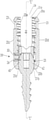
- FIG. 1 is an exploded view, with parts separated, of a polyaxial bone screw in accordance with the present disclosure
- FIG. 2A is a perspective view of the polyaxial bone screw of FIG. 1 with a set screw thereof removed for clarity;
- FIG. 2B is a side, perspective view of the set screw of the polyaxial bone screw of FIG. 1 ;
- FIG. 3 is a side view of the polyaxial bone screw of FIG. 2A ;
- FIG. 3A is a side view of a screw housing of the polyaxial bone screw of FIG. 1 ;
- FIG. 3B is a bottom perspective view of the polyaxial bone screw of FIG. 3 ;
- FIG. 4 is a cross-sectional view of the polyaxial bone screw of FIG. 3 taken along section line 4 - 4 ;
- FIG. 4A is a cross-sectional view of the screw housing of FIG. 3A taken along section line 4 A- 4 A;
- FIG. 5 is a front view of the polyaxial bone screw of FIG. 2A ;
- FIG. 5A is a bottom view of the polyaxial bone screw of FIG. 5 ;
- FIG. 6A is a side view of the polyaxial bone screw of FIG. 2A shown coupled to a spinal rod with the screw shaft depicted at a first angle relative to the screw housing;
- FIG. 6B is a side view of the polyaxial bone screw of FIG. 2A with the polyaxial bone screw depicted at a second angle relative to the screw housing;
- FIG. 7 is a perspective view of the polyaxial bone screw of FIG. 2A inserted into bone.
- FIG. 8 is a perspective view of the polyaxial bone screw of FIG. 6A .
- a polyaxial bone screw 10 generally includes a screw housing 20 , an anvil 30 , a spring 40 (e.g., a compression spring), a pin 50 , a screw 60 , and a set screw 70 .
- the polyaxial bone screw 10 is configured to be cooperatively engaged to a spinal rod “R” ( FIGS. 6A and 6B ).
- the screw housing 20 of the polyaxial bone screw 10 defines a longitudinal axis “L” and has a generally cylindrical shape.
- the screw housing 20 extends from a proximal end 20 a defining a proximal opening 21 a to a distal end 20 b defining a distal opening 21 b .
- the proximal and distal ends 20 a and 20 b , respectively, of the screw housing 20 may be disposed in parallel relation.
- the screw housing 20 further includes opposing first and second sidewalls 20 c , 20 d that extend proximally from the distal end 20 b of the basewall 20 f of the screw housing 20 and define a generally U-shaped rod-receiving channel 22 therebetween.
- Each of the first and second sidewalls 20 c , 20 d defines an external flanged recess 23 that is configured to facilitate grasping of the screw housing 20 by an instrument (not shown) that can also be used to facilitate insertion of the polyaxial bone screw 10 into a vertebral body.
- the annular basewall 20 f of the screw housing 20 extends distally to the distal end 20 b of the screw housing 20 .
- the screw housing 20 defines a threaded internal surface 20 e and a rod slot or rod-receiving channel 22 through a proximal portion of the screw housing 20 , and a central bore 24 through the screw housing 20 from the proximal opening 21 a defined in the proximal end 20 a of the screw housing 20 to the distal opening 21 b defined in the distal end 20 b of the screw housing 20 .
- the rod-receiving channel 22 is configured to receive a spinal rod “R” ( FIGS.
- the annular basewall 20 f of the screw housing 20 includes a central portion 20 g aligned with the rod-receiving channel 22 and first and second side portions 20 h , 20 i aligned with the first and second sidewalls 20 c , 20 d , respectively.
- the first side portion 20 h of the annular basewall 20 f defines a transverse hole 26 that receives the spring 40 and pin 50 .
- the transverse hole 26 is in communication with the bore 24 to enable the spring 40 to extend through the basewall 20 f and into the bore 24 .
- the central portion 20 g of the annular basewall 20 f includes a front wall 20 j and a back wall 20 k .
- the screw housing 20 defines a relief groove or notch 28 that may be milled out of the annular basewall 20 f .
- the notch 28 may be positioned at any suitable location along the basewall 20 f (e.g., back wall 20 k , first side portion 20 h , second side portion 20 i , etc.).
- the notch is shown disposed on front wall 20 j , such that when the screw pivots in the direction of the notch it pivots parallel to a rod disposed in the rod slot, the notch may be disposed in one of side walls 20 h , 20 i such that when the screw pivots in the direction of the notch it pivots perpendicular to or at an angle with respect to the direction of the rod slot, or a rod disposed in the rod slot.
- the notch 28 is defined by a planar surface 28 a connected to arcuate surfaces 28 b (e.g., defined by a diameter ranging from about 0.092 inches to about 0.096 inches in certain embodiments) disposed on opposite ends of the planar surface 28 a .
- Each of the arcuate surfaces 28 b extends distally from the planar surface 28 a to angled edges 28 c .
- the angled edges 28 c which in certain embodiments, may be angled about 45 degrees relative to the longitudinal axis “L,” extend to the distal end 20 b of the screw housing 20 .
- the diameter of the distal end 20 b of the screw housing 20 may be about 0.275 inches.
- the height of the notch 28 relative to distal end 20 b may range from about 0.034 inches to about 0.038 inches.
- the notch 28 is shown to extend along an arc angle of about 60 degrees (e.g., 30 degrees from centerline/midpoint thereof) around a circumference of the screw housing 20 , the notch 28 may, in some embodiments, extend around a greater or lesser arc angle, e.g., up to about 180 degrees.
- the arc angle may measure up to about 90 degrees.
- the arc angle may measure up to about 30 degrees.
- dimensions of the notch 28 will depend upon the amount of angulation and/or dimensions of screw 60 .
- the centerline/midpoint of the notch 28 may be aligned with an axis of the U-shaped rod-receiving channel 22 ( FIGS. 3A and 3B ). In some embodiments, the centerline/midpoint of the notch 20 may be positioned such that the notch 28 is rotationally offset from the axis defined by the U-shaped rod-receiving channel 22 .
- one or more of the dimensions of the notch 28 disclosed herein may be provided to enable the polyaxial bone screw 10 to achieve an increased angulation of about 15 degrees (e.g., up to 60 degrees in a first pivot angle as compared to 45 degrees in a second pivot angle).
- the ratios of two or more of the disclosed dimensions may be predefined to enable such increased/optimized angulation (e.g., height of notch 28 to degree of angulation).
- the annular basewall 20 f of the screw housing 20 further includes an internal surface 25 that defines a seat 25 a for supporting the head 62 of the screw member 60 at an internal location spaced-apart from, and proximal to, a distal end of the screw housing 20 .
- the seat 25 a extends to an inner edge 25 b , which may be C-shaped, and which includes first and second ends 25 c , 25 d that circumferentially terminate at the notch 28 .
- the inner edge 25 b is disposed adjacent to the angled edges 28 c of the notch 28 and the distal end 20 b of the screw housing 20 .
- the seat 25 a has a diameter ranging between about 0.219 inches to about 0.223 inches.
- the screw member 60 of the polyaxial bone screw 10 includes a head 62 (e.g., spherically-shaped) that is positioned in contact with the seat 25 a of the screw housing 20 to support the screw member 60 in the screw housing 20 , a neck 63 that extends distally from a distal end of the head 62 to a threaded shaft 64 .
- the threaded shaft 64 extends distally from a distal end of the neck 63 to a distal end of the screw member 60 .
- the head 62 includes a textured or uneven outer surface 62 a (e.g., annular ribs, ridges, etc.) that is configured to frictionally engage with the spring 40 while the spring 40 is engaged with the anvil 30 to maintain the screw member 60 in position relative to the screw housing 20 .
- the head 62 defines a driving recess 62 b (e.g., hexolobular or the like) defined in a proximal end thereof for receiving a driving tool (e.g., screw driver) (not shown) configured to screw the threaded shaft 64 of the screw member 60 into a hole in bone as the driving tool rotates the head 62 of the screw member 60 .
- a driving recess 62 b e.g., hexolobular or the like
- the screw member 60 while assembled to the screw housing 20 , is configured to be screwed to a vertebral body such as the lateral mass of the “atlas” vertebra (the “atlas” vertebra is anatomical parlance for the commonly designated C1 vertebra—not shown).
- the anvil 30 of the polyaxial bone screw 10 is threaded into the screw housing 20 and positioned on the head 62 of the screw member 60 and in locking engagement with the spring 40 .
- the anvil 30 includes an annular anvil body 32 , which may be cylindrically-shaped, and defines a saddle 34 configured to support the spinal rod “R” ( FIG. 6 ).
- the saddle 34 may be U-shaped.
- the annular anvil body 32 includes a threaded outer surface 32 a that is threadably engaged with the threaded internal surface 20 e of the screw housing 20 and positioned atop the head 62 of the screw member 60 .
- the threaded outer surface 32 a further includes a pair of side slots 32 b extending axially along the threaded outer surface 32 on opposed sides of the threaded outer surface 32 a .
- One of the slots 32 b receives the spring 40 to enable the spring 40 to rotatably lock the anvil 30 in position relative to the screw housing 20 such that the rod-receiving channel 22 of the screw housing 20 and the saddle 34 of the anvil 30 are aligned.
- the annular anvil body 32 defines a central opening 36 therethrough to provide screw-driving access to the drive recess 62 b of the screw member 60 .
- the screw housing 20 is configured to be polyaxially movable (e.g., pivotable and rotatable) relative to the screw member 60 , for example, to accommodate the spinal rod “R” at various angular and/or rotational orientations.
- the screw housing 20 is movable in a first direction relative to the screw member 60 to receive the neck 63 of the screw member 60 within the notch 28 .
- the screw member 60 is pivoted away from the longitudinal axis “L” of the screw housing 20 to define a first pivot angle “ ⁇ ” relative to the longitudinal axis “L”.
- first pivot angle “ ⁇ ” is shown to measure about 60 degrees, in certain embodiments, the first pivot angle “ ⁇ ” may range between 50 degrees to about 70 degrees, or more preferably between about 55 degrees to about 65 degrees. In some embodiments, the first pivot angle “ ⁇ ” may range between 45 degrees to about 90 degrees.
- the screw housing 20 is also movable in conical directions “CD” ( FIG. 2A ) relative to the screw member 60 that do not position the screw member 60 in registration with the notch 28 when the screw member 60 is pivoted away from the longitudinal axis “L.”
- These conical directions “CD” include medial-lateral directions (e.g., directions transverse to the spinal rod “R”) and (e.g., cranial-caudally and in-plane with spinal rod “R”— FIG. 7 ), at a second pivot angle “ ⁇ ”.
- the screw housing 20 is movable in a second direction (e.g., conical directions) relative to the screw member 60 to engage the neck 63 of the screw member 60 at the distal end 20 b of the screw housing 20 .
- the screw member 60 With the neck 63 engaged with the distal end 20 b , the screw member 60 is pivoted away from the longitudinal axis “L” of the screw housing 20 to define a second pivot angle “ ⁇ ” relative to the longitudinal axis “L”.
- the second pivot angle “ ⁇ ” is shown to measure about 45 degrees, in certain embodiments, the second pivot angle “ ⁇ ” may range between about 40 degrees to about 50 degrees. In some embodiments, the second pivot angle “ ⁇ ” may range between about 35 degrees to about 55 degrees.
- the notch 28 is configured to provide about 1 ⁇ 3 more angulation between the screw member 60 and the screw housing 20 in the first pivot angle “ ⁇ ” as compared to the second pivot angle “ ⁇ ”. Such arrangement helps to optimize angulation while maintaining structural integrity/strength of screw housing 20 .
- Manufacturing of the polyaxial bone screw 10 may involve machining the screw housing 20 , the anvil 30 , the pin 50 , the screw member 60 , and the set screw 70 in a lathe or screw machine.
- the notch 28 of the screw housing 20 may be notched out of the screw housing 20 in a separate milling operation.
- the spring 40 may be separately coiled.
- the threaded shaft 64 of the screw member 60 is passed through the screw housing 20 until the head 62 of the screw member 60 is rests on the seat 25 a of the screw housing 20 .
- the threaded outer surface 32 a of the anvil 30 is threaded along the threaded internal surface 20 e of the screw housing 20 until it seats onto the head 62 of the screw member 60 with the U-shaped saddle 34 of the anvil 30 aligned with the rod-receiving channel 22 of the screw housing 20 .
- the pin 50 and the spring 40 are then inserted into the transverse hole 26 of the screw housing 20 .
- a staking tool (not shown) may then utilized to deform the edges of the transverse hole 26 of the screw housing 20 to fixedly retain the pin 50 and the spring 40 in the transverse hole 26 such that the spring 40 is disposed in frictional engagement with one of the side slots 32 b of the anvil 30 and with the head 62 of the screw member 60 .
- the screw housing 20 of the polyaxial bone screw 10 can be movable relative to the screw member 60 through any of the angles detailed above to enable the screw housing 20 to receive the spinal rod “R” in the rod-receiving channel 22 of the screw housing 20 .
- the frictional engagement between the head 62 of the screw member 60 and the spring 40 helps maintain the screw member 60 and the screw housing 20 at a desired angular orientation with respect to one another.
- the spinal rod “R” can be secured to the polyaxial bone screw 10 by threading the set screw 70 into the screw housing 20 against the spinal rod “R,” as seen in FIG. 8 .
- the screw housing 20 and the spinal rod “R” therein can be further manipulated and/or pivoted relative to the screw member 60 to achieve a desired angular position of the spinal rod “R.”
- the set screw 70 can be fully tightened to fix the angular relationship between the screw housing 20 and the screw member 60 of the polyaxial bone screw 10 .
- the polyaxial bone screw system 10 may be formed from any suitable biocompatible material, including, for example, metals (e.g., a stainless steel, cobalt, chrome, titanium, and titanium alloy), polymers (e.g., PEEK, polyphenylsulfone, polyetherimide, polycarbonate, polyethylene, polypropylene, polyacetal, or other such engineering resin), or combinations of the aforementioned materials.
- metals e.g., a stainless steel, cobalt, chrome, titanium, and titanium alloy
- polymers e.g., PEEK, polyphenylsulfone, polyetherimide, polycarbonate, polyethylene, polypropylene, polyacetal, or other such engineering resin
Abstract
Description
Claims (18)
Priority Applications (2)
| Application Number | Priority Date | Filing Date | Title |
|---|---|---|---|
| US16/661,230 US11229459B2 (en) | 2017-07-31 | 2019-10-23 | Polyaxial bone screw with increased angulation |
| US17/574,783 US20220133364A1 (en) | 2017-07-31 | 2022-01-13 | Polyaxial Bone Screw With Increased Angulation |
Applications Claiming Priority (2)
| Application Number | Priority Date | Filing Date | Title |
|---|---|---|---|
| US15/664,398 US10610265B1 (en) | 2017-07-31 | 2017-07-31 | Polyaxial bone screw with increased angulation |
| US16/661,230 US11229459B2 (en) | 2017-07-31 | 2019-10-23 | Polyaxial bone screw with increased angulation |
Related Parent Applications (1)
| Application Number | Title | Priority Date | Filing Date |
|---|---|---|---|
| US15/664,398 Continuation US10610265B1 (en) | 2017-07-31 | 2017-07-31 | Polyaxial bone screw with increased angulation |
Related Child Applications (1)
| Application Number | Title | Priority Date | Filing Date |
|---|---|---|---|
| US17/574,783 Continuation US20220133364A1 (en) | 2017-07-31 | 2022-01-13 | Polyaxial Bone Screw With Increased Angulation |
Publications (2)
| Publication Number | Publication Date |
|---|---|
| US20200054366A1 US20200054366A1 (en) | 2020-02-20 |
| US11229459B2 true US11229459B2 (en) | 2022-01-25 |
Family
ID=69524205
Family Applications (3)
| Application Number | Title | Priority Date | Filing Date |
|---|---|---|---|
| US15/664,398 Active US10610265B1 (en) | 2017-07-31 | 2017-07-31 | Polyaxial bone screw with increased angulation |
| US16/661,230 Active 2038-02-14 US11229459B2 (en) | 2017-07-31 | 2019-10-23 | Polyaxial bone screw with increased angulation |
| US17/574,783 Pending US20220133364A1 (en) | 2017-07-31 | 2022-01-13 | Polyaxial Bone Screw With Increased Angulation |
Family Applications Before (1)
| Application Number | Title | Priority Date | Filing Date |
|---|---|---|---|
| US15/664,398 Active US10610265B1 (en) | 2017-07-31 | 2017-07-31 | Polyaxial bone screw with increased angulation |
Family Applications After (1)
| Application Number | Title | Priority Date | Filing Date |
|---|---|---|---|
| US17/574,783 Pending US20220133364A1 (en) | 2017-07-31 | 2022-01-13 | Polyaxial Bone Screw With Increased Angulation |
Country Status (1)
| Country | Link |
|---|---|
| US (3) | US10610265B1 (en) |
Families Citing this family (5)
| Publication number | Priority date | Publication date | Assignee | Title |
|---|---|---|---|---|
| US10610265B1 (en) * | 2017-07-31 | 2020-04-07 | K2M, Inc. | Polyaxial bone screw with increased angulation |
| US11369417B1 (en) | 2021-06-08 | 2022-06-28 | Curiteva, Inc. | Modular polyaxial pedicle screw assembly with split ring |
| WO2023086380A1 (en) * | 2021-11-11 | 2023-05-19 | Orthofix Us Llc | Friction-fit implantable devices and assemblies |
| CN114305639A (en) * | 2022-01-07 | 2022-04-12 | 洪琦 | Replacement device for retaining femoral neck and femoral head |
| US20230355280A1 (en) * | 2022-05-04 | 2023-11-09 | K2M, Inc. | Spinal Fixation System |
Citations (239)
| Publication number | Priority date | Publication date | Assignee | Title |
|---|---|---|---|---|
| US5669911A (en) | 1995-04-13 | 1997-09-23 | Fastenetix, L.L.C. | Polyaxial pedicle screw |
| WO1998012977A1 (en) | 1996-09-24 | 1998-04-02 | Sdgi Holdings, Inc. | Multi-axial bone screw assembly |
| WO1998049960A1 (en) | 1997-05-07 | 1998-11-12 | Aesculap-Jbs | Osteosynthesis system for vertebra arthrodesis |
| US5891145A (en) | 1997-07-14 | 1999-04-06 | Sdgi Holdings, Inc. | Multi-axial screw |
| US5989254A (en) | 1997-05-20 | 1999-11-23 | Katz; Akiva Raphael | Pedicle screw assembly |
| US6090111A (en) | 1998-06-17 | 2000-07-18 | Surgical Dynamics, Inc. | Device for securing spinal rods |
| US6280442B1 (en) | 1999-09-01 | 2001-08-28 | Sdgi Holdings, Inc. | Multi-axial bone screw assembly |
| US6485491B1 (en) | 2000-09-15 | 2002-11-26 | Sdgi Holdings, Inc. | Posterior fixation system |
| US6488681B2 (en) | 2001-01-05 | 2002-12-03 | Stryker Spine S.A. | Pedicle screw assembly |
| US6716214B1 (en) | 2003-06-18 | 2004-04-06 | Roger P. Jackson | Polyaxial bone screw with spline capture connection |
| US6736820B2 (en) | 2000-11-10 | 2004-05-18 | Biedermann Motech Gmbh | Bone screw |
| WO2005018471A1 (en) | 2003-08-20 | 2005-03-03 | Sdgi Holdings, Inc. | Multi-axial orthopedic device and system, e.g. for spinal surgery |
| US6869433B2 (en) | 2001-01-12 | 2005-03-22 | Depuy Acromed, Inc. | Polyaxial screw with improved locking |
| US20050096653A1 (en) | 2003-11-03 | 2005-05-05 | Doubler Robert L. | Bone fixation system with low profile fastener |
| US6905500B2 (en) | 2001-10-31 | 2005-06-14 | U & I Corporation | Bone fixation apparatus |
| US20050261687A1 (en) | 2004-04-20 | 2005-11-24 | Laszlo Garamszegi | Pedicle screw assembly |
| US20050267472A1 (en) | 2002-03-27 | 2005-12-01 | Biedermann Motech Gmbh | Bone anchoring device for stabilising bone segments and seat part of a bone anchoring device |
| US20060084987A1 (en) | 2004-10-20 | 2006-04-20 | Kim Daniel H | Systems and methods for posterior dynamic stabilization of the spine |
| US20060149235A1 (en) | 2004-12-20 | 2006-07-06 | Jackson Roger P | Medical implant fastener with nested set screw and method |
| US7087057B2 (en) | 2003-06-27 | 2006-08-08 | Depuy Acromed, Inc. | Polyaxial bone screw |
| US20060200136A1 (en) | 2005-02-22 | 2006-09-07 | Jackson Roger P | Bone attachment structure with engagement projections |
| US20060200131A1 (en) | 2005-03-04 | 2006-09-07 | Depuy Spine Sarl | Constrained motion bone screw assembly |
| US20060293665A1 (en) | 2002-02-13 | 2006-12-28 | Shluzas Alan E | Apparatus for connecting a longitudinal member to a bone portion |
| US20070123870A1 (en) | 2005-07-18 | 2007-05-31 | Jeon Dong M | Bi-polar screw assembly |
| US7250052B2 (en) | 2002-10-30 | 2007-07-31 | Abbott Spine Inc. | Spinal stabilization systems and methods |
| US7264621B2 (en) | 2004-06-17 | 2007-09-04 | Sdgi Holdings, Inc. | Multi-axial bone attachment assembly |
| US20070208344A1 (en) | 2006-03-01 | 2007-09-06 | Sdgi Holdings, Inc. | Devices for securing elongated spinal connecting elements in bone anchors |
| US20070233078A1 (en) | 2006-01-27 | 2007-10-04 | Justis Jeff R | Pivoting joints for spinal implants including designed resistance to motion and methods of use |
| US20070233086A1 (en) | 2006-01-11 | 2007-10-04 | Jurgen Harms | Bone anchoring assembly |
| US20080015596A1 (en) | 2006-04-28 | 2008-01-17 | Whipple Dale E | Large diameter multiple piece bone anchor assembly |
| US20080015579A1 (en) | 2006-04-28 | 2008-01-17 | Whipple Dale E | Large diameter bone anchor assembly |
| US7322981B2 (en) | 2003-08-28 | 2008-01-29 | Jackson Roger P | Polyaxial bone screw with split retainer ring |
| US20080039843A1 (en) | 2006-08-11 | 2008-02-14 | Abdou M S | Spinal motion preservation devices and methods of use |
| US20080058811A1 (en) | 2002-04-09 | 2008-03-06 | Nas Medical Technologies, Inc. | Bone fixation apparatus |
| US7377923B2 (en) | 2003-05-22 | 2008-05-27 | Alphatec Spine, Inc. | Variable angle spinal screw assembly |
| US20080154315A1 (en) | 2005-02-22 | 2008-06-26 | Jackson Roger P | Polyaxial bone screw with spherical capture, compression and alignment and retention structures |
| US20080177335A1 (en) | 2006-10-26 | 2008-07-24 | Warsaw Orthopedic Inc. | Bone screw |
| US20080177321A1 (en) * | 2006-10-17 | 2008-07-24 | Warsaw Orthopedic, Inc. | Multi-axial bone attachment member |
| US20080200956A1 (en) | 2007-02-19 | 2008-08-21 | Tutela Medicus, Llc | Low Profile Orthopedic Fastener Assembly Having Enhanced Flexibility |
| US20080269809A1 (en) | 2007-03-26 | 2008-10-30 | Laszlo Garamszegi | Bottom-loading pedicle screw assembly |
| US20080306534A1 (en) | 2007-06-05 | 2008-12-11 | Spartek Medical, Inc. | Dual deflection rod system for a dynamic stabilization and motion preservation spinal implantation system and method |
| US7476239B2 (en) | 2005-05-10 | 2009-01-13 | Jackson Roger P | Polyaxial bone screw with compound articulation |
| US20090018591A1 (en) | 2005-01-31 | 2009-01-15 | Hawkes David T | Polyaxial Pedicle Screw Assembly |
| US20090062866A1 (en) | 2003-06-18 | 2009-03-05 | Jackson Roger P | Polyaxial bone anchor with helical capture connection, insert and dual locking assembly |
| US20090076552A1 (en) | 2007-09-17 | 2009-03-19 | Clariance | Vertebral anchoring device |
| US20090093844A1 (en) | 2005-09-30 | 2009-04-09 | Jackson Roger P | Elastic covered dynamic stabilization connector and assembly |
| US20090105769A1 (en) | 2007-10-22 | 2009-04-23 | Andy Rock | Uni-planar, taper lock bone screw |
| US20090105770A1 (en) | 2007-10-23 | 2009-04-23 | Gregory Berrevoets | Rod Coupling Assembly and Methods for Bone Fixation |
| US7572279B2 (en) | 2004-11-10 | 2009-08-11 | Jackson Roger P | Polyaxial bone screw with discontinuous helically wound capture connection |
| US20090254125A1 (en) | 2008-04-03 | 2009-10-08 | Daniel Predick | Top Loading Polyaxial Spine Screw Assembly With One Step Lockup |
| US7625394B2 (en) | 2005-08-05 | 2009-12-01 | Warsaw Orthopedic, Inc. | Coupling assemblies for spinal implants |
| US20090326582A1 (en) | 2008-04-10 | 2009-12-31 | Marcus Songer | Dynamic Rod |
| US7678137B2 (en) | 2004-01-13 | 2010-03-16 | Life Spine, Inc. | Pedicle screw constructs for spine fixation systems |
| US7686834B2 (en) | 2001-03-15 | 2010-03-30 | Stryker Spine | Anchoring member with safety ring |
| US20100087873A1 (en) | 2008-10-06 | 2010-04-08 | Warsaw Orthopedics, Inc. | Surgical Connectors for Attaching an Elongated Member to a Bone |
| US7695497B2 (en) | 2005-09-12 | 2010-04-13 | Seaspine, Inc. | Implant system for osteosynthesis |
| US20100094349A1 (en) | 2004-08-27 | 2010-04-15 | Michael Hammer | Multi-Axial Connection System |
| US7699876B2 (en) | 2006-11-08 | 2010-04-20 | Ebi, Llc | Multi-axial bone fixation apparatus |
| US20100114180A1 (en) | 2008-11-05 | 2010-05-06 | K2M, Inc. | Multi-planar, taper lock screw with additional lock |
| US20100137920A1 (en) | 2007-05-16 | 2010-06-03 | Hammill Sr John E | Pedicle screw implant system |
| US7749258B2 (en) | 2005-10-12 | 2010-07-06 | Biedermann Motech Gmbh | Bone anchoring device |
| US20100191293A1 (en) | 2003-06-18 | 2010-07-29 | Jackson Roger P | Polyaxial bone anchor with spline capture connection and lower pressure insert |
| US20100204738A1 (en) | 2005-07-29 | 2010-08-12 | X-Spine Systems, Inc. | Capless multiaxial screw and spinal fixation assembly and method |
| US7776067B2 (en) | 2005-05-27 | 2010-08-17 | Jackson Roger P | Polyaxial bone screw with shank articulation pressure insert and method |
| US20100234902A1 (en) | 2009-02-20 | 2010-09-16 | Lutz Biedermann | Receiving part for receiving a rod for coupling the rod to a bone anchoring element and a bone anchoring device with such a receiving part |
| US20100241175A1 (en) | 2009-03-20 | 2010-09-23 | Spinal USA LLC | Pedicle screws and methods of using the same |
| WO2010111470A1 (en) | 2009-03-25 | 2010-09-30 | Simonson Peter M | Variable height, multi-axial bone screw assembly |
| US20100262196A1 (en) | 2007-10-23 | 2010-10-14 | K2M, Inc. | Posterior pedicle screw having a taper lock |
| US20100298891A1 (en) | 2004-11-23 | 2010-11-25 | Jackson Roger P | Bone anchors with longitudinal connecting member engaging inserts and closures for fixation and optional angulation |
| US20100305621A1 (en) | 2009-06-02 | 2010-12-02 | Alphatec Spine, Inc. | Bone screw assembly for limited angulation |
| US20100312279A1 (en) | 2006-08-23 | 2010-12-09 | Gephart Matthew P | Minimally Invasive Surgical System |
| US20100331886A1 (en) | 2009-06-25 | 2010-12-30 | Jonathan Fanger | Posterior Dynamic Stabilization Device Having A Mobile Anchor |
| US7879075B2 (en) | 2002-02-13 | 2011-02-01 | Zimmer Spine, Inc. | Methods for connecting a longitudinal member to a bone portion |
| US20110040338A1 (en) | 2003-08-28 | 2011-02-17 | Jackson Roger P | Polyaxial bone anchor having an open retainer with conical, cylindrical or curvate capture |
| US7901435B2 (en) | 2004-05-28 | 2011-03-08 | Depuy Spine, Inc. | Anchoring systems and methods for correcting spinal deformities |
| US20110077694A1 (en) | 2009-09-25 | 2011-03-31 | Lutz Biedermann | Bone anchoring device |
| US7922748B2 (en) | 2006-06-16 | 2011-04-12 | Zimmer Spine, Inc. | Removable polyaxial housing for a pedicle screw |
| US20110087288A1 (en) | 2007-10-24 | 2011-04-14 | Tara Stevenson | Surgical Fixation System and Related Methods |
| US7927360B2 (en) | 2006-01-26 | 2011-04-19 | Warsaw Orthopedic, Inc. | Spinal anchor assemblies having extended receivers |
| WO2011047251A1 (en) | 2009-10-16 | 2011-04-21 | Depuy Spine, Inc. | Bone anchor assemblies and methods of manufacturing and use thereof |
| US20110098755A1 (en) | 2009-06-15 | 2011-04-28 | Jackson Roger P | Polyaxial bone anchor with non-pivotable retainer and pop-on shank, some with friction fit |
| US20110106175A1 (en) | 2009-10-30 | 2011-05-05 | Warsaw Orthopedic, Inc. | Bone Engaging Implant With Adjustment Saddle |
| US20110106176A1 (en) | 2004-11-23 | 2011-05-05 | Jackson Roger P | Polyaxial bone screw with multi-part shank retainer and pressure insert |
| US20110112578A1 (en) | 2009-11-09 | 2011-05-12 | Ebi, Llc | Multiplanar bone anchor system |
| US7942911B2 (en) | 2007-05-16 | 2011-05-17 | Ortho Innovations, Llc | Polyaxial bone screw |
| US7942910B2 (en) | 2007-05-16 | 2011-05-17 | Ortho Innovations, Llc | Polyaxial bone screw |
| US7947065B2 (en) | 2008-11-14 | 2011-05-24 | Ortho Innovations, Llc | Locking polyaxial ball and socket fastener |
| US20110125196A1 (en) | 2009-11-23 | 2011-05-26 | Felix Quevedo | CAM Lock Pedicle Screw |
| US7967849B2 (en) | 2007-04-06 | 2011-06-28 | Warsaw Orthopedic, Inc. | Adjustable multi-axial spinal coupling assemblies |
| US20110178558A1 (en) | 2010-01-15 | 2011-07-21 | Ebi, Llc | Uniplanar bone anchor system |
| US20110184474A1 (en) | 2008-09-09 | 2011-07-28 | Richelsoph Marc E | Polyaxial screw assembly |
| US20110251650A1 (en) | 2010-03-29 | 2011-10-13 | Lutz Biedermann | Bone anchoring device |
| US20110257690A1 (en) | 2010-04-20 | 2011-10-20 | Warsaw Orthopedic, Inc. | Transverse and Sagittal Adjusting Screw |
| US8048126B2 (en) | 2005-10-20 | 2011-11-01 | Ebi, Llc | Bone fixation assembly |
| US20110270321A1 (en) | 2010-04-30 | 2011-11-03 | Warsaw Orthopedic, Inc. | Engaging Member With a Cavity-Base for Engaging a Connecting Element to a Bone Anchor |
| US8057519B2 (en) | 2006-01-27 | 2011-11-15 | Warsaw Orthopedic, Inc. | Multi-axial screw assembly |
| US20110282399A1 (en) | 2007-01-22 | 2011-11-17 | Jackson Roger P | Polyaxial bone screw with cam connection and lock and release insert |
| US20110282402A1 (en) | 2005-03-04 | 2011-11-17 | Depuy Spine, Inc. | Instruments and methods for manipulating vertebra |
| US8070774B2 (en) | 2007-06-05 | 2011-12-06 | Spartek Medical, Inc. | Reinforced bone anchor for a dynamic stabilization and motion preservation spinal implantation system and method |
| US20110301650A1 (en) | 2005-10-18 | 2011-12-08 | Warsaw Orthopedic, Inc. | Adjsutable bone anchor asembly |
| US20110301651A1 (en) | 2007-12-19 | 2011-12-08 | X-Spine Systems, Inc. | Offset multiaxial or polyaxial screw, system and assembly |
| US20110301646A1 (en) | 2010-01-05 | 2011-12-08 | The Johns Hopkins University | Compression-distraction spinal fixation system |
| US8075603B2 (en) | 2008-11-14 | 2011-12-13 | Ortho Innovations, Llc | Locking polyaxial ball and socket fastener |
| US8080036B2 (en) | 2008-10-09 | 2011-12-20 | Korea Bone Bank, Inc. | Pedicle screw |
| US20110319946A1 (en) | 2009-03-12 | 2011-12-29 | Levy Mark M | Bone implantation and stabilization assembly including deployment device |
| US20110319939A1 (en) | 2010-01-05 | 2011-12-29 | Neuraxis Technologies LLC | Compression-distraction spinal fixation system and kit |
| US8092502B2 (en) | 2003-04-09 | 2012-01-10 | Jackson Roger P | Polyaxial bone screw with uploaded threaded shank and method of assembly and use |
| US8097025B2 (en) | 2005-10-25 | 2012-01-17 | X-Spine Systems, Inc. | Pedicle screw system configured to receive a straight or curved rod |
| US20120016425A1 (en) | 2009-11-09 | 2012-01-19 | Ebi, Llc | Multiplanar bone anchor system |
| US8100946B2 (en) | 2005-11-21 | 2012-01-24 | Synthes Usa, Llc | Polyaxial bone anchors with increased angulation |
| US8100916B2 (en) | 2005-07-21 | 2012-01-24 | Depuy Spine, Inc. | Instrument for inserting, adjusting and removing a surgical implant |
| US20120035670A1 (en) | 2009-06-15 | 2012-02-09 | Jackson Roger P | Polyaxial bone anchors with pop-on shank, fully constrained friction fit retainer and lock and release insert |
| US20120035663A1 (en) | 2003-04-09 | 2012-02-09 | Jackson Roger P | Dynamic stabilization medical implant assemblies and methods |
| US20120046699A1 (en) | 2010-08-20 | 2012-02-23 | K2M, Inc. | Spinal fixation system |
| US20120046700A1 (en) | 2009-06-15 | 2012-02-23 | Jackson Roger P | Polyaxial bone anchor with pop-on shank and pivotable retainer |
| US20120059426A1 (en) | 2008-08-01 | 2012-03-08 | Jackson Roger P | Polyaxial bone anchors with pop-on shank, friction fit fully restrained retainer, insert and tool receiving features |
| US8142481B2 (en) | 2004-10-25 | 2012-03-27 | X-Spine Systems, Inc. | Pedicle screw systems and methods of assembling/installing the same |
| US20120089196A1 (en) | 2003-06-18 | 2012-04-12 | Jackson Roger P | Upload shank swivel head bone screw spinal implant |
| US8162989B2 (en) | 2002-11-04 | 2012-04-24 | Altus Partners, Llc | Orthopedic rod system |
| US8167910B2 (en) | 2006-10-16 | 2012-05-01 | Innovative Delta Technology Llc | Bone screw and associated assembly and methods of use thereof |
| US20120109218A1 (en) | 2010-10-29 | 2012-05-03 | Warsaw Orthopedic, Inc. | Directional Control for a Multi-Axial Screw Assembly |
| US20120123486A1 (en) | 2010-11-15 | 2012-05-17 | Werner Claudia Mack | Pedicle-screw assembly |
| US20120143262A1 (en) | 2010-12-01 | 2012-06-07 | Deru Gmbh | Variable angle bone screw fixation arrangement |
| US20120143265A1 (en) | 2010-11-22 | 2012-06-07 | Lutz Biedermann | Polyaxial bone anchoring device |
| US20120143266A1 (en) | 2009-06-15 | 2012-06-07 | Jackson Roger P | Polyaxial bone anchor with open planar retainer, pop-on shank and friction fit insert |
| US8197517B1 (en) | 2007-05-08 | 2012-06-12 | Theken Spine, Llc | Frictional polyaxial screw assembly |
| US20120165881A1 (en) | 2010-12-23 | 2012-06-28 | Lutz Biedermann | Bone anchoring device |
| US20120197313A1 (en) | 2011-01-28 | 2012-08-02 | Warsaw Orthopedic, Inc. | Angled Receiver Wall for Provisionally Fixing a Crown in a Multi-Axial Screw Assembly |
| US20120197314A1 (en) | 2011-01-28 | 2012-08-02 | Warsaw Orthopedic, Inc. | Provisional fixation for a multi-axial screw assembly |
| US8236035B1 (en) | 2009-06-16 | 2012-08-07 | Bedor Bernard M | Spinal fixation system and method |
| US20120209335A1 (en) | 2011-02-11 | 2012-08-16 | Blackstone Medical, Inc. | Multi-axial pedicle fixation assembly and method for use |
| US20120215263A1 (en) | 2011-02-23 | 2012-08-23 | Choon Sung Lee | Extensible pedicle screw coupling device |
| US8257399B2 (en) | 2007-12-13 | 2012-09-04 | Biedermann Technologies Gmbh & Co. Kg | Anchoring device for anchoring a rod in bones or vertebrae |
| US20120232598A1 (en) * | 2011-03-09 | 2012-09-13 | Zimmer Spine, Inc. | Polyaxial pedicle screw with increased angulation |
| US8267968B2 (en) | 2009-06-24 | 2012-09-18 | Neuropro Technologies, Inc. | Percutaneous system for dynamic spinal stabilization |
| US8267978B2 (en) | 2006-09-14 | 2012-09-18 | Warsaw Orthopedic, Inc. | Hybrid bone fixation apparatus |
| US8277490B2 (en) | 2007-08-31 | 2012-10-02 | University Of South Florida | Translational manipulation polyaxial screw head |
| US8292934B2 (en) | 2008-10-17 | 2012-10-23 | Warsaw Orthopedic, Inc. | Dynamic anchor assembly for connecting elements in spinal surgical procedures |
| US8317833B2 (en) | 2007-03-23 | 2012-11-27 | Coligne Ag | Elongated stabilization member and bone anchor useful in bone and especially spinal repair processes |
| US20120310284A1 (en) | 2011-06-03 | 2012-12-06 | Royal Oak Industries | Polyaxial pedicle screw |
| US20130013003A1 (en) | 2010-02-23 | 2013-01-10 | K2M, Inc. | Polyaxial bonescrew assembly |
| US8353932B2 (en) | 2005-09-30 | 2013-01-15 | Jackson Roger P | Polyaxial bone anchor assembly with one-piece closure, pressure insert and plastic elongate member |
| US8361129B2 (en) | 2006-04-28 | 2013-01-29 | Depuy Spine, Inc. | Large diameter bone anchor assembly |
| US8366753B2 (en) | 2003-06-18 | 2013-02-05 | Jackson Roger P | Polyaxial bone screw assembly with fixed retaining structure |
| US20130046345A1 (en) | 2010-08-20 | 2013-02-21 | K2M, Inc. | Spinal fixation system |
| US20130046350A1 (en) | 2009-06-15 | 2013-02-21 | Roger P. Jackson | Polyaxial bone anchor with pop-on shank, shank, friction fit retainer, winged insert and low profile edge lock |
| US8382811B2 (en) | 2009-06-19 | 2013-02-26 | U.S. Spine, Inc. | Triple lead bone screw |
| US20130053892A1 (en) | 2011-08-31 | 2013-02-28 | Depuy Spine, Inc. | System and method for cervical midline fixation |
| US20130065698A1 (en) | 2008-04-22 | 2013-03-14 | Biedermann Technologies Gmbh & Co. Kg | Instrument for assembling a bone anchoring device |
| US8403962B2 (en) | 2005-02-22 | 2013-03-26 | Roger P. Jackson | Polyaxial bone screw assembly |
| US8409256B2 (en) | 2006-12-28 | 2013-04-02 | Depuy Spine, Inc. | Spinal anchoring screw |
| US20130096618A1 (en) | 2011-10-14 | 2013-04-18 | Thibault Chandanson | Bone anchor assemblies |
| US20130096622A1 (en) | 2011-08-18 | 2013-04-18 | Timo Biedermann | Polyaxial bone anchoring device |
| US20130103098A1 (en) | 2009-06-15 | 2013-04-25 | Roger P. Jackson | Polyaxial bone anchor with pop-on shank, friction fit retainer and lateral alignment feature |
| US20130110176A1 (en) | 2011-11-02 | 2013-05-02 | Warsaw Orthopedic, Inc. | Implant assembly with a rigid interface |
| US20130110178A1 (en) | 2011-10-27 | 2013-05-02 | Biedermann Technologies Gmbh & Co. Kg | High angulation polyaxial bone anchoring device |
| US20130123858A1 (en) | 2010-04-23 | 2013-05-16 | Smartspine | Multiaxial pedicle attachment device for vertebral osteosynthesis |
| US8449577B2 (en) | 2005-02-08 | 2013-05-28 | Henning Kloss | Spine fixator |
| US20130165977A1 (en) | 2011-12-23 | 2013-06-27 | Biedermann Technologies Gmbh & Co. Kg | Polyaxial bone anchoring device |
| US8475495B2 (en) | 2004-04-08 | 2013-07-02 | Globus Medical | Polyaxial screw |
| US8506600B2 (en) | 2001-09-14 | 2013-08-13 | Stryker Spine | Methods for stabilizing bone using spinal fixation devices |
| US8512380B2 (en) | 2002-08-28 | 2013-08-20 | Warsaw Orthopedic, Inc. | Posterior fixation system |
| US20130218207A1 (en) * | 2012-02-16 | 2013-08-22 | Warsaw Orthopedic, Inc | Dynamic multi-axial anchor |
| US20130226243A1 (en) | 2010-04-30 | 2013-08-29 | Kilian Kraus | Pedicle screw and device and method for stabilizing the spinal column |
| US8574274B2 (en) | 2008-12-02 | 2013-11-05 | Eminent Spine Llc | Pedicle screw fixation system and method for use of same |
| US20130338721A1 (en) | 2012-05-29 | 2013-12-19 | Biedermann Technologies Gmbh & Co. Kg | Receiving part for receiving a rod for coupling the rod to a bone anchoring element and a bone anchoring device with such a receiving part |
| US20140025119A1 (en) | 2012-07-18 | 2014-01-23 | Biedermann Technologies GmbH & Co., KG | Polyaxial bone anchoring device |
| US20140025120A1 (en) | 2012-07-18 | 2014-01-23 | Warsaw Orthopedic, Inc. | Multi-axial bone fastener and system |
| US8636778B2 (en) | 2009-02-11 | 2014-01-28 | Pioneer Surgical Technology, Inc. | Wide angulation coupling members for bone fixation system |
| US8663291B2 (en) | 2011-10-28 | 2014-03-04 | Ortho Innovations, Llc | Top loading polyaxial ball and socket fastener |
| US8663290B2 (en) | 2011-10-28 | 2014-03-04 | Ortho Innovations, Llc | Top loading polyaxial ball and socket fastener with saddle |
| US20140094849A1 (en) | 2012-09-28 | 2014-04-03 | Frank Spratt | Bone Anchor Assemblies |
| US8690925B2 (en) | 2011-08-05 | 2014-04-08 | Biedermann Technologies Gmbh & Co. Kg | Locking device for locking a rod-shaped element in a receiving part of a bone anchor and bone anchor with such a locking device |
| US8709051B2 (en) | 2004-08-27 | 2014-04-29 | Blackstone Medical, Inc. | Multi-axial connection system |
| US20140142634A1 (en) | 2012-11-16 | 2014-05-22 | DePuy Synthes Products, LLC | Bone fixation assembly |
| US8740947B2 (en) | 2006-02-15 | 2014-06-03 | Warsaw, Orthopedic, Inc. | Multiple lead bone fixation apparatus |
| US20140214084A1 (en) | 2013-01-28 | 2014-07-31 | Roger P. Jackson | Polyaxial bone anchor with receiver with spheric edge for friction fit |
| US8795337B2 (en) | 2009-10-30 | 2014-08-05 | Warsaw Orthopedic, Inc. | Apparatus for implementing a spinal fixation system with supplemental fixation |
| US20140228887A1 (en) | 2013-02-09 | 2014-08-14 | Muralidhara Rudhra Raju | Bone screw |
| US20140277152A1 (en) | 2013-03-15 | 2014-09-18 | Blackstone Medical, Inc. | Hook with rotating saddle and rotatable mono axial pedicle screw |
| US20140277158A1 (en) | 2013-03-14 | 2014-09-18 | DePuy Synthes Products, LLC | Bottom-loading bone anchor assemblies and methods |
| US20140277153A1 (en) | 2013-03-14 | 2014-09-18 | DePuy Synthes Products, LLC | Bone Anchor Assemblies and Methods With Improved Locking |
| US20140277161A1 (en) | 2013-03-14 | 2014-09-18 | Medos International Sarl | Bone Anchor Assemblies and Methods With Improved Locking |
| US20140277159A1 (en) | 2013-03-14 | 2014-09-18 | DePuy Synthes Products, LLC | Bottom-loading bone anchor assemblies |
| US20140296920A1 (en) | 2005-08-03 | 2014-10-02 | Biedermann Technologies Gmbh & Co. Kg | Bone anchoring device |
| US8870927B2 (en) | 2005-07-12 | 2014-10-28 | Biedermann Technologies Gmbh & Co. Kg | Bone anchoring device |
| US20140343617A1 (en) | 2013-04-12 | 2014-11-20 | Alphatec Spine, Inc. | Uniplanar screw assembly and methods of use |
| US20140358182A1 (en) | 2011-10-05 | 2014-12-04 | Aesculap Ag | Readjustable polyaxial pedicle screw |
| US8906068B1 (en) | 2011-09-13 | 2014-12-09 | Bernard M. Bedor | Spinal fixation system and method |
| US8911484B2 (en) | 2006-05-18 | 2014-12-16 | Wei Lei | Multi-axial expandable pedicle screw and an expansion method thereof |
| US20150025579A1 (en) | 2013-07-19 | 2015-01-22 | Lutz Biedermann | Polyaxial bone anchoring device |
| US20150032162A1 (en) | 2013-07-24 | 2015-01-29 | Biedermann Technologies Gmbh & Co. Kg | Coupling assembly for coupling a rod to a bone anchoring element, kit of such a coupling assembly different rod receiving elements and bone anchoring device |
| US8951294B2 (en) | 2009-03-12 | 2015-02-10 | Euros | Spinal implant with a lockable ball joint |
| US8961568B2 (en) | 2007-01-12 | 2015-02-24 | Lanx, Inc. | Bone fastener assembly |
| US20150080960A1 (en) | 2013-09-19 | 2015-03-19 | Lutz Biedermann | Coupling assembly for coupling a rod to a bone anchoring element, polyaxial bone anchoring device and modular stabilization device |
| US8986349B1 (en) | 2009-11-11 | 2015-03-24 | Nuvasive, Inc. | Systems and methods for correcting spinal deformities |
| US20150088202A1 (en) | 2013-09-25 | 2015-03-26 | Blackstone Medical, Inc. | Bone screw systems with pressure caps having biasing members |
| US8998958B2 (en) | 2007-12-20 | 2015-04-07 | Aesculap Implant Systems, Llc | Locking device introducer instrument |
| US20150119942A1 (en) | 2004-11-10 | 2015-04-30 | Roger P. Jackson | Splay control closure for open bone anchor |
| US20150134006A1 (en) | 2013-11-08 | 2015-05-14 | Blackstone Medical, Inc. | Lockable Pedicle Fastener |
| US20150142059A1 (en) | 2013-11-14 | 2015-05-21 | Lutz Biedermann | Polyaxial bone anchoring device with enlarged pivot angle |
| US20150148848A1 (en) | 2013-11-27 | 2015-05-28 | Spinal Llc | Bottom loading low profile fixation system |
| US9060814B2 (en) | 2011-10-28 | 2015-06-23 | Ortho Innovations, Llc | Spring clip bottom loading polyaxial ball and socket fastener |
| US20150182261A1 (en) | 2013-12-31 | 2015-07-02 | Blackstone Medical, Inc. | Translational pedicle screw systems |
| US20150190176A1 (en) | 2014-01-09 | 2015-07-09 | Roger P Jackson | Bi-radial pop-on cervical bone anchor |
| US20150196338A1 (en) | 2014-01-13 | 2015-07-16 | Lutz Biedermann | Coupling assembly for coupling a rod to a bone anchoring element, and polyaxial bone anchoring device |
| US20150196337A1 (en) | 2014-01-13 | 2015-07-16 | Lutz Biedermann | Coupling assembly for coupling a rod to a bone anchoring element, and polyaxial bone anchoring device |
| US9084634B1 (en) | 2010-07-09 | 2015-07-21 | Theken Spine, Llc | Uniplanar screw |
| US20150201972A1 (en) | 2013-07-18 | 2015-07-23 | Ortho Innovations, Llc | Spring clip bottom loading polyaxial ball and socket fastener |
| US20150230829A1 (en) | 2014-02-17 | 2015-08-20 | FloSpine LLC | Polyaxial bone anchor incorporating a two position saddle assembly |
| US9119673B2 (en) | 2005-06-17 | 2015-09-01 | Us Spine, Inc. | Spinal correction system with multi-stage locking mechanism |
| US9131972B2 (en) | 2011-11-30 | 2015-09-15 | L&K Biomed Co., Ltd. | Screw for fixing vertebra |
| US20150282844A1 (en) | 2014-04-03 | 2015-10-08 | Zimmer Spine, Inc. | Uniplanar bone screw |
| US20150282843A1 (en) | 2014-04-02 | 2015-10-08 | FloSpine LLC | Polyaxial bone anchor incorporating a threaded bone screw and compression saddle |
| US9168069B2 (en) | 2009-06-15 | 2015-10-27 | Roger P. Jackson | Polyaxial bone anchor with pop-on shank and winged insert with lower skirt for engaging a friction fit retainer |
| US20150320465A1 (en) | 2014-05-06 | 2015-11-12 | Warsaw Orthopedic, Inc. | Bone fastener and methods of use |
| US9192417B2 (en) | 2011-12-13 | 2015-11-24 | Biedermann Technologies Gmbh & Co. Kg | Monoplanar bone anchoring device with selectable pivot plane |
| US9216041B2 (en) | 2009-06-15 | 2015-12-22 | Roger P. Jackson | Spinal connecting members with tensioned cords and rigid sleeves for engaging compression inserts |
| US20160015429A1 (en) | 2014-07-18 | 2016-01-21 | Warsaw Orthopedic, Inc. | Bone fastener and methods of use |
| US9247965B2 (en) | 2011-08-18 | 2016-02-02 | Biedermann Technologies Gmbh & Co. Kg | Polyaxial bone anchoring device with enlarged pivot angle |
| US20160030090A1 (en) | 2014-07-29 | 2016-02-04 | Transcendental Spine, Llc | Modular polyaxial bone screw |
| US9259247B2 (en) | 2013-03-14 | 2016-02-16 | Medos International Sarl | Locking compression members for use with bone anchor assemblies and methods |
| US9277938B2 (en) | 2011-08-18 | 2016-03-08 | Biedermann Technologies Gmbh & Co. Kg | Polyaxial bone anchoring system |
| US9277942B2 (en) | 2012-07-27 | 2016-03-08 | Biedermann Technologies Gmbh & Co. Kg | Polyaxial bone anchoring device with enlarged pivot angle |
| US9358047B2 (en) | 2011-07-15 | 2016-06-07 | Globus Medical, Inc. | Orthopedic fixation devices and methods of installation thereof |
| US20160183982A1 (en) | 2013-05-02 | 2016-06-30 | Spinevision | Bottom-Loading Polyaxial Bone Anchoring System |
| US20160206357A1 (en) | 2015-01-20 | 2016-07-21 | Amendia, Inc. | Modular pedicle screw assembly with a snap tulip |
| US20160296256A1 (en) | 2015-04-13 | 2016-10-13 | Medos International Sarl | Bone anchor assemblies with orientation indicator |
| US9504494B2 (en) | 2008-04-28 | 2016-11-29 | DePuy Synthes Products, Inc. | Implants for securing spinal fixation elements |
| US20170020576A1 (en) | 2014-04-10 | 2017-01-26 | Medacta International Sa | Device for fixing surgical implants in place and relative assembly procedure with anchoring means |
| US20170049482A1 (en) | 2015-08-17 | 2017-02-23 | Spinal Usa, Inc. | Spinal screws and methods of using the same |
| US9597121B2 (en) | 2012-01-30 | 2017-03-21 | Biedermann Technologies Gmbh & Co. Kg | Bone anchoring device |
| US9603632B1 (en) * | 2016-05-20 | 2017-03-28 | Amendia, Inc. | Tulip bone screw assembly |
| US9700355B2 (en) | 2011-11-23 | 2017-07-11 | Aaron M. Longtain | Pedicle screw assembly |
| US20170281241A1 (en) | 2014-10-21 | 2017-10-05 | Roger P. Jackson | Bone anchor having a snap-fit assembly |
| US20170311988A1 (en) | 2014-10-20 | 2017-11-02 | Safe Orthopaedics | Polyaxial vertebral anchoring device for straightening a vertebra |
| US20180263662A1 (en) | 2017-03-17 | 2018-09-20 | National Yang-Ming University | Pedicle screw system with single plane motion and axial rotation |
| US20180325569A1 (en) | 2017-05-10 | 2018-11-15 | Medos International Sarl | Bone anchors with drag features and related methods |
| US10610265B1 (en) * | 2017-07-31 | 2020-04-07 | K2M, Inc. | Polyaxial bone screw with increased angulation |
-
2017
- 2017-07-31 US US15/664,398 patent/US10610265B1/en active Active
-
2019
- 2019-10-23 US US16/661,230 patent/US11229459B2/en active Active
-
2022
- 2022-01-13 US US17/574,783 patent/US20220133364A1/en active Pending
Patent Citations (364)
| Publication number | Priority date | Publication date | Assignee | Title |
|---|---|---|---|---|
| US5669911A (en) | 1995-04-13 | 1997-09-23 | Fastenetix, L.L.C. | Polyaxial pedicle screw |
| WO1998012977A1 (en) | 1996-09-24 | 1998-04-02 | Sdgi Holdings, Inc. | Multi-axial bone screw assembly |
| WO1998049960A1 (en) | 1997-05-07 | 1998-11-12 | Aesculap-Jbs | Osteosynthesis system for vertebra arthrodesis |
| US5989254A (en) | 1997-05-20 | 1999-11-23 | Katz; Akiva Raphael | Pedicle screw assembly |
| US5891145A (en) | 1997-07-14 | 1999-04-06 | Sdgi Holdings, Inc. | Multi-axial screw |
| US6090111A (en) | 1998-06-17 | 2000-07-18 | Surgical Dynamics, Inc. | Device for securing spinal rods |
| US8298274B2 (en) | 1999-09-01 | 2012-10-30 | Warsaw Orthopedic, Inc. | Multi-axial bone screw assembly |
| US7727261B2 (en) | 1999-09-01 | 2010-06-01 | Warsaw Orthopedic, Inc. | Multi-axial bone screw assembly |
| US8529604B2 (en) | 1999-09-01 | 2013-09-10 | Warsaw Orthopedic, Inc. | Multi-axial bone screw assembly |
| US6660004B2 (en) | 1999-09-01 | 2003-12-09 | Sdgi Holdings, Inc. | Multi-axial bone screw assembly |
| US6280442B1 (en) | 1999-09-01 | 2001-08-28 | Sdgi Holdings, Inc. | Multi-axial bone screw assembly |
| US20140200617A1 (en) | 2000-09-15 | 2014-07-17 | Warsaw Orthopedic, Inc. | Posterior Fixation System |
| US7699872B2 (en) | 2000-09-15 | 2010-04-20 | Warsaw Orthopedic, Inc. | Posterior fixation system |
| US6485491B1 (en) | 2000-09-15 | 2002-11-26 | Sdgi Holdings, Inc. | Posterior fixation system |
| US8945194B2 (en) | 2000-11-10 | 2015-02-03 | Biedermann Technologies Gmbh & Co. Kg | Bone screw |
| US6736820B2 (en) | 2000-11-10 | 2004-05-18 | Biedermann Motech Gmbh | Bone screw |
| US20150094776A1 (en) | 2000-11-10 | 2015-04-02 | Biedermann Technologies Gmbh & Co. Kg | Bone screw |
| US7785354B2 (en) | 2000-11-10 | 2010-08-31 | Biedermann Motech Gmbh | Bone screw |
| US8409260B2 (en) | 2000-11-10 | 2013-04-02 | Biedermann Technologies Gmbh & Co. Kg | Bone screw |
| US8864803B2 (en) | 2000-11-10 | 2014-10-21 | Biedermann Technologies Gmbh & Co. Kg | Bone screw |
| US20150196329A1 (en) | 2000-11-10 | 2015-07-16 | Biedermann Technologies Gmbh & Co. Kg | Bone screw |
| USRE42932E1 (en) | 2001-01-05 | 2011-11-15 | Stryker France | Pedicle screw assembly and methods therefor |
| US20150105827A1 (en) | 2001-01-05 | 2015-04-16 | Stryker France | Pedicle screw assembly and methods therefor |
| US6858030B2 (en) | 2001-01-05 | 2005-02-22 | Stryker Spine | Pedicle screw assembly and methods therefor |
| US8894692B2 (en) | 2001-01-05 | 2014-11-25 | Stryker France | Pedicle screw assembly and methods therefor |
| US6488681B2 (en) | 2001-01-05 | 2002-12-03 | Stryker Spine S.A. | Pedicle screw assembly |
| US6869433B2 (en) | 2001-01-12 | 2005-03-22 | Depuy Acromed, Inc. | Polyaxial screw with improved locking |
| US7291153B2 (en) | 2001-01-12 | 2007-11-06 | Debuy Acromed, Inc. | Polyaxial screw with improved locking |
| US7686834B2 (en) | 2001-03-15 | 2010-03-30 | Stryker Spine | Anchoring member with safety ring |
| US20150012046A1 (en) | 2001-03-15 | 2015-01-08 | Stryker Spine | Anchoring member with safety ring |
| US8845695B2 (en) | 2001-03-15 | 2014-09-30 | Stryker Spine | Anchoring member with safety ring |
| US8167916B2 (en) | 2001-03-15 | 2012-05-01 | Stryker Spine | Anchoring member with safety ring |
| US8870930B2 (en) | 2001-09-14 | 2014-10-28 | Stryker Spine | Methods for stabilizing bone using spinal fixation devices |
| US8506600B2 (en) | 2001-09-14 | 2013-08-13 | Stryker Spine | Methods for stabilizing bone using spinal fixation devices |
| US20150032160A1 (en) | 2001-09-14 | 2015-01-29 | Stryker Spine | Stabilizing bone using spinal fixation devices and systems |
| US6905500B2 (en) | 2001-10-31 | 2005-06-14 | U & I Corporation | Bone fixation apparatus |
| US8709050B2 (en) | 2002-02-13 | 2014-04-29 | Zimmer Spine, Inc. | Methods for connecting a longitudinal member to a bone portion |
| US20150327888A1 (en) | 2002-02-13 | 2015-11-19 | Zimmer Spine, Inc. | Methods for connecting a longitudinal member to a bone portion |
| US7879075B2 (en) | 2002-02-13 | 2011-02-01 | Zimmer Spine, Inc. | Methods for connecting a longitudinal member to a bone portion |
| US8936624B2 (en) | 2002-02-13 | 2015-01-20 | Zimmer Spine, Inc. | Methods for connecting a longitudinal member to a bone portion |
| US20140228889A1 (en) | 2002-02-13 | 2014-08-14 | Zimmer Spine, Inc. | Methods for connecting a longitudinal member to a bone portion |
| US20060293665A1 (en) | 2002-02-13 | 2006-12-28 | Shluzas Alan E | Apparatus for connecting a longitudinal member to a bone portion |
| US20050267472A1 (en) | 2002-03-27 | 2005-12-01 | Biedermann Motech Gmbh | Bone anchoring device for stabilising bone segments and seat part of a bone anchoring device |
| US20080058811A1 (en) | 2002-04-09 | 2008-03-06 | Nas Medical Technologies, Inc. | Bone fixation apparatus |
| US8512380B2 (en) | 2002-08-28 | 2013-08-20 | Warsaw Orthopedic, Inc. | Posterior fixation system |
| US8075592B2 (en) | 2002-10-30 | 2011-12-13 | Zimmer Spine, Inc. | Spinal stabilization systems and methods |
| US20150305781A1 (en) | 2002-10-30 | 2015-10-29 | Zimmer Spine, Inc. | Spinal stabilization systems and methods |
| US8034084B2 (en) | 2002-10-30 | 2011-10-11 | Zimmer Spine, Inc. | Spinal stabilization systems and methods |
| US7691132B2 (en) | 2002-10-30 | 2010-04-06 | Zimmer Spine, Inc. | Spinal stabilization systems and methods |
| US8956362B2 (en) | 2002-10-30 | 2015-02-17 | Zimmer Spine, Inc. | Spinal stabilization systems and methods |
| US8496685B2 (en) | 2002-10-30 | 2013-07-30 | Zimmer Spine, Inc. | Spinal stabilization systems and methods |
| US7491218B2 (en) | 2002-10-30 | 2009-02-17 | Abbott Spine, Inc. | Spinal stabilization systems and methods using minimally invasive surgical procedures |
| US20150148845A1 (en) | 2002-10-30 | 2015-05-28 | Zimmer Spine, Inc. | Spinal stabilization systems and methods |
| US7563264B2 (en) | 2002-10-30 | 2009-07-21 | Zimmer Spine Austin, Inc. | Spinal stabilization systems and methods |
| US7250052B2 (en) | 2002-10-30 | 2007-07-31 | Abbott Spine Inc. | Spinal stabilization systems and methods |
| US7914558B2 (en) | 2002-10-30 | 2011-03-29 | Zimmer Spine, Inc. | Spinal stabilization systems and methods using minimally invasive surgical procedures |
| US8162989B2 (en) | 2002-11-04 | 2012-04-24 | Altus Partners, Llc | Orthopedic rod system |
| US20120035663A1 (en) | 2003-04-09 | 2012-02-09 | Jackson Roger P | Dynamic stabilization medical implant assemblies and methods |
| US8092502B2 (en) | 2003-04-09 | 2012-01-10 | Jackson Roger P | Polyaxial bone screw with uploaded threaded shank and method of assembly and use |
| US8540753B2 (en) | 2003-04-09 | 2013-09-24 | Roger P. Jackson | Polyaxial bone screw with uploaded threaded shank and method of assembly and use |
| US7377923B2 (en) | 2003-05-22 | 2008-05-27 | Alphatec Spine, Inc. | Variable angle spinal screw assembly |
| US8636775B2 (en) | 2003-05-22 | 2014-01-28 | Thomas Purcell | Variable angle spinal screw assembly |
| US8298265B2 (en) | 2003-05-22 | 2012-10-30 | Thomas Purcell | Variable angle spinal screw assembly |
| US20140142635A1 (en) | 2003-05-22 | 2014-05-22 | Alphatec Spine, Inc. | Variable angle spinal screw assembly |
| US20090062866A1 (en) | 2003-06-18 | 2009-03-05 | Jackson Roger P | Polyaxial bone anchor with helical capture connection, insert and dual locking assembly |
| US7662175B2 (en) | 2003-06-18 | 2010-02-16 | Jackson Roger P | Upload shank swivel head bone screw spinal implant |
| US6716214B1 (en) | 2003-06-18 | 2004-04-06 | Roger P. Jackson | Polyaxial bone screw with spline capture connection |
| US7967850B2 (en) | 2003-06-18 | 2011-06-28 | Jackson Roger P | Polyaxial bone anchor with helical capture connection, insert and dual locking assembly |
| US20130138161A1 (en) | 2003-06-18 | 2013-05-30 | Roger P. Jackson | Polyaxial bone screw assembly with fixed retaining structure |
| US20110218579A1 (en) | 2003-06-18 | 2011-09-08 | Jackson Roger P | Polyaxial bone anchor with helical capture connection, insert and dual locking assembly |
| US20120089196A1 (en) | 2003-06-18 | 2012-04-12 | Jackson Roger P | Upload shank swivel head bone screw spinal implant |
| US8257396B2 (en) | 2003-06-18 | 2012-09-04 | Jackson Roger P | Polyaxial bone screw with shank-retainer inset capture |
| US20100191293A1 (en) | 2003-06-18 | 2010-07-29 | Jackson Roger P | Polyaxial bone anchor with spline capture connection and lower pressure insert |
| US8366753B2 (en) | 2003-06-18 | 2013-02-05 | Jackson Roger P | Polyaxial bone screw assembly with fixed retaining structure |
| US8377102B2 (en) | 2003-06-18 | 2013-02-19 | Roger P. Jackson | Polyaxial bone anchor with spline capture connection and lower pressure insert |
| US8636769B2 (en) | 2003-06-18 | 2014-01-28 | Roger P. Jackson | Polyaxial bone screw with shank-retainer insert capture |
| US9144444B2 (en) | 2003-06-18 | 2015-09-29 | Roger P Jackson | Polyaxial bone anchor with helical capture connection, insert and dual locking assembly |
| US8663288B2 (en) | 2003-06-27 | 2014-03-04 | Depuy Synthes Products Llc | Polyaxial bone screw |
| US8313516B2 (en) | 2003-06-27 | 2012-11-20 | Depuy Spine, Inc. | Polyaxial bone screw |
| US20100131018A1 (en) | 2003-06-27 | 2010-05-27 | Depuy Spine, Inc. | Polyaxial bone screw |
| US9155579B2 (en) | 2003-06-27 | 2015-10-13 | DePuy Synthes Products, Inc. | Polyaxial bone screw |
| US20160000471A1 (en) | 2003-06-27 | 2016-01-07 | DePuy Synthes Products, Inc. | Polyaxial bone screw |
| US7087057B2 (en) | 2003-06-27 | 2006-08-08 | Depuy Acromed, Inc. | Polyaxial bone screw |
| US7682377B2 (en) | 2003-06-27 | 2010-03-23 | Depuy Spine, Inc. | Polyaxial bone screw |
| US20120010661A1 (en) | 2003-08-20 | 2012-01-12 | Warsaw Orthopedic, Inc. | Multi-axial orthopedic device and system |
| US8021397B2 (en) | 2003-08-20 | 2011-09-20 | Warsaw Orthopedic, Inc. | Multi-axial orthopedic device and system |
| WO2005018471A1 (en) | 2003-08-20 | 2005-03-03 | Sdgi Holdings, Inc. | Multi-axial orthopedic device and system, e.g. for spinal surgery |
| US7322981B2 (en) | 2003-08-28 | 2008-01-29 | Jackson Roger P | Polyaxial bone screw with split retainer ring |
| US20110040338A1 (en) | 2003-08-28 | 2011-02-17 | Jackson Roger P | Polyaxial bone anchor having an open retainer with conical, cylindrical or curvate capture |
| US8241333B2 (en) | 2003-08-28 | 2012-08-14 | Jackson Roger P | Polyaxial bone screw with split retainer ring |
| US20130289632A1 (en) | 2003-08-28 | 2013-10-31 | Roger P. Jackson | Polyaxial bone screw with split retainer ring |
| US8475501B2 (en) | 2003-08-28 | 2013-07-02 | Roger P. Jackson | Polyaxial bone screw with split retainer ring |
| US20050096653A1 (en) | 2003-11-03 | 2005-05-05 | Doubler Robert L. | Bone fixation system with low profile fastener |
| US8092494B2 (en) | 2004-01-13 | 2012-01-10 | Life Spine, Inc. | Pedicle screw constructs for spine fixation systems |
| US7678137B2 (en) | 2004-01-13 | 2010-03-16 | Life Spine, Inc. | Pedicle screw constructs for spine fixation systems |
| US8475495B2 (en) | 2004-04-08 | 2013-07-02 | Globus Medical | Polyaxial screw |
| US20100292740A1 (en) | 2004-04-20 | 2010-11-18 | Laszlo Garamszegi | Pedicle screw assembly |
| US20050261687A1 (en) | 2004-04-20 | 2005-11-24 | Laszlo Garamszegi | Pedicle screw assembly |
| US8273112B2 (en) | 2004-04-20 | 2012-09-25 | Phygen, Llc | Pedicle screw assembly |
| US7901435B2 (en) | 2004-05-28 | 2011-03-08 | Depuy Spine, Inc. | Anchoring systems and methods for correcting spinal deformities |
| US8540754B2 (en) | 2004-05-28 | 2013-09-24 | DePuy Synthes Products, LLC | Anchoring systems and methods for correcting spinal deformities |
| US8992578B2 (en) | 2004-05-28 | 2015-03-31 | Depuy Synthes Products Llc | Anchoring systems and methods for correcting spinal deformities |
| US7264621B2 (en) | 2004-06-17 | 2007-09-04 | Sdgi Holdings, Inc. | Multi-axial bone attachment assembly |
| US20100094349A1 (en) | 2004-08-27 | 2010-04-15 | Michael Hammer | Multi-Axial Connection System |
| US8709051B2 (en) | 2004-08-27 | 2014-04-29 | Blackstone Medical, Inc. | Multi-axial connection system |
| US20060084987A1 (en) | 2004-10-20 | 2006-04-20 | Kim Daniel H | Systems and methods for posterior dynamic stabilization of the spine |
| US8142481B2 (en) | 2004-10-25 | 2012-03-27 | X-Spine Systems, Inc. | Pedicle screw systems and methods of assembling/installing the same |
| US8636777B2 (en) | 2004-11-10 | 2014-01-28 | Roger P. Jackson | Polyaxial bone screw with discontinuous helically wound capture connection |
| US20150119942A1 (en) | 2004-11-10 | 2015-04-30 | Roger P. Jackson | Splay control closure for open bone anchor |
| US20140012332A1 (en) | 2004-11-10 | 2014-01-09 | Roger P. Jackson | Polyaxial bone screw with shank articulation pressure insert and method |
| US7572279B2 (en) | 2004-11-10 | 2009-08-11 | Jackson Roger P | Polyaxial bone screw with discontinuous helically wound capture connection |
| US20100298891A1 (en) | 2004-11-23 | 2010-11-25 | Jackson Roger P | Bone anchors with longitudinal connecting member engaging inserts and closures for fixation and optional angulation |
| US20110106176A1 (en) | 2004-11-23 | 2011-05-05 | Jackson Roger P | Polyaxial bone screw with multi-part shank retainer and pressure insert |
| US20060149235A1 (en) | 2004-12-20 | 2006-07-06 | Jackson Roger P | Medical implant fastener with nested set screw and method |
| US20090018591A1 (en) | 2005-01-31 | 2009-01-15 | Hawkes David T | Polyaxial Pedicle Screw Assembly |
| US8449577B2 (en) | 2005-02-08 | 2013-05-28 | Henning Kloss | Spine fixator |
| US20060200136A1 (en) | 2005-02-22 | 2006-09-07 | Jackson Roger P | Bone attachment structure with engagement projections |
| US20130274817A9 (en) | 2005-02-22 | 2013-10-17 | Roger P. Jackson | Polyaxial bone screw with spherical capture, compression and alignment and retention structures |
| US8403962B2 (en) | 2005-02-22 | 2013-03-26 | Roger P. Jackson | Polyaxial bone screw assembly |
| US20080154315A1 (en) | 2005-02-22 | 2008-06-26 | Jackson Roger P | Polyaxial bone screw with spherical capture, compression and alignment and retention structures |
| US20120022597A1 (en) | 2005-02-23 | 2012-01-26 | Gephart Matthew P | Minimally Invasive Surgical System |
| US20060200131A1 (en) | 2005-03-04 | 2006-09-07 | Depuy Spine Sarl | Constrained motion bone screw assembly |
| US20110196431A1 (en) | 2005-03-04 | 2011-08-11 | Depuy Spine Sarl | Constrained motion bone screw assembly |
| US20110282402A1 (en) | 2005-03-04 | 2011-11-17 | Depuy Spine, Inc. | Instruments and methods for manipulating vertebra |
| US9095379B2 (en) | 2005-03-04 | 2015-08-04 | Medos International Sarl | Constrained motion bone screw assembly |
| US7476239B2 (en) | 2005-05-10 | 2009-01-13 | Jackson Roger P | Polyaxial bone screw with compound articulation |
| US9456853B2 (en) | 2005-05-27 | 2016-10-04 | Roger P. Jackson | Polyaxial bone screw with shank articulation pressure insert and method |
| US20140012331A1 (en) | 2005-05-27 | 2014-01-09 | Roger P. Jackson | Polyaxial bone screw with shank articulation pressure insert and method |
| US20140018864A1 (en) | 2005-05-27 | 2014-01-16 | Roger P. Jackson | Polyaxial bone screw with shank articulation pressure insert and method |
| US7776067B2 (en) | 2005-05-27 | 2010-08-17 | Jackson Roger P | Polyaxial bone screw with shank articulation pressure insert and method |
| US9308027B2 (en) | 2005-05-27 | 2016-04-12 | Roger P Jackson | Polyaxial bone screw with shank articulation pressure insert and method |
| US20140012275A1 (en) | 2005-05-27 | 2014-01-09 | Roger P. Jackson | Polyaxial bone screw with shank articulation pressure insert and method |
| US20140012319A1 (en) | 2005-05-27 | 2014-01-09 | Roger P. Jackson | Polyaxial bone screw with shank articulation pressure insert and method |
| US9119673B2 (en) | 2005-06-17 | 2015-09-01 | Us Spine, Inc. | Spinal correction system with multi-stage locking mechanism |
| US8870927B2 (en) | 2005-07-12 | 2014-10-28 | Biedermann Technologies Gmbh & Co. Kg | Bone anchoring device |
| US20070123870A1 (en) | 2005-07-18 | 2007-05-31 | Jeon Dong M | Bi-polar screw assembly |
| US8100916B2 (en) | 2005-07-21 | 2012-01-24 | Depuy Spine, Inc. | Instrument for inserting, adjusting and removing a surgical implant |
| US20100204738A1 (en) | 2005-07-29 | 2010-08-12 | X-Spine Systems, Inc. | Capless multiaxial screw and spinal fixation assembly and method |
| US20140296920A1 (en) | 2005-08-03 | 2014-10-02 | Biedermann Technologies Gmbh & Co. Kg | Bone anchoring device |
| US7625394B2 (en) | 2005-08-05 | 2009-12-01 | Warsaw Orthopedic, Inc. | Coupling assemblies for spinal implants |
| US7695497B2 (en) | 2005-09-12 | 2010-04-13 | Seaspine, Inc. | Implant system for osteosynthesis |
| US8696711B2 (en) | 2005-09-30 | 2014-04-15 | Roger P. Jackson | Polyaxial bone anchor assembly with one-piece closure, pressure insert and plastic elongate member |
| US8353932B2 (en) | 2005-09-30 | 2013-01-15 | Jackson Roger P | Polyaxial bone anchor assembly with one-piece closure, pressure insert and plastic elongate member |
| US20090093844A1 (en) | 2005-09-30 | 2009-04-09 | Jackson Roger P | Elastic covered dynamic stabilization connector and assembly |
| US9078715B2 (en) | 2005-10-12 | 2015-07-14 | Biedermann Technologies Gmbh & Co. Kg | Bone anchoring device |
| US7749258B2 (en) | 2005-10-12 | 2010-07-06 | Biedermann Motech Gmbh | Bone anchoring device |
| US8048133B2 (en) | 2005-10-12 | 2011-11-01 | Biedermann Motech Gmbh | Bone anchoring device |
| US8506611B2 (en) | 2005-10-12 | 2013-08-13 | Biedermann Technologies Gmbh & Co. Kg | Bone anchoring device |
| US20110301650A1 (en) | 2005-10-18 | 2011-12-08 | Warsaw Orthopedic, Inc. | Adjsutable bone anchor asembly |
| US8075599B2 (en) | 2005-10-18 | 2011-12-13 | Warsaw Orthopedic, Inc. | Adjustable bone anchor assembly |
| US9155566B2 (en) | 2005-10-18 | 2015-10-13 | Warsaw Orthopedic, Inc. | Adjustable bone anchor assembly |
| US8048126B2 (en) | 2005-10-20 | 2011-11-01 | Ebi, Llc | Bone fixation assembly |
| US8097025B2 (en) | 2005-10-25 | 2012-01-17 | X-Spine Systems, Inc. | Pedicle screw system configured to receive a straight or curved rod |
| US8679162B2 (en) | 2005-11-21 | 2014-03-25 | DePuy Synthes Products, LLC | Polyaxial bone anchors with increased angulation |
| US20140249582A1 (en) | 2005-11-21 | 2014-09-04 | DePuy Synthes Products, LLC | Polyaxial Bone Anchors with Increased Angulation |
| US8100946B2 (en) | 2005-11-21 | 2012-01-24 | Synthes Usa, Llc | Polyaxial bone anchors with increased angulation |
| US20130090693A1 (en) | 2005-11-21 | 2013-04-11 | William L. Strausbaugh | Polyaxial bone anchors with increased angulation |
| US20070233086A1 (en) | 2006-01-11 | 2007-10-04 | Jurgen Harms | Bone anchoring assembly |
| US7927360B2 (en) | 2006-01-26 | 2011-04-19 | Warsaw Orthopedic, Inc. | Spinal anchor assemblies having extended receivers |
| US8057519B2 (en) | 2006-01-27 | 2011-11-15 | Warsaw Orthopedic, Inc. | Multi-axial screw assembly |
| US20070233078A1 (en) | 2006-01-27 | 2007-10-04 | Justis Jeff R | Pivoting joints for spinal implants including designed resistance to motion and methods of use |
| US8740947B2 (en) | 2006-02-15 | 2014-06-03 | Warsaw, Orthopedic, Inc. | Multiple lead bone fixation apparatus |
| US20070208344A1 (en) | 2006-03-01 | 2007-09-06 | Sdgi Holdings, Inc. | Devices for securing elongated spinal connecting elements in bone anchors |
| US8361129B2 (en) | 2006-04-28 | 2013-01-29 | Depuy Spine, Inc. | Large diameter bone anchor assembly |
| US20080015579A1 (en) | 2006-04-28 | 2008-01-17 | Whipple Dale E | Large diameter bone anchor assembly |
| US20080015596A1 (en) | 2006-04-28 | 2008-01-17 | Whipple Dale E | Large diameter multiple piece bone anchor assembly |
| US8133262B2 (en) | 2006-04-28 | 2012-03-13 | Depuy Spine, Inc. | Large diameter bone anchor assembly |
| US8911484B2 (en) | 2006-05-18 | 2014-12-16 | Wei Lei | Multi-axial expandable pedicle screw and an expansion method thereof |
| US7922748B2 (en) | 2006-06-16 | 2011-04-12 | Zimmer Spine, Inc. | Removable polyaxial housing for a pedicle screw |
| US20080039843A1 (en) | 2006-08-11 | 2008-02-14 | Abdou M S | Spinal motion preservation devices and methods of use |
| US20100312279A1 (en) | 2006-08-23 | 2010-12-09 | Gephart Matthew P | Minimally Invasive Surgical System |
| US8267978B2 (en) | 2006-09-14 | 2012-09-18 | Warsaw Orthopedic, Inc. | Hybrid bone fixation apparatus |
| US8167910B2 (en) | 2006-10-16 | 2012-05-01 | Innovative Delta Technology Llc | Bone screw and associated assembly and methods of use thereof |
| US20080177321A1 (en) * | 2006-10-17 | 2008-07-24 | Warsaw Orthopedic, Inc. | Multi-axial bone attachment member |
| US7867258B2 (en) | 2006-10-17 | 2011-01-11 | Warsaw Orthopedic, Inc. | Multi-axial bone attachment member |
| US20080177335A1 (en) | 2006-10-26 | 2008-07-24 | Warsaw Orthopedic Inc. | Bone screw |
| US7699876B2 (en) | 2006-11-08 | 2010-04-20 | Ebi, Llc | Multi-axial bone fixation apparatus |
| US20130197583A1 (en) | 2006-12-28 | 2013-08-01 | Depuy Spine, Inc. | Spinal Anchoring Screw |
| US8409256B2 (en) | 2006-12-28 | 2013-04-02 | Depuy Spine, Inc. | Spinal anchoring screw |
| US20150088207A1 (en) | 2006-12-28 | 2015-03-26 | DePuy Synthes Products, LLC | Method of Using Spine Stabilization System With Dynamic Screw |
| US8961568B2 (en) | 2007-01-12 | 2015-02-24 | Lanx, Inc. | Bone fastener assembly |
| US20150157365A1 (en) | 2007-01-12 | 2015-06-11 | Lanx, Inc. | Bone fastener assembly |
| US20110282399A1 (en) | 2007-01-22 | 2011-11-17 | Jackson Roger P | Polyaxial bone screw with cam connection and lock and release insert |
| US20080200956A1 (en) | 2007-02-19 | 2008-08-21 | Tutela Medicus, Llc | Low Profile Orthopedic Fastener Assembly Having Enhanced Flexibility |
| US8317833B2 (en) | 2007-03-23 | 2012-11-27 | Coligne Ag | Elongated stabilization member and bone anchor useful in bone and especially spinal repair processes |
| US20130053889A1 (en) | 2007-03-23 | 2013-02-28 | Coligne Ag | Elongated stabilization member and bone anchor useful in bone and especially spinal repair processes |
| US8657858B2 (en) | 2007-03-26 | 2014-02-25 | Alphatec Spine, Inc. | Bottom-loading pedicle screw assembly |
| US20080269809A1 (en) | 2007-03-26 | 2008-10-30 | Laszlo Garamszegi | Bottom-loading pedicle screw assembly |
| US8915945B2 (en) | 2007-04-06 | 2014-12-23 | Warsaw Orthopedic, Inc. | Adjustable multi-axial spinal coupling assemblies |
| US7967849B2 (en) | 2007-04-06 | 2011-06-28 | Warsaw Orthopedic, Inc. | Adjustable multi-axial spinal coupling assemblies |
| US8197517B1 (en) | 2007-05-08 | 2012-06-12 | Theken Spine, Llc | Frictional polyaxial screw assembly |
| US7942911B2 (en) | 2007-05-16 | 2011-05-17 | Ortho Innovations, Llc | Polyaxial bone screw |
| US7942910B2 (en) | 2007-05-16 | 2011-05-17 | Ortho Innovations, Llc | Polyaxial bone screw |
| US20100137920A1 (en) | 2007-05-16 | 2010-06-03 | Hammill Sr John E | Pedicle screw implant system |
| US8568451B2 (en) | 2007-06-05 | 2013-10-29 | Spartek Medical, Inc. | Bone anchor for receiving a rod for stabilization and motion preservation spinal implantation system and method |
| US8070774B2 (en) | 2007-06-05 | 2011-12-06 | Spartek Medical, Inc. | Reinforced bone anchor for a dynamic stabilization and motion preservation spinal implantation system and method |
| US20080306534A1 (en) | 2007-06-05 | 2008-12-11 | Spartek Medical, Inc. | Dual deflection rod system for a dynamic stabilization and motion preservation spinal implantation system and method |
| US8277490B2 (en) | 2007-08-31 | 2012-10-02 | University Of South Florida | Translational manipulation polyaxial screw head |
| US20090076552A1 (en) | 2007-09-17 | 2009-03-19 | Clariance | Vertebral anchoring device |
| US20090105769A1 (en) | 2007-10-22 | 2009-04-23 | Andy Rock | Uni-planar, taper lock bone screw |
| US20100262196A1 (en) | 2007-10-23 | 2010-10-14 | K2M, Inc. | Posterior pedicle screw having a taper lock |
| US20090105770A1 (en) | 2007-10-23 | 2009-04-23 | Gregory Berrevoets | Rod Coupling Assembly and Methods for Bone Fixation |
| US20110087288A1 (en) | 2007-10-24 | 2011-04-14 | Tara Stevenson | Surgical Fixation System and Related Methods |
| US8257399B2 (en) | 2007-12-13 | 2012-09-04 | Biedermann Technologies Gmbh & Co. Kg | Anchoring device for anchoring a rod in bones or vertebrae |
| US20110301651A1 (en) | 2007-12-19 | 2011-12-08 | X-Spine Systems, Inc. | Offset multiaxial or polyaxial screw, system and assembly |
| US8998958B2 (en) | 2007-12-20 | 2015-04-07 | Aesculap Implant Systems, Llc | Locking device introducer instrument |
| US20090254125A1 (en) | 2008-04-03 | 2009-10-08 | Daniel Predick | Top Loading Polyaxial Spine Screw Assembly With One Step Lockup |
| US20090326582A1 (en) | 2008-04-10 | 2009-12-31 | Marcus Songer | Dynamic Rod |
| US20130065698A1 (en) | 2008-04-22 | 2013-03-14 | Biedermann Technologies Gmbh & Co. Kg | Instrument for assembling a bone anchoring device |
| US9504494B2 (en) | 2008-04-28 | 2016-11-29 | DePuy Synthes Products, Inc. | Implants for securing spinal fixation elements |
| US20120059426A1 (en) | 2008-08-01 | 2012-03-08 | Jackson Roger P | Polyaxial bone anchors with pop-on shank, friction fit fully restrained retainer, insert and tool receiving features |
| US20110184474A1 (en) | 2008-09-09 | 2011-07-28 | Richelsoph Marc E | Polyaxial screw assembly |
| US20100087873A1 (en) | 2008-10-06 | 2010-04-08 | Warsaw Orthopedics, Inc. | Surgical Connectors for Attaching an Elongated Member to a Bone |
| US8080036B2 (en) | 2008-10-09 | 2011-12-20 | Korea Bone Bank, Inc. | Pedicle screw |
| US8292934B2 (en) | 2008-10-17 | 2012-10-23 | Warsaw Orthopedic, Inc. | Dynamic anchor assembly for connecting elements in spinal surgical procedures |
| US20100114180A1 (en) | 2008-11-05 | 2010-05-06 | K2M, Inc. | Multi-planar, taper lock screw with additional lock |
| US7947065B2 (en) | 2008-11-14 | 2011-05-24 | Ortho Innovations, Llc | Locking polyaxial ball and socket fastener |
| US8075603B2 (en) | 2008-11-14 | 2011-12-13 | Ortho Innovations, Llc | Locking polyaxial ball and socket fastener |
| US8465530B2 (en) | 2008-11-14 | 2013-06-18 | Ortho Innovations, Llc | Locking polyaxial ball and socket fastener |
| US20150142061A1 (en) | 2008-12-02 | 2015-05-21 | Eminent Spine Llc | Pedicle Screw Fixation System and Method for Use of Same |
| US8940031B2 (en) | 2008-12-02 | 2015-01-27 | Eminent Spine Llc | Pedicle screw fixation system and method for use of same |
| US8574274B2 (en) | 2008-12-02 | 2013-11-05 | Eminent Spine Llc | Pedicle screw fixation system and method for use of same |
| US8636778B2 (en) | 2009-02-11 | 2014-01-28 | Pioneer Surgical Technology, Inc. | Wide angulation coupling members for bone fixation system |
| US20100234902A1 (en) | 2009-02-20 | 2010-09-16 | Lutz Biedermann | Receiving part for receiving a rod for coupling the rod to a bone anchoring element and a bone anchoring device with such a receiving part |
| US8926671B2 (en) | 2009-02-20 | 2015-01-06 | Biedermann Technologies Gmbh & Co. Kg | Receiving part for receiving a rod for coupling the rod to a bone anchoring element and a bone anchoring device with such a receiving part |
| US20160045228A1 (en) | 2009-02-20 | 2016-02-18 | Biedermann Technologies Gmbh & Co. Kg | Receiving part for receiving a rod for coupling the rod to a bone anchoring element and a bone anchoring device with such a receiving part |
| US20110319946A1 (en) | 2009-03-12 | 2011-12-29 | Levy Mark M | Bone implantation and stabilization assembly including deployment device |
| US8951294B2 (en) | 2009-03-12 | 2015-02-10 | Euros | Spinal implant with a lockable ball joint |
| US20100241175A1 (en) | 2009-03-20 | 2010-09-23 | Spinal USA LLC | Pedicle screws and methods of using the same |
| WO2010111470A1 (en) | 2009-03-25 | 2010-09-30 | Simonson Peter M | Variable height, multi-axial bone screw assembly |
| US20100305621A1 (en) | 2009-06-02 | 2010-12-02 | Alphatec Spine, Inc. | Bone screw assembly for limited angulation |
| US8556938B2 (en) | 2009-06-15 | 2013-10-15 | Roger P. Jackson | Polyaxial bone anchor with non-pivotable retainer and pop-on shank, some with friction fit |
| US20120035670A1 (en) | 2009-06-15 | 2012-02-09 | Jackson Roger P | Polyaxial bone anchors with pop-on shank, fully constrained friction fit retainer and lock and release insert |
| US20120143266A1 (en) | 2009-06-15 | 2012-06-07 | Jackson Roger P | Polyaxial bone anchor with open planar retainer, pop-on shank and friction fit insert |
| US20130103098A1 (en) | 2009-06-15 | 2013-04-25 | Roger P. Jackson | Polyaxial bone anchor with pop-on shank, friction fit retainer and lateral alignment feature |
| US20130046350A1 (en) | 2009-06-15 | 2013-02-21 | Roger P. Jackson | Polyaxial bone anchor with pop-on shank, shank, friction fit retainer, winged insert and low profile edge lock |
| US20140018863A1 (en) | 2009-06-15 | 2014-01-16 | Roger P Jackson | Polyaxial bone anchor with pop-on shank, friction fit retainer, winged insert and low profile edge lock |
| US9168069B2 (en) | 2009-06-15 | 2015-10-27 | Roger P. Jackson | Polyaxial bone anchor with pop-on shank and winged insert with lower skirt for engaging a friction fit retainer |
| US9216041B2 (en) | 2009-06-15 | 2015-12-22 | Roger P. Jackson | Spinal connecting members with tensioned cords and rigid sleeves for engaging compression inserts |
| US20120046700A1 (en) | 2009-06-15 | 2012-02-23 | Jackson Roger P | Polyaxial bone anchor with pop-on shank and pivotable retainer |
| US20110098755A1 (en) | 2009-06-15 | 2011-04-28 | Jackson Roger P | Polyaxial bone anchor with non-pivotable retainer and pop-on shank, some with friction fit |
| US20160228169A9 (en) | 2009-06-15 | 2016-08-11 | Roger P. Jackson | Polyaxial bone anchor with non-pivotable retainer and pop-on shank, some with friction fit |
| US8236035B1 (en) | 2009-06-16 | 2012-08-07 | Bedor Bernard M | Spinal fixation system and method |
| US20130253596A1 (en) | 2009-06-19 | 2013-09-26 | Amedica Corporation | Triple lead bone screw |
| US8382811B2 (en) | 2009-06-19 | 2013-02-26 | U.S. Spine, Inc. | Triple lead bone screw |
| US8267968B2 (en) | 2009-06-24 | 2012-09-18 | Neuropro Technologies, Inc. | Percutaneous system for dynamic spinal stabilization |
| US20100331886A1 (en) | 2009-06-25 | 2010-12-30 | Jonathan Fanger | Posterior Dynamic Stabilization Device Having A Mobile Anchor |
| US20110077694A1 (en) | 2009-09-25 | 2011-03-31 | Lutz Biedermann | Bone anchoring device |
| US8764810B2 (en) | 2009-09-25 | 2014-07-01 | Biedermann Technologies Gmbh & Co. Kg | Bone anchoring device |
| US20160066961A1 (en) | 2009-09-25 | 2016-03-10 | Biedermann Technologies Gmbh & Co. Kg | Bone anchoring device |
| US9149300B2 (en) | 2009-09-25 | 2015-10-06 | Biedermann Technologies Gmbh & Co. Kg | Bone anchoring device |
| WO2011047251A1 (en) | 2009-10-16 | 2011-04-21 | Depuy Spine, Inc. | Bone anchor assemblies and methods of manufacturing and use thereof |
| US20110106175A1 (en) | 2009-10-30 | 2011-05-05 | Warsaw Orthopedic, Inc. | Bone Engaging Implant With Adjustment Saddle |
| US8795337B2 (en) | 2009-10-30 | 2014-08-05 | Warsaw Orthopedic, Inc. | Apparatus for implementing a spinal fixation system with supplemental fixation |
| US8449578B2 (en) | 2009-11-09 | 2013-05-28 | Ebi, Llc | Multiplanar bone anchor system |
| US20120016425A1 (en) | 2009-11-09 | 2012-01-19 | Ebi, Llc | Multiplanar bone anchor system |
| US20110112578A1 (en) | 2009-11-09 | 2011-05-12 | Ebi, Llc | Multiplanar bone anchor system |
| US8986349B1 (en) | 2009-11-11 | 2015-03-24 | Nuvasive, Inc. | Systems and methods for correcting spinal deformities |
| US20110125196A1 (en) | 2009-11-23 | 2011-05-26 | Felix Quevedo | CAM Lock Pedicle Screw |
| US20110301646A1 (en) | 2010-01-05 | 2011-12-08 | The Johns Hopkins University | Compression-distraction spinal fixation system |
| US20110319939A1 (en) | 2010-01-05 | 2011-12-29 | Neuraxis Technologies LLC | Compression-distraction spinal fixation system and kit |
| US20110178558A1 (en) | 2010-01-15 | 2011-07-21 | Ebi, Llc | Uniplanar bone anchor system |
| US20130013003A1 (en) | 2010-02-23 | 2013-01-10 | K2M, Inc. | Polyaxial bonescrew assembly |
| US20110251650A1 (en) | 2010-03-29 | 2011-10-13 | Lutz Biedermann | Bone anchoring device |
| US20110257690A1 (en) | 2010-04-20 | 2011-10-20 | Warsaw Orthopedic, Inc. | Transverse and Sagittal Adjusting Screw |
| US20130123858A1 (en) | 2010-04-23 | 2013-05-16 | Smartspine | Multiaxial pedicle attachment device for vertebral osteosynthesis |
| US20130226243A1 (en) | 2010-04-30 | 2013-08-29 | Kilian Kraus | Pedicle screw and device and method for stabilizing the spinal column |
| US20110270321A1 (en) | 2010-04-30 | 2011-11-03 | Warsaw Orthopedic, Inc. | Engaging Member With a Cavity-Base for Engaging a Connecting Element to a Bone Anchor |
| US9084634B1 (en) | 2010-07-09 | 2015-07-21 | Theken Spine, Llc | Uniplanar screw |
| US20130046345A1 (en) | 2010-08-20 | 2013-02-21 | K2M, Inc. | Spinal fixation system |
| US20120046699A1 (en) | 2010-08-20 | 2012-02-23 | K2M, Inc. | Spinal fixation system |
| US9232969B2 (en) | 2010-10-29 | 2016-01-12 | Warsaw Orthopedic, Inc. | Directional control for a multi-axial screw assembly |
| US20160120578A1 (en) | 2010-10-29 | 2016-05-05 | Warsaw Orthopedic, Inc. | Directional control for a multi-axial screw assembly |
| US20120109218A1 (en) | 2010-10-29 | 2012-05-03 | Warsaw Orthopedic, Inc. | Directional Control for a Multi-Axial Screw Assembly |
| US20120123486A1 (en) | 2010-11-15 | 2012-05-17 | Werner Claudia Mack | Pedicle-screw assembly |
| US20120143265A1 (en) | 2010-11-22 | 2012-06-07 | Lutz Biedermann | Polyaxial bone anchoring device |
| US20120143262A1 (en) | 2010-12-01 | 2012-06-07 | Deru Gmbh | Variable angle bone screw fixation arrangement |
| US20120165881A1 (en) | 2010-12-23 | 2012-06-28 | Lutz Biedermann | Bone anchoring device |
| US20120197314A1 (en) | 2011-01-28 | 2012-08-02 | Warsaw Orthopedic, Inc. | Provisional fixation for a multi-axial screw assembly |
| US20120197313A1 (en) | 2011-01-28 | 2012-08-02 | Warsaw Orthopedic, Inc. | Angled Receiver Wall for Provisionally Fixing a Crown in a Multi-Axial Screw Assembly |
| US8579949B2 (en) | 2011-01-28 | 2013-11-12 | Warsaw Orthopedic, Inc. | Provisional fixation for a multi-axial screw assembly |
| US20120209335A1 (en) | 2011-02-11 | 2012-08-16 | Blackstone Medical, Inc. | Multi-axial pedicle fixation assembly and method for use |
| US20120215263A1 (en) | 2011-02-23 | 2012-08-23 | Choon Sung Lee | Extensible pedicle screw coupling device |
| US20120215264A1 (en) | 2011-02-23 | 2012-08-23 | Choon Sung Lee | Extensible pedicle screw coupling device |
| US20120232598A1 (en) * | 2011-03-09 | 2012-09-13 | Zimmer Spine, Inc. | Polyaxial pedicle screw with increased angulation |
| US8685064B2 (en) | 2011-03-09 | 2014-04-01 | Zimmer Spine, Inc. | Polyaxial pedicle screw with increased angulation |
| US20160157895A1 (en) | 2011-03-09 | 2016-06-09 | Zimmer Spine, Inc. | Polyaxial pedicle screw with increased angulation |
| US8337530B2 (en) | 2011-03-09 | 2012-12-25 | Zimmer Spine, Inc. | Polyaxial pedicle screw with increased angulation |
| US9289244B2 (en) | 2011-03-09 | 2016-03-22 | Zimmer Spine, Inc. | Polyaxial pedicle screw with increased angulation |
| US20120310284A1 (en) | 2011-06-03 | 2012-12-06 | Royal Oak Industries | Polyaxial pedicle screw |
| US9358047B2 (en) | 2011-07-15 | 2016-06-07 | Globus Medical, Inc. | Orthopedic fixation devices and methods of installation thereof |
| US8690925B2 (en) | 2011-08-05 | 2014-04-08 | Biedermann Technologies Gmbh & Co. Kg | Locking device for locking a rod-shaped element in a receiving part of a bone anchor and bone anchor with such a locking device |
| US9271760B2 (en) | 2011-08-05 | 2016-03-01 | Biedermann Technologies Gmbh & Co. Kg | Locking device for locking a rod-shaped element in a receiving part of a bone anchor and bone anchor with such a locking device |
| US9277938B2 (en) | 2011-08-18 | 2016-03-08 | Biedermann Technologies Gmbh & Co. Kg | Polyaxial bone anchoring system |
| US20160192965A1 (en) | 2011-08-18 | 2016-07-07 | Biedermann Technologies Gmbh & Co. Kg | Polyaxial bone anchoring device with enlarged pivot angle |
| US9247965B2 (en) | 2011-08-18 | 2016-02-02 | Biedermann Technologies Gmbh & Co. Kg | Polyaxial bone anchoring device with enlarged pivot angle |
| US20130096622A1 (en) | 2011-08-18 | 2013-04-18 | Timo Biedermann | Polyaxial bone anchoring device |
| US20130053892A1 (en) | 2011-08-31 | 2013-02-28 | Depuy Spine, Inc. | System and method for cervical midline fixation |
| US8906068B1 (en) | 2011-09-13 | 2014-12-09 | Bernard M. Bedor | Spinal fixation system and method |
| US20140358182A1 (en) | 2011-10-05 | 2014-12-04 | Aesculap Ag | Readjustable polyaxial pedicle screw |
| US20130096618A1 (en) | 2011-10-14 | 2013-04-18 | Thibault Chandanson | Bone anchor assemblies |
| US20130110178A1 (en) | 2011-10-27 | 2013-05-02 | Biedermann Technologies Gmbh & Co. Kg | High angulation polyaxial bone anchoring device |
| US9339304B2 (en) | 2011-10-27 | 2016-05-17 | Biedermann Technologies Gmbh & Co. Kg | High angulation polyaxial bone anchoring device |
| US9060814B2 (en) | 2011-10-28 | 2015-06-23 | Ortho Innovations, Llc | Spring clip bottom loading polyaxial ball and socket fastener |
| US8663291B2 (en) | 2011-10-28 | 2014-03-04 | Ortho Innovations, Llc | Top loading polyaxial ball and socket fastener |
| US8663290B2 (en) | 2011-10-28 | 2014-03-04 | Ortho Innovations, Llc | Top loading polyaxial ball and socket fastener with saddle |
| US20130110176A1 (en) | 2011-11-02 | 2013-05-02 | Warsaw Orthopedic, Inc. | Implant assembly with a rigid interface |
| US9700355B2 (en) | 2011-11-23 | 2017-07-11 | Aaron M. Longtain | Pedicle screw assembly |
| US9131972B2 (en) | 2011-11-30 | 2015-09-15 | L&K Biomed Co., Ltd. | Screw for fixing vertebra |
| US20160143678A1 (en) | 2011-12-13 | 2016-05-26 | Biedermann Techologies Gmbh & Co. Kg | Monoplanar bone anchoring device with selectable pivot plane |
| US9192417B2 (en) | 2011-12-13 | 2015-11-24 | Biedermann Technologies Gmbh & Co. Kg | Monoplanar bone anchoring device with selectable pivot plane |
| US20130165977A1 (en) | 2011-12-23 | 2013-06-27 | Biedermann Technologies Gmbh & Co. Kg | Polyaxial bone anchoring device |
| US9597121B2 (en) | 2012-01-30 | 2017-03-21 | Biedermann Technologies Gmbh & Co. Kg | Bone anchoring device |
| US20130218207A1 (en) * | 2012-02-16 | 2013-08-22 | Warsaw Orthopedic, Inc | Dynamic multi-axial anchor |
| US20130338721A1 (en) | 2012-05-29 | 2013-12-19 | Biedermann Technologies Gmbh & Co. Kg | Receiving part for receiving a rod for coupling the rod to a bone anchoring element and a bone anchoring device with such a receiving part |
| US20140025119A1 (en) | 2012-07-18 | 2014-01-23 | Biedermann Technologies GmbH & Co., KG | Polyaxial bone anchoring device |
| US20140025120A1 (en) | 2012-07-18 | 2014-01-23 | Warsaw Orthopedic, Inc. | Multi-axial bone fastener and system |
| US20160220281A1 (en) | 2012-07-27 | 2016-08-04 | Biedermann Technologies Gmbh & Co. Kg | Polyaxial bone anchoring device with enlarged pivot angle |
| US9277942B2 (en) | 2012-07-27 | 2016-03-08 | Biedermann Technologies Gmbh & Co. Kg | Polyaxial bone anchoring device with enlarged pivot angle |
| US20140094849A1 (en) | 2012-09-28 | 2014-04-03 | Frank Spratt | Bone Anchor Assemblies |
| US20140142634A1 (en) | 2012-11-16 | 2014-05-22 | DePuy Synthes Products, LLC | Bone fixation assembly |
| US20140214084A1 (en) | 2013-01-28 | 2014-07-31 | Roger P. Jackson | Polyaxial bone anchor with receiver with spheric edge for friction fit |
| US20140228890A1 (en) | 2013-02-09 | 2014-08-14 | Muralidhara Rudhra Raju | Bone screw |
| US20140228887A1 (en) | 2013-02-09 | 2014-08-14 | Muralidhara Rudhra Raju | Bone screw |
| US20160128733A1 (en) | 2013-03-14 | 2016-05-12 | DePuy Synthes Products, Inc. | Bone anchor assemblies and methods with improved locking |
| US20150272626A1 (en) | 2013-03-14 | 2015-10-01 | Medos International Sarl | Bottom-loading bone anchor assemblies |
| US20140277158A1 (en) | 2013-03-14 | 2014-09-18 | DePuy Synthes Products, LLC | Bottom-loading bone anchor assemblies and methods |
| US20160135848A1 (en) | 2013-03-14 | 2016-05-19 | Medos International Sarl | Locking Compression Members for Use With Bone Anchor Assemblies and Methods |
| US20140277161A1 (en) | 2013-03-14 | 2014-09-18 | Medos International Sarl | Bone Anchor Assemblies and Methods With Improved Locking |
| US20140277153A1 (en) | 2013-03-14 | 2014-09-18 | DePuy Synthes Products, LLC | Bone Anchor Assemblies and Methods With Improved Locking |
| US20140277159A1 (en) | 2013-03-14 | 2014-09-18 | DePuy Synthes Products, LLC | Bottom-loading bone anchor assemblies |
| US9259247B2 (en) | 2013-03-14 | 2016-02-16 | Medos International Sarl | Locking compression members for use with bone anchor assemblies and methods |
| US20140277152A1 (en) | 2013-03-15 | 2014-09-18 | Blackstone Medical, Inc. | Hook with rotating saddle and rotatable mono axial pedicle screw |
| US20140343617A1 (en) | 2013-04-12 | 2014-11-20 | Alphatec Spine, Inc. | Uniplanar screw assembly and methods of use |
| US20160183982A1 (en) | 2013-05-02 | 2016-06-30 | Spinevision | Bottom-Loading Polyaxial Bone Anchoring System |
| US20150201972A1 (en) | 2013-07-18 | 2015-07-23 | Ortho Innovations, Llc | Spring clip bottom loading polyaxial ball and socket fastener |
| US20150025579A1 (en) | 2013-07-19 | 2015-01-22 | Lutz Biedermann | Polyaxial bone anchoring device |
| US20150032162A1 (en) | 2013-07-24 | 2015-01-29 | Biedermann Technologies Gmbh & Co. Kg | Coupling assembly for coupling a rod to a bone anchoring element, kit of such a coupling assembly different rod receiving elements and bone anchoring device |
| US20150080960A1 (en) | 2013-09-19 | 2015-03-19 | Lutz Biedermann | Coupling assembly for coupling a rod to a bone anchoring element, polyaxial bone anchoring device and modular stabilization device |
| US20150088202A1 (en) | 2013-09-25 | 2015-03-26 | Blackstone Medical, Inc. | Bone screw systems with pressure caps having biasing members |
| US20150134006A1 (en) | 2013-11-08 | 2015-05-14 | Blackstone Medical, Inc. | Lockable Pedicle Fastener |
| US20150134004A1 (en) | 2013-11-08 | 2015-05-14 | Blackstone Medical, Inc. | Lockable pedicle fastener |
| US20150142059A1 (en) | 2013-11-14 | 2015-05-21 | Lutz Biedermann | Polyaxial bone anchoring device with enlarged pivot angle |
| US20150148848A1 (en) | 2013-11-27 | 2015-05-28 | Spinal Llc | Bottom loading low profile fixation system |
| US20150182261A1 (en) | 2013-12-31 | 2015-07-02 | Blackstone Medical, Inc. | Translational pedicle screw systems |
| US20150190176A1 (en) | 2014-01-09 | 2015-07-09 | Roger P Jackson | Bi-radial pop-on cervical bone anchor |
| US20150196338A1 (en) | 2014-01-13 | 2015-07-16 | Lutz Biedermann | Coupling assembly for coupling a rod to a bone anchoring element, and polyaxial bone anchoring device |
| US20150196337A1 (en) | 2014-01-13 | 2015-07-16 | Lutz Biedermann | Coupling assembly for coupling a rod to a bone anchoring element, and polyaxial bone anchoring device |
| US20150230829A1 (en) | 2014-02-17 | 2015-08-20 | FloSpine LLC | Polyaxial bone anchor incorporating a two position saddle assembly |
| US20150282843A1 (en) | 2014-04-02 | 2015-10-08 | FloSpine LLC | Polyaxial bone anchor incorporating a threaded bone screw and compression saddle |
| US20150282844A1 (en) | 2014-04-03 | 2015-10-08 | Zimmer Spine, Inc. | Uniplanar bone screw |
| US20170020576A1 (en) | 2014-04-10 | 2017-01-26 | Medacta International Sa | Device for fixing surgical implants in place and relative assembly procedure with anchoring means |
| US20150320465A1 (en) | 2014-05-06 | 2015-11-12 | Warsaw Orthopedic, Inc. | Bone fastener and methods of use |
| US20160015429A1 (en) | 2014-07-18 | 2016-01-21 | Warsaw Orthopedic, Inc. | Bone fastener and methods of use |
| US20160030090A1 (en) | 2014-07-29 | 2016-02-04 | Transcendental Spine, Llc | Modular polyaxial bone screw |
| US20170311988A1 (en) | 2014-10-20 | 2017-11-02 | Safe Orthopaedics | Polyaxial vertebral anchoring device for straightening a vertebra |
| US20170281241A1 (en) | 2014-10-21 | 2017-10-05 | Roger P. Jackson | Bone anchor having a snap-fit assembly |
| US20160206357A1 (en) | 2015-01-20 | 2016-07-21 | Amendia, Inc. | Modular pedicle screw assembly with a snap tulip |
| US20160296256A1 (en) | 2015-04-13 | 2016-10-13 | Medos International Sarl | Bone anchor assemblies with orientation indicator |
| US20170049482A1 (en) | 2015-08-17 | 2017-02-23 | Spinal Usa, Inc. | Spinal screws and methods of using the same |
| US9603632B1 (en) * | 2016-05-20 | 2017-03-28 | Amendia, Inc. | Tulip bone screw assembly |
| US20180263662A1 (en) | 2017-03-17 | 2018-09-20 | National Yang-Ming University | Pedicle screw system with single plane motion and axial rotation |
| US20180325569A1 (en) | 2017-05-10 | 2018-11-15 | Medos International Sarl | Bone anchors with drag features and related methods |
| US10610265B1 (en) * | 2017-07-31 | 2020-04-07 | K2M, Inc. | Polyaxial bone screw with increased angulation |
Also Published As
| Publication number | Publication date |
|---|---|
| US10610265B1 (en) | 2020-04-07 |
| US20220133364A1 (en) | 2022-05-05 |
| US20200054366A1 (en) | 2020-02-20 |
Similar Documents
| Publication | Publication Date | Title |
|---|---|---|
| US11229459B2 (en) | Polyaxial bone screw with increased angulation | |
| JP6300859B2 (en) | Spinal fixation system | |
| US9504497B2 (en) | Iliosacral polyaxial screw | |
| US8298275B2 (en) | Direct control spinal implant | |
| US8915945B2 (en) | Adjustable multi-axial spinal coupling assemblies | |
| US20110257690A1 (en) | Transverse and Sagittal Adjusting Screw | |
| JP2005507704A (en) | Adjustable series connector for spinal column, other bone and joint correction devices | |
| JP2008528061A (en) | Pedicle screw structure for spinal fixation system | |
| US10973552B2 (en) | Surgical system for bone screw insertion and rod reduction | |
| US10575876B2 (en) | Spinal stabilization assemblies with bone hooks | |
| US9168068B2 (en) | Spinal stabilization system | |
| US9801662B2 (en) | Spinal stabilization system | |
| US9186182B2 (en) | Spinal stabilization system | |
| US9095378B2 (en) | Spinal stabilization system | |
| US20210228241A1 (en) | Polyaxial Lateral Offset Connector | |
| AU2014200455B2 (en) | Spinal Fixation System |
Legal Events
| Date | Code | Title | Description |
|---|---|---|---|
| FEPP | Fee payment procedure |
Free format text: ENTITY STATUS SET TO UNDISCOUNTED (ORIGINAL EVENT CODE: BIG.); ENTITY STATUS OF PATENT OWNER: LARGE ENTITY |
|
| STPP | Information on status: patent application and granting procedure in general |
Free format text: DOCKETED NEW CASE - READY FOR EXAMINATION |
|
| AS | Assignment |
Owner name: K2M, INC., VIRGINIA Free format text: ASSIGNMENT OF ASSIGNORS INTEREST;ASSIGNORS:ARK, TIMMON;CHOI, THEO;O'BRIEN, KEENAN;SIGNING DATES FROM 20180728 TO 20180815;REEL/FRAME:050996/0330 |
|
| STPP | Information on status: patent application and granting procedure in general |
Free format text: NON FINAL ACTION COUNTED, NOT YET MAILED |
|
| STPP | Information on status: patent application and granting procedure in general |
Free format text: NON FINAL ACTION MAILED |
|
| STPP | Information on status: patent application and granting procedure in general |
Free format text: RESPONSE TO NON-FINAL OFFICE ACTION ENTERED AND FORWARDED TO EXAMINER |
|
| STPP | Information on status: patent application and granting procedure in general |
Free format text: RESPONSE TO NON-FINAL OFFICE ACTION ENTERED AND FORWARDED TO EXAMINER |
|
| STPP | Information on status: patent application and granting procedure in general |
Free format text: NOTICE OF ALLOWANCE MAILED -- APPLICATION RECEIVED IN OFFICE OF PUBLICATIONS |
|
| STPP | Information on status: patent application and granting procedure in general |
Free format text: PUBLICATIONS -- ISSUE FEE PAYMENT RECEIVED |
|
| STPP | Information on status: patent application and granting procedure in general |
Free format text: PUBLICATIONS -- ISSUE FEE PAYMENT VERIFIED |
|
| STCF | Information on status: patent grant |
Free format text: PATENTED CASE |