US8254855B2 - Frequency spur detection and suppression - Google Patents
Frequency spur detection and suppression Download PDFInfo
- Publication number
- US8254855B2 US8254855B2 US12/116,539 US11653908A US8254855B2 US 8254855 B2 US8254855 B2 US 8254855B2 US 11653908 A US11653908 A US 11653908A US 8254855 B2 US8254855 B2 US 8254855B2
- Authority
- US
- United States
- Prior art keywords
- frequency
- signal
- spur
- rotated
- estimate
- Prior art date
- Legal status (The legal status is an assumption and is not a legal conclusion. Google has not performed a legal analysis and makes no representation as to the accuracy of the status listed.)
- Expired - Fee Related, expires
Links
- 230000001629 suppression Effects 0.000 title description 7
- 238000001514 detection method Methods 0.000 title 1
- 238000000034 method Methods 0.000 claims abstract description 51
- 238000004422 calculation algorithm Methods 0.000 claims description 17
- 238000004891 communication Methods 0.000 claims description 11
- 238000012935 Averaging Methods 0.000 claims description 6
- 230000003111 delayed effect Effects 0.000 claims description 6
- 238000005070 sampling Methods 0.000 claims description 4
- 238000001914 filtration Methods 0.000 claims description 2
- 230000003595 spectral effect Effects 0.000 description 18
- 238000001228 spectrum Methods 0.000 description 11
- 238000012545 processing Methods 0.000 description 4
- 230000004044 response Effects 0.000 description 4
- 238000004590 computer program Methods 0.000 description 3
- 238000005516 engineering process Methods 0.000 description 3
- 230000006870 function Effects 0.000 description 3
- 238000010845 search algorithm Methods 0.000 description 3
- 230000001934 delay Effects 0.000 description 2
- 239000000835 fiber Substances 0.000 description 2
- 238000012986 modification Methods 0.000 description 2
- 230000004048 modification Effects 0.000 description 2
- 230000003287 optical effect Effects 0.000 description 2
- 238000010408 sweeping Methods 0.000 description 2
- 230000001360 synchronised effect Effects 0.000 description 2
- 238000004364 calculation method Methods 0.000 description 1
- 230000001413 cellular effect Effects 0.000 description 1
- 238000013461 design Methods 0.000 description 1
- 230000000694 effects Effects 0.000 description 1
- 238000011156 evaluation Methods 0.000 description 1
- 238000010295 mobile communication Methods 0.000 description 1
- 238000012546 transfer Methods 0.000 description 1
Images


Classifications
-
- H—ELECTRICITY
- H04—ELECTRIC COMMUNICATION TECHNIQUE
- H04B—TRANSMISSION
- H04B1/00—Details of transmission systems, not covered by a single one of groups H04B3/00 - H04B13/00; Details of transmission systems not characterised by the medium used for transmission
- H04B1/06—Receivers
- H04B1/10—Means associated with receiver for limiting or suppressing noise or interference
- H04B1/1027—Means associated with receiver for limiting or suppressing noise or interference assessing signal quality or detecting noise/interference for the received signal
- H04B1/1036—Means associated with receiver for limiting or suppressing noise or interference assessing signal quality or detecting noise/interference for the received signal with automatic suppression of narrow band noise or interference, e.g. by using tuneable notch filters
-
- H—ELECTRICITY
- H04—ELECTRIC COMMUNICATION TECHNIQUE
- H04B—TRANSMISSION
- H04B1/00—Details of transmission systems, not covered by a single one of groups H04B3/00 - H04B13/00; Details of transmission systems not characterised by the medium used for transmission
- H04B1/69—Spread spectrum techniques
- H04B1/707—Spread spectrum techniques using direct sequence modulation
- H04B1/7097—Interference-related aspects
- H04B1/7103—Interference-related aspects the interference being multiple access interference
- H04B1/7107—Subtractive interference cancellation
Definitions
- the disclosure relates to signal processing techniques, and more particularly, to techniques for detecting and suppressing frequency spurs in a signal.
- a spur is a narrowband interference signal characterized by high spectral content at a single frequency known as a spur frequency.
- Spurs may originate locally at a device, e.g., harmonics of a reference oscillator for a transmitter or receiver, harmonics of clocks used for digital circuits in the device, mixing products of RF components, etc. Spurs may also originate from sources external to the device itself. Unmitigated, spurs may lead to unwanted effects such as stray signal emissions by a transmitter, as well as corruption of signals received by a receiver.
- Techniques for suppressing spurs include passing a signal containing both the desired signal and the spurs through one or more notch filters designed to suppress spectral content at predetermined spur frequencies. Such techniques are described in, e.g., U.S. patent application Ser. No. 11/324,858, “Spur suppression for a receiver in a wireless communication system,” filed Jan. 4, 2006, assigned to the assignee of the present application, the contents of which are hereby incorporated herein.
- An aspect of the present disclosure provides a method for suppressing at least one frequency spur from an input signal, the method comprising rotating the input signal by a first frequency to generate a first rotated signal; estimating a component of the first rotated signal corresponding to a first intermediate frequency; de-rotating the estimated component by the first frequency to generate a first de-rotated spur estimate; subtracting the first de-rotated spur estimate from a signal derived from the input signal.
- Another aspect of the present disclosure provides a method for suppressing at least one frequency spur from an input signal, the method comprising: rotating the input signal by a first frequency to generate a first rotated signal; estimating a component of the first rotated signal corresponding to a first intermediate frequency to generate a first estimate; subtracting the first estimate from a signal derived from the first rotated signal to generate a first corrected signal; and de-rotating the first corrected signal by the first frequency to generate a first de-rotated corrected signal.
- Yet another aspect of the present disclosure provides a method for identifying the presence of spur frequencies in an input signal, the method comprising: providing a first search frequency; computing a metric associated with the strength of the input signal's spectrum at the first search frequency; based on the computed metric, categorizing the first search frequency as a spur frequency or not a spur frequency.
- Yet another aspect of the present disclosure provides a method for tracking and suppressing at least one spur in an input signal, the method comprising: rotating the input signal by a first tracked spur frequency to generate a first rotated signal; estimating a DC component of the first rotated signal to generate a first DC estimate; delaying the first DC estimate to generate a first delayed DC estimate; computing the cross-product of the first DC estimate and the first delayed DC estimate to generate a first cross product; filtering the first cross product with an IIR filter to generate a first filtered cross product; subtracting the first filtered cross product from a first spur frequency estimate to generate the first tracked spur frequency.
- Yet another aspect of the present disclosure provides an apparatus for suppressing at least one frequency spur from an input signal, the apparatus comprising: a first rotator for rotating the input signal by a first frequency to generate a first rotated signal; an estimator for estimating a component of the first rotated signal corresponding to a first intermediate frequency to generate a first estimate; a first de-rotator for de-rotating the first estimate by the first frequency to generate a first de-rotated spur estimate; and a subtractor for subtracting the first de-rotated spur estimate from a signal derived from the input signal.
- Yet another aspect of the present disclosure provides an apparatus for suppressing at least one frequency spur from an input signal, the apparatus comprising: a first rotator for rotating the input signal by a first frequency to generate a first rotated signal; a first estimator for estimating a component of the first rotated signal corresponding to a first intermediate frequency to generate a first estimate; a first subtractor for subtracting the first estimate from a signal derived from the first rotated signal to generate a first corrected signal; and a first de-rotator for de-rotating the first corrected signal by the first spur frequency to generate a first de-rotated corrected signal.
- Yet another aspect of the present disclosure provides an apparatus for identifying the presence of spur frequencies in an input signal, the apparatus comprising: a spectral analyzer module for determining the strength of a spectral frequency component in the input signal; and a searcher block configured to specify a plurality of frequencies to the spectral analyzer, the spectral analyzer estimating the strength of each of said plurality of frequencies, the searcher block further configured to determine at least one spur frequency based on the estimated strengths of the plurality of frequencies.
- a spur searcher configured to identify at least one spur frequency in an input signal
- a spur suppression module comprising a first rotator for rotating an input signal by a first spur frequency to generate a first rotated signal, a DC estimator for estimating a DC component of the first rotated signal, a first de-rotator for de-rotating the estimated DC component by the first spur frequency to generate a first de-rotated spur estimate, and a subtractor for subtracting the first de-rotated spur estimate from the first rotated signal
- a spur frequency tracker configured to generate the first spur frequency from the at least one spur frequency identified by the spur searcher.
- Yet another aspect of the present disclosure provides an apparatus for suppressing at least one frequency spur from an input signal, the apparatus comprising: means for rotating the input signal by a first frequency to generate a first rotated signal; means for estimating a component of the first rotated signal corresponding to a first intermediate frequency to generate a first estimate; means for de-rotating the first estimate by the first frequency to generate a first de-rotated spur estimate; and means for subtracting the first de-rotated spur estimate from a signal derived from the input signal.
- Yet another aspect of the present disclosure provides an apparatus for suppressing at least one frequency spur from an input signal, the apparatus comprising: means for rotating the input signal by at least one spur frequency to generate at least one rotated signal; means for estimating a DC component for each of the at least one rotated signal to generate at least one DC estimate; means for de-rotating the at least one DC estimate by the at least one spur frequency to generate at least one de-rotated spur estimate; and means for subtracting the at least one de-rotated spur estimate from a signal derived from the input signal.
- Yet another aspect of the present disclosure provides an apparatus for suppressing at least one frequency spur from an input signal, the apparatus comprising: means for rotating the input signal by a first frequency to generate a first rotated signal; means for estimating a component of the first rotated signal corresponding to a first intermediate frequency to generate a first estimate; means for subtracting the first estimate from a signal derived from the first rotated signal to generate a first corrected signal; and means for de-rotating the first corrected signal by the first spur frequency to generate a first de-rotated corrected signal.
- Yet another aspect of the present disclosure provides an apparatus for identifying the presence of spur frequencies in an input signal, the apparatus comprising: means for determining the strength of a spectral frequency component in the input signal; means for specifying a plurality of frequencies to the spectral analyzer; and means for identifying a spur frequency based on the output of said means for determining the strength of a spectral frequency component in the input signal.
- Yet another aspect of the present disclosure provides a computer program product for identifying the presence of spur frequencies in an input signal, the product comprising: computer-readable medium comprising: code for causing a computer to provide a first search frequency; code for causing a computer to compute a metric associated with the strength of the input signal's spectrum at the first search frequency; code for causing a computer to, based on the computed metric, categorize the first search frequency as a spur frequency or not a spur frequency.
- FIG. 1 illustrates a frequency spectrum 100 a containing an instance of a desired signal A along with a single instance of a spur characterized by frequency ⁇ 1 .
- FIG. 1A illustrates another frequency spectrum 100 b containing multiple spurs at frequencies ⁇ 1 , ⁇ 2 , ⁇ 3 .
- FIG. 2 depicts an embodiment of a spur suppressor 200 for suppressing a single spur from an input signal 200 a according to the present disclosure.
- FIG. 2A depicts an embodiment of the present disclosure wherein multiple instances of the spur suppressor 200 are concatenated in series as blocks 200 . 1 , 200 . 2 , . . . , 200 .N for suppressing a plurality of spurs ⁇ 1 through ⁇ N .
- FIG. 2B depicts an embodiment of a spur suppressor employing a sample memory to delay incoming samples for further processing.
- FIG. 3 depicts an embodiment of a spur suppressor 300 that subtracts an estimated spur from the input signal at the original spur frequency.
- FIG. 3A depicts an embodiment of a spur suppressor 300 employing a sample memory 305 .
- FIG. 3B further depicts a parallel architecture to suppress multiple spurs ⁇ 1 through ⁇ N from a signal 200 a.
- FIG. 4 depicts an embodiment of a spur searcher 400 .
- FIG. 5 depicts an embodiment of a frequency search algorithm that may be implemented as part of the searcher algorithm block 430 of FIG. 4 .
- FIG. 6 illustrates the functionality of a candidate selection scheme 530 .
- FIG. 7 depicts an embodiment of a spur frequency tracking scheme according to the present disclosure.
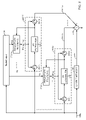
- FIG. 8 depicts an embodiment of a spur detector/suppressor 800 employing a plurality of the techniques disclosed herein.
- rotator-based techniques featuring rapid convergence time and enhanced frequency selectivity are provided for spur suppression. Also provided are techniques for searching for spur frequencies in a frequency spectrum, and for tracking such spur frequencies over time.
- CDMA code division multiple access
- TDMA time division multiple access
- FDMA frequency division multiple access
- OFDMA orthogonal frequency division multiple access
- OFDM orthogonal frequency division multiplexing
- SC-FDMA single-carrier frequency division multiple access
- a CDMA system may implement one or more radio access technologies such as cdma2000, Wideband-CDMA (W-CDMA), and so on.
- cdma2000 covers IS-95, IS-2000, and IS-856 standards.
- a TDMA system may implement Global System for Mobile Communications (GSM).
- GSM and W-CDMA are described in documents from a consortium named “3rd Generation Partnership Project” (3GPP).
- cdma2000 is described in documents from a consortium named “3rd Generation Partnership Project 2” (3GPP2).
- 3GPP and 3GPP2 documents are publicly available.
- An OFDMA system utilizes OFDM.
- An OFDM-based system transmits modulation symbols in the frequency domain whereas an SC-FDMA system transmits modulation symbols in the time domain.
- the techniques described herein may be used for any communication system in which a spur to be suppressed occupies only a portion of the desired signal bandwidth.
- the techniques are especially applicable for wideband communications systems such as, e.g., CDMA and OFDM-based systems, or systems whose performance is particularly sensitive to the presence of even relatively weak spurs, such as Global Positioning Systems (GPS) and Galileo.
- GPS Global Positioning Systems
- Galileo Galileo
- the techniques may be used for a wireless device as well as a base station in a wireless communication system.
- a base station is generally a fixed station that communicates with the wireless devices and may also be called a base transceiver system (BTS), a Node B, an access point, or some other terminology.
- BTS base transceiver system
- a wireless device may be fixed or mobile and may also be called a mobile station, a user equipment, a terminal, a subscriber unit, or some other terminology.
- a wireless device may be a cellular phone, a personal digital assistant (PDA), a wireless modem card, and so on.
- PDA personal digital assistant
- the techniques may also be used in wireless broadcast systems such as MediaFLO.
- FIG. 1 illustrates a frequency spectrum 100 a containing an instance of a desired signal A along with a single instance of a spur characterized by frequency ⁇ 1 .
- FIG. 1A illustrates another frequency spectrum 100 b containing multiple spurs at frequencies ⁇ 1 , ⁇ 2 , ⁇ 3 .
- the desired signal A is expected to have a bandwidth greater than the bandwidth of any single spur.
- the desired signal A may be a cdma2000 spread spectrum signal having a bandwidth of 1.23 MHz, while a spur may have a bandwidth on the order of a few kHz or less, or be a continuous-wave (CW) signal, e.g., a harmonic waveform having close to zero bandwidth.
- CW continuous-wave
- FIG. 2 depicts an embodiment of a spur suppressor 200 for suppressing a single spur from an input signal 200 a according to the present disclosure.
- the input signal 200 a may correspond to a signal having the spectrum 100 a shown in FIG. 1 .
- all signals referred to may generally be complex signals having both in-phase (I) and quadrature (Q) components.
- the computation blocks described, including rotators, subtractors, estimators, etc. may generally be capable of processing complex input and output signals.
- the input signal 200 a is shown rotated by a sinusoidal signal having complex frequency ⁇ using a rotator 210 .
- the rotator 210 is depicted with a counter-clockwise arrow, which is meant to indicate rotation, while the operation depicted with a clockwise arrow (e.g., corresponding to block 240 in FIG. 2 ) is meant to indicate de-rotation.
- a clockwise arrow e.g., corresponding to block 240 in FIG. 2
- the terms “rotation” and “de-rotation” denote multiplication by a complex sinusoid and multiplication by the complex conjugate of that complex sinusoid, respectively.
- rotation can refer to shifting a signal in frequency in either a positive direction or a negative direction depending on the context, while the term “de-rotation” used in conjunction with such a “rotation” will refer to shifting the signal in frequency in the opposite direction from the corresponding rotation. For example, if in one context, a “rotation” shifts a frequency in a negative direction, e.g., from a positive frequency ⁇ 1 to 0, then the corresponding “de-rotation” would shift a frequency in a positive direction, e.g., from 0 to a positive frequency ⁇ 1.
- a “rotation” shifts a frequency in a positive direction, e.g., from a negative frequency ⁇ 2 to 0, then the corresponding “de-rotation” would shift a frequency in a negative direction, e.g., from 0 to a negative frequency ⁇ 2. If the direction in which a rotation shifts a signal is unspecified, then the term will be understood to generally encompass any frequency shift, positive or negative.
- the complex frequency ⁇ used for rotation may be chosen to correspond to a spur frequency, e.g., the frequency ⁇ 1 associated with the spur shown in FIG. 1 .
- the spur frequency is positive, the operation of rotator 210 shifts the entire spectrum of the input signal 200 a in the negative direction such that the spur originally centered at ⁇ is now centered at DC, i.e., zero-frequency.
- the value of ⁇ may be derived using the spur searching and/or tracking algorithms described later hereinbelow with reference to FIGS. 4-6 .
- the value of ⁇ may be derived using any algorithm for identifying a frequency associated with a spur known to one of ordinary skill in the art.
- the value of ⁇ may be programmed with a fixed predetermined frequency, assuming the spur frequency is known a priori.
- any complex multiplier for multiplying two complex signals may be used, with the phase of the operands appropriately chosen depending on whether the operation is a rotation or de-rotation.
- the complex frequency rotation may be implemented using the CORDIC (coordinate rotation digital computer) algorithm well-known to one of ordinary skill in the art. These and other embodiments are contemplated to be within the scope of the present disclosure.
- the output signal 210 a of the rotator 210 is provided to a DC estimator 220 , which outputs a (complex) estimate ⁇ , or 220 a , of the DC value of the rotated signal 210 a .
- the rotated signal 210 a is expected to contain the spur corresponding to ⁇ centered at DC, and thus the DC estimator 220 is expected to estimate the value of the complex envelope of the spur originally at frequency ⁇ .
- a simple block averaging technique may be used, wherein the last N samples of the complex signal 210 a are averaged, and the result held constant as the signal 220 a for the subsequent N samples.
- a moving average filter may be used, wherein the last N samples of the complex signal 210 a are averaged sample by sample, and the result output as the signal 220 a .
- any low-pass filter with a low enough bandwidth may be used to obtain a DC estimate.
- Such low-pass filters may generally include finite-impulse response (FIR) filters or infinite-impulse response (IIR) filters.
- the last N samples of the complex signal 210 a may be averaged with an effective time constant, and the result output as the signal 220 a .
- FIG. 2 further shows that the DC estimate 220 a is subtracted from the rotated signal 210 a by subtractor 230 .
- the subtractor output 230 a is de-rotated by the frequency ⁇ using de-rotator 240 .
- the original input signal 200 a is recovered as processed signal 240 a , minus the components corresponding to spur frequency ⁇ as estimated by DC estimator 220 .
- FIG. 2A depicts an embodiment of the present disclosure wherein multiple instances of the spur suppressor 200 are concatenated in series as blocks 200 . 1 , 200 . 2 , . . . , 200 .N for suppressing a plurality of spurs ⁇ 1 through ⁇ N .
- Each of the spur suppressors 200 . 1 through 200 .N may be designed according to the principles described herein with reference to FIG. 2 .
- the DC estimate 220 a may generally be a delay present in the DC estimate 220 a computed for the signal 210 a .
- the DC estimator 220 employs the aforementioned block averaging scheme with block size N block
- the DC estimate 220 a subtracted from any single sample of 210 a by subtractor 230 will be computed from the previous block of N block samples, rather than the current sample of 210 a present at the input to subtractor 230 .
- This delay may result in an inaccuracy in the spur estimation, depending on the amount of delay between the current sample and the actual samples used to perform the DC estimation.
- the total length of a data burst is short relative to the delay, then by the time a DC estimate is calculated for a received signal of a data frame, the data frame may already have been terminated.
- data may be continuously received with a long enough duration such that the delay associated with the DC estimate is negligible.
- Examples of such systems include CDMA and W-CDMA.
- sample memory 250 may be provided as shown for the spur suppressor 201 of FIG. 2B .
- sample values 210 a are provided to a sample memory 250 , which is programmed to store and delay the sample values 210 a by a fixed delay.
- the sample memory 250 may store N block samples of the signal 210 a , and provide them to the subtractor 230 when the DC estimate 220 a associated with the stored N block samples is available. In this way, the subtraction of the DC estimate 220 a may be synchronized with the segment of signal 210 a used for the DC estimation.
- multiple instances of the spur suppressor 201 of FIG. 2B may also be concatenated in series (not shown) to suppress a plurality of spurs, in a manner analogous to the way in which multiple instances of the spur suppressor 200 of FIG. 2 are concatenated in series as shown in FIG. 2A .
- the embodiment described with reference to FIG. 2B may readily accommodate communication systems wherein data is received over limited bursts of time, e.g., a time division multiple access (TDMA) system such as GSM.
- TDMA time division multiple access
- GSM Global System for Mobile communications
- the complex rotator shown need not shift the signal containing the spur frequency to DC.
- the rotator may instead shift the signal containing the spur frequency to half the digital sampling frequency of the system.
- the spur component could be estimated using a digital ⁇ -frequency estimator, e.g., a module that multiplies successive samples by a sequence such as 1, ⁇ 1, 1, ⁇ 1, etc., before summing the multiplied samples to estimate the value of the component at digital frequency ⁇ (where 2 ⁇ would correspond to the digital sampling frequency).
- a digital ⁇ -frequency estimator e.g., a module that multiplies successive samples by a sequence such as 1, ⁇ 1, 1, ⁇ 1, etc., before summing the multiplied samples to estimate the value of the component at digital frequency ⁇ (where 2 ⁇ would correspond to the digital sampling frequency).
- the complex rotator may generally shift the signal containing the spur frequency to any intermediate frequency, and perform complex estimation of the frequency component at that intermediate frequency.
- the estimated frequency component may then be suppressed from the
- FIG. 3 depicts an embodiment of a spur suppressor 300 that subtracts an estimated spur from the input signal at the original spur frequency.
- the input signal 200 a is rotated by spur frequency ⁇ using rotator 310 , and the DC component ⁇ , or 320 a , of the signal 310 a is computed by DC estimator 320 .
- Signal 320 a is then de-rotated by frequency ⁇ using de-rotator 330 , before being subtracted from the original signal 200 a by subtractor 340 .
- spur suppressor 300 differs from that of spur suppressor 200 shown in FIG. 2 in that subtraction of the spur is done at the de-rotated (original) frequency rather than at the rotated frequency.
- sample memory 305 such as depicted in FIG. 3A may also be provided for the embodiment of FIG. 3 to account for delays in the system.
- FIG. 3B further depicts a parallel architecture to suppress multiple spurs ⁇ 1 through ⁇ N from an input signal 200 a .
- a spur estimation path labeled SP.n is provided for each of spurs ⁇ 1 through ⁇ N , wherein n is a spur index ranging from 1 to N.
- Each spur estimation path SP.n generates a signal 330 a .n that corresponds to a reconstructed, de-rotated version of spur ⁇ n .
- the DC estimates 320 a .n are all de-rotated by their respective spur frequencies con
- the spur estimates 330 a . 1 through 330 a .N may be simultaneously subtracted from the original (delayed) signal 305 a using subtractor 340 to generate the corrected signal 340 a.
- spur suppressor 300 may be concatenated in series as depicted in FIG. 2A for spur suppressor 200 , and such an embodiment is also contemplated to be within the scope of the present disclosure.
- FIG. 4 depicts an embodiment of a spur searcher.
- an input signal 400 a containing spurs of unknown frequency are provided to a single frequency spectral analyzer 400 .
- the single frequency spectral analyzer 400 calculates the power present at a given frequency ⁇ _search within the signal 400 a .
- the signal 400 a is rotated using a rotator 410 by a candidate frequency ⁇ _search, or 430 a , provided by a searcher algorithm block 430 .
- a DC estimator 420 estimates the DC component of the rotated signal 410 a .
- the DC estimate 420 a is then provided to a power calculation block 425 , which calculates the power 425 a of DC estimate 420 a .
- power is the metric used to estimate the strength of the candidate spurs in FIG. 4
- any other suitable metric may also be used, e.g., amplitude. Embodiments utilizing such other metrics are contemplated to be within the scope of the present disclosure.
- the power estimate 425 a is provided back to the searcher algorithm block 430 .
- the searcher algorithm block thereafter generates a new candidate frequency ⁇ _search, and again receives a corresponding power estimate 425 a from single frequency spectral analyzer 400 .
- the searcher algorithm block 430 may output frequencies ⁇ 1 through ⁇ N , or 430 a . 1 through 430 a .N, corresponding to the candidate frequencies deemed most likely to be spur frequencies. Such output frequencies may then be provided to a spur suppression module, such as previously described with reference to FIGS. 2-3 . In alternative embodiments, the output frequencies may generally be provided to any spur suppression module for spur suppression.
- a spur searcher may instead incorporate a Fast-Fourier Transform (FFT) module as an alternative to the rotator-based module 400 depicted in FIG. 4 .
- FFT Fast-Fourier Transform
- an FFT may be computed based on a segment of the input signal 400 a .
- the FFT may compute the amplitude or power present in the signal 400 a at a plurality of frequency points associated with the FFT. This spectral content information may then be provided to a suitable searcher algorithm block 430 to identify spurs.
- FIG. 5 depicts an embodiment of a frequency search algorithm that may be implemented as part of the searcher algorithm block 430 of FIG. 4 .
- a plurality of candidate frequencies ⁇ _cand(i) to be evaluated is chosen at step 500 , wherein i is an index ranging from 1 to a maximum I.
- the candidate frequencies ⁇ _cand(i) may be chosen to uniformly span the total bandwidth of a desired signal.
- the index i is initialized to 1.
- ⁇ _search is set equal to ⁇ _cand(i).
- ⁇ _search is supplied to a spectral analyzer, such as described with reference to block 400 in FIG. 4 .
- the measured power P(i) corresponding to ⁇ _cand(i) is provided to a candidate selection scheme 530 .
- Candidate selection scheme 530 outputs a list of spur frequencies ⁇ 1 through ⁇ N according to a predetermined algorithm, an embodiment of which is described in FIG. 6 .
- the index i is evaluated against the maximum index I at step 520 , which determines whether i is to be incremented to evaluate the next frequency ⁇ _cand(i+1), or whether i is to be looped back to step 505 .
- FIG. 6 illustrates the functionality of a candidate selection scheme 530 .
- the selection scheme may store each candidate frequency ⁇ _cand(i) and corresponding P(i) in a table 600 .
- Candidate selection block 605 may select a subset N determined to be spur frequencies from the set of candidate frequencies I, the subset N including spur frequencies ⁇ 1 through ⁇ N .
- candidate selection block 605 may select a subset N determined to be spur frequencies from the set of candidate frequencies I, the subset N including spur frequencies ⁇ 1 through ⁇ N .
- a predetermined threshold Thresh are declared spur frequencies. Note the present disclosure is not limited to any particular embodiment of candidate selection block 605 , and one of ordinary skill in the art will appreciate that other embodiments may employ alternative criteria and techniques to select and/or rank candidate frequencies for further processing.
- FIGS. 5 and 6 Note the embodiment of the searcher algorithm depicted in FIGS. 5 and 6 is provided for illustration only. One of ordinary skill in the art may readily derive other techniques for sweeping through, identifying, and/or ranking preferred spur frequencies given an arbitrary list of candidate frequencies and corresponding measured amplitude or power levels.
- searcher architecture and algorithm described with reference to FIGS. 4 and 5 correspond to a serial searching architecture, i.e., the power corresponding to each possible candidate frequency is evaluated one after another, in seriatim.
- the single frequency spectral analyzer may be substituted with a multiple frequency spectral analyzer to simultaneously measure the power of a plurality of frequencies on each run.
- Such a multiple frequency spectral analyzer may include, e.g., multiple instances of the rotator 410 , DC estimator 420 , and power calculator 425 coupled in parallel.
- One of ordinary skill in the art may make appropriate modifications to the searcher algorithm of FIG. 5 to accommodate such an architecture.
- FIG. 7 depicts an embodiment of a spur frequency tracking scheme according to the present disclosure.
- a spur suppressor 700 is provided to suppress spurs of frequency ⁇ n — track from an input signal 700 a .
- the architecture of spur suppressor 700 corresponds to that of the embodiment shown in FIG. 3A .
- spur suppressors employing any of the architectures described hereinabove may be used.
- the actual value of the frequency ⁇ n — track supplied to rotator 710 and de-rotator 730 of spur suppressor 700 is generated by a frequency tracking block 770 , whose operation is described hereinbelow.
- Frequency tracking block 770 inputs from DC estimator 720 a complex DC estimate 720 a having both in-phase (I) and quadrature (Q) components.
- the signal 720 a is alternatively denoted as ⁇ n (t), wherein n is an index to the spur, and t is the time at which the signal 720 a is sampled.
- Delay block 772 delays signal 720 a by a time delay ⁇ t to generate an output ⁇ n (t ⁇ t), or 772 a .
- CPD cross-product detector
- the signal 774 a is filtered by an infinite impulse response (IIR) filter 776 .
- the output 776 a of the IIR filter 776 may be further multiplied by a scaling gain 778 to produce a signal 778 a .
- the signal 778 a is subtracted from a frequency ⁇ n by subtractor 780 .
- the frequency ⁇ n may be a coarse spur frequency estimate supplied from a searcher such as depicted in FIGS. 4-6 .
- the output 780 a of the subtractor 780 is supplied to the rotators 710 and 740 in spur suppressor 700 as the tracked spur frequency ⁇ n — track.
- the DC estimator 420 of the searcher shown in FIG. 4 may employ a block-averaging filter with a block size N block much smaller than a block size N block employed for the DC estimator 720 in the frequency tracking loop shown in FIG. 7 . This may be done so that the frequency resolution for the searcher may be coarser than the frequency resolution for the frequency tracking loop, to enable faster searching times.
- tracking block 770 may be provided for each spur suppressor, to track each of the plurality of spurs detected (by, e.g., a searcher) in the signal 770 a.
- FIG. 8 depicts an embodiment of a spur detector/suppressor 800 employing a plurality of the techniques disclosed hereinabove.
- the embodiment in FIG. 8 employs a plurality of spur suppressors 800 . 1 through 800 .N for suppressing spurs from an input signal 800 a , coupled in parallel as described with reference to FIG. 3B above.
- a sample memory 805 is provided to delay the incoming samples 800 a so that they are synchronized with the spur estimates.
- a searcher 400 identifies a plurality of spur frequencies ⁇ 1 through ⁇ N with coarse precision, and provides these frequency estimates to the tracking blocks 770 . 1 through 770 .N.
- Each tracking block 770 . n is configured to dynamically track each spur frequency, as described with reference to FIG. 7 .
- the outputs of the spur suppressors 830 . 1 a through 803 .Na are subtracted from the delayed signal 805 a by subtractor 840 .
- the operation of the embodiment shown in FIG. 8 will be clear to one of ordinary skill in the art. Note the embodiment is shown for illustrative purposes only, and is not meant to limit the scope of the present disclosure to the particular embodiment depicted in FIG. 8 .
- the functions described may be implemented in hardware, software, firmware, or any combination thereof. If implemented in software, the functions may be stored on or transmitted over as one or more instructions or code on a computer-readable medium.
- Computer-readable media includes both computer storage media and communication media including any medium that facilitates transfer of a computer program from one place to another.
- a storage media may be any available media that can be accessed by a computer.
- such computer-readable media can comprise RAM, ROM, EEPROM, CD-ROM or other optical disk storage, magnetic disk storage or other magnetic storage devices, or any other medium that can be used to carry or store desired program code in the form of instructions or data structures and that can be accessed by a computer.
- any connection is properly termed a computer-readable medium.
- the software is transmitted from a website, server, or other remote source using a coaxial cable, fiber optic cable, twisted pair, digital subscriber line (DSL), or wireless technologies such as infrared, radio, and microwave
- DSL digital subscriber line
- wireless technologies such as infrared, radio, and microwave
- Disk and disc includes compact disc (CD), laser disc, optical disc, digital versatile disc (DVD), floppy disk and blu-ray disc where disks usually reproduce data magnetically, while discs reproduce data optically with lasers. Combinations of the above should also be included within the scope of computer-readable media.
- the instructions or code associated with a computer-readable medium of the computer program product may be executed by a computer, e.g., by one or more processors, such as one or more digital signal processors (DSPs), general purpose microprocessors, ASICs, FPGAs, or other equivalent integrated or discrete logic circuitry.
- processors such as one or more digital signal processors (DSPs), general purpose microprocessors, ASICs, FPGAs, or other equivalent integrated or discrete logic circuitry.
Landscapes
- Engineering & Computer Science (AREA)
- Computer Networks & Wireless Communication (AREA)
- Signal Processing (AREA)
- Digital Transmission Methods That Use Modulated Carrier Waves (AREA)
- Measuring Frequencies, Analyzing Spectra (AREA)
- Noise Elimination (AREA)
- Radar Systems Or Details Thereof (AREA)
- Manipulation Of Pulses (AREA)
Abstract
Description
y=α n(t)I*αn(t−Δt)Q−αn(t)Q*αn(t−Δt)I;
wherein XI and XQ represent the I and Q components, respectively, of a complex signal X.
y IIR(p)=βx IIR(p)+(1−β)y IIR(p−1);
wherein p is a discrete time index, xIIR is the IIR filter input, yIIR is the IIR filter output, and β is a loop gain constant (less than 1) that can be adjusted to vary the response time of the tracking loop to trade off tracking speed for accuracy.
Claims (28)
Priority Applications (7)
| Application Number | Priority Date | Filing Date | Title |
|---|---|---|---|
| US12/116,539 US8254855B2 (en) | 2008-05-07 | 2008-05-07 | Frequency spur detection and suppression |
| PCT/US2009/043037 WO2009137619A2 (en) | 2008-05-07 | 2009-05-06 | Frequency spur detection and suppression |
| CN2009801163747A CN102017430A (en) | 2008-05-07 | 2009-05-06 | Frequency spur detection and suppression |
| EP09743605A EP2274834A2 (en) | 2008-05-07 | 2009-05-06 | Frequency spur detection and suppression |
| JP2011508641A JP2011520392A (en) | 2008-05-07 | 2009-05-06 | Frequency spurious detection and suppression |
| KR1020107027456A KR20110004901A (en) | 2008-05-07 | 2009-05-06 | Frequency spur detection and suppression |
| TW098115188A TW200952357A (en) | 2008-05-07 | 2009-05-07 | Frequency spur detection and suppression |
Applications Claiming Priority (1)
| Application Number | Priority Date | Filing Date | Title |
|---|---|---|---|
| US12/116,539 US8254855B2 (en) | 2008-05-07 | 2008-05-07 | Frequency spur detection and suppression |
Publications (2)
| Publication Number | Publication Date |
|---|---|
| US20090279591A1 US20090279591A1 (en) | 2009-11-12 |
| US8254855B2 true US8254855B2 (en) | 2012-08-28 |
Family
ID=40886140
Family Applications (1)
| Application Number | Title | Priority Date | Filing Date |
|---|---|---|---|
| US12/116,539 Expired - Fee Related US8254855B2 (en) | 2008-05-07 | 2008-05-07 | Frequency spur detection and suppression |
Country Status (7)
| Country | Link |
|---|---|
| US (1) | US8254855B2 (en) |
| EP (1) | EP2274834A2 (en) |
| JP (1) | JP2011520392A (en) |
| KR (1) | KR20110004901A (en) |
| CN (1) | CN102017430A (en) |
| TW (1) | TW200952357A (en) |
| WO (1) | WO2009137619A2 (en) |
Cited By (1)
| Publication number | Priority date | Publication date | Assignee | Title |
|---|---|---|---|---|
| US20130266093A1 (en) * | 2010-12-22 | 2013-10-10 | Telefonaktiebolaget L M Ericsson (Publ) | Methods and Receiver for Positioning of Clock Related Spurious Signals |
Families Citing this family (11)
| Publication number | Priority date | Publication date | Assignee | Title |
|---|---|---|---|---|
| US20070202830A1 (en) * | 2006-02-24 | 2007-08-30 | Texas Instruments Incorporated | Spurious tone suppressor and method of operation thereof |
| EP2398151A1 (en) * | 2010-06-21 | 2011-12-21 | Nxp B.V. | Radio receiver apparatus and method for operating the apparatus |
| GB201114079D0 (en) | 2011-06-13 | 2011-09-28 | Neul Ltd | Mobile base station |
| GB2491908B (en) * | 2011-06-13 | 2013-07-24 | Neul Ltd | Calibration mode |
| CN105702601B (en) | 2011-06-23 | 2020-02-07 | 布鲁克斯Ccs有限公司 | Cleaning system and method |
| JP5716617B2 (en) * | 2011-09-12 | 2015-05-13 | 富士通株式会社 | Signal processing circuit, signal processing method, and reception system |
| JP6085976B2 (en) * | 2013-01-25 | 2017-03-01 | 富士通株式会社 | Signal processing circuit and signal processing method |
| CN107547087B (en) * | 2016-06-29 | 2020-11-24 | 澜起科技股份有限公司 | Circuit and method for reducing mismatch of synthesized clock signals |
| KR101755438B1 (en) * | 2016-07-08 | 2017-07-10 | 피앤피넷 주식회사 | Cancellation apparatus of spurious signal and cancellation method therefor |
| CN110730013B (en) * | 2019-09-25 | 2021-09-17 | 维沃移动通信有限公司 | Method for improving transmission stray and mobile terminal |
| US11469784B2 (en) * | 2019-10-03 | 2022-10-11 | Texas Instruments Incorporated | Spur estimating receiver system |
Citations (11)
| Publication number | Priority date | Publication date | Assignee | Title |
|---|---|---|---|---|
| US4453137A (en) | 1982-02-05 | 1984-06-05 | The United States Of America As Represented By The Secretary Of The Army | Signal processor for plural frequency detection and tracking over predetermined range of frequencies |
| DE4220228A1 (en) | 1992-06-20 | 1994-04-07 | Blaupunkt Werke Gmbh | Narrow band interference suppression circuit with controlled oscillator - offsets intermediate-frequency signals by amt. dependent on frequency of interfering signal before application to notch filter |
| US5410750A (en) | 1992-02-24 | 1995-04-25 | Raytheon Company | Interference suppressor for a radio receiver |
| WO2000046929A1 (en) | 1999-02-02 | 2000-08-10 | Lockheed Martin Canada | Maintaining performance quality of broadband system in the presence of narrow band interference |
| US20010040932A1 (en) * | 1999-10-22 | 2001-11-15 | Bjorn Lindquist | Communications terminal having a receiver and method for removing known interferers from a digitized intermediate frequency signal |
| US20040057503A1 (en) | 2002-09-24 | 2004-03-25 | Motorola, Inc. | Method and apparatus for processing a composite signal including a desired spread spectrum signal and an undesired narrower-band interfering signal |
| US6718166B2 (en) | 2002-05-17 | 2004-04-06 | Illinois Superconductor Corporation, Inc. | Multiple carrier adaptive notch filter |
| US6807222B1 (en) | 1998-01-22 | 2004-10-19 | British Telecommunications Public Limited Company | Receiving spread spectrum signals with narrowband interference |
| US20050059366A1 (en) * | 2003-09-16 | 2005-03-17 | Atheros Communications, Inc. | Spur mitigation techniques |
| US7194050B2 (en) | 2002-09-30 | 2007-03-20 | Nortel Networks Limited | Reducing narrowband interference in a wideband signal |
| US20070153878A1 (en) | 2006-01-04 | 2007-07-05 | Filipovic Daniel F | Spur suppression for a receiver in a wireless communication system |
Family Cites Families (2)
| Publication number | Priority date | Publication date | Assignee | Title |
|---|---|---|---|---|
| JP3686794B2 (en) * | 1999-07-29 | 2005-08-24 | アイコム株式会社 | Signal removal apparatus, signal removal method, and recording medium |
| JP2005064846A (en) * | 2003-08-12 | 2005-03-10 | Nippon Hoso Kyokai <Nhk> | Interference eliminator |
-
2008
- 2008-05-07 US US12/116,539 patent/US8254855B2/en not_active Expired - Fee Related
-
2009
- 2009-05-06 WO PCT/US2009/043037 patent/WO2009137619A2/en active Application Filing
- 2009-05-06 KR KR1020107027456A patent/KR20110004901A/en not_active Application Discontinuation
- 2009-05-06 EP EP09743605A patent/EP2274834A2/en not_active Withdrawn
- 2009-05-06 JP JP2011508641A patent/JP2011520392A/en active Pending
- 2009-05-06 CN CN2009801163747A patent/CN102017430A/en active Pending
- 2009-05-07 TW TW098115188A patent/TW200952357A/en unknown
Patent Citations (11)
| Publication number | Priority date | Publication date | Assignee | Title |
|---|---|---|---|---|
| US4453137A (en) | 1982-02-05 | 1984-06-05 | The United States Of America As Represented By The Secretary Of The Army | Signal processor for plural frequency detection and tracking over predetermined range of frequencies |
| US5410750A (en) | 1992-02-24 | 1995-04-25 | Raytheon Company | Interference suppressor for a radio receiver |
| DE4220228A1 (en) | 1992-06-20 | 1994-04-07 | Blaupunkt Werke Gmbh | Narrow band interference suppression circuit with controlled oscillator - offsets intermediate-frequency signals by amt. dependent on frequency of interfering signal before application to notch filter |
| US6807222B1 (en) | 1998-01-22 | 2004-10-19 | British Telecommunications Public Limited Company | Receiving spread spectrum signals with narrowband interference |
| WO2000046929A1 (en) | 1999-02-02 | 2000-08-10 | Lockheed Martin Canada | Maintaining performance quality of broadband system in the presence of narrow band interference |
| US20010040932A1 (en) * | 1999-10-22 | 2001-11-15 | Bjorn Lindquist | Communications terminal having a receiver and method for removing known interferers from a digitized intermediate frequency signal |
| US6718166B2 (en) | 2002-05-17 | 2004-04-06 | Illinois Superconductor Corporation, Inc. | Multiple carrier adaptive notch filter |
| US20040057503A1 (en) | 2002-09-24 | 2004-03-25 | Motorola, Inc. | Method and apparatus for processing a composite signal including a desired spread spectrum signal and an undesired narrower-band interfering signal |
| US7194050B2 (en) | 2002-09-30 | 2007-03-20 | Nortel Networks Limited | Reducing narrowband interference in a wideband signal |
| US20050059366A1 (en) * | 2003-09-16 | 2005-03-17 | Atheros Communications, Inc. | Spur mitigation techniques |
| US20070153878A1 (en) | 2006-01-04 | 2007-07-05 | Filipovic Daniel F | Spur suppression for a receiver in a wireless communication system |
Non-Patent Citations (1)
| Title |
|---|
| International Search Report and Written Opinion-PCT/US2009/043037, International Search Authority-European Patent Office-Nov. 3, 2009. |
Cited By (2)
| Publication number | Priority date | Publication date | Assignee | Title |
|---|---|---|---|---|
| US20130266093A1 (en) * | 2010-12-22 | 2013-10-10 | Telefonaktiebolaget L M Ericsson (Publ) | Methods and Receiver for Positioning of Clock Related Spurious Signals |
| US9391823B2 (en) * | 2010-12-22 | 2016-07-12 | Telefonaktiebolaget Lm Ericsson (Publ) | Methods and receiver for positioning of clock related spurious signals |
Also Published As
| Publication number | Publication date |
|---|---|
| WO2009137619A2 (en) | 2009-11-12 |
| KR20110004901A (en) | 2011-01-14 |
| JP2011520392A (en) | 2011-07-14 |
| US20090279591A1 (en) | 2009-11-12 |
| TW200952357A (en) | 2009-12-16 |
| CN102017430A (en) | 2011-04-13 |
| EP2274834A2 (en) | 2011-01-19 |
| WO2009137619A3 (en) | 2009-12-30 |
Similar Documents
| Publication | Publication Date | Title |
|---|---|---|
| US8254855B2 (en) | Frequency spur detection and suppression | |
| US9118401B1 (en) | Method of adaptive interference mitigation in wide band spectrum | |
| Savasta et al. | Interference mitigation in GNSS receivers by a time-frequency approach | |
| JP4095249B2 (en) | Frequency acquisition tracking method and apparatus for DS-SSCDMA receiver | |
| US20170234987A1 (en) | Method and apparatus for joint data-pilot tracking of navigation signal | |
| US10855494B2 (en) | Transmitter and receiver and corresponding methods | |
| US7620125B1 (en) | Frequency estimation apparatus and related method | |
| WO2006111275A2 (en) | Initial parameter estimation in ofdm systems | |
| US8077820B2 (en) | Detection of frequency correction bursts and the like | |
| JP2013153440A (en) | Communication channel estimation | |
| Tamazin et al. | Robust fine acquisition algorithm for GPS receiver with limited resources | |
| US11894966B2 (en) | Method and apparatus for estimating frequency offset, electronic device and computer-readable medium | |
| US7643541B2 (en) | Device and method for determining a correlation value | |
| Borio et al. | A non-coherent architecture for GNSS digital tracking loops | |
| US20050041725A1 (en) | Receiver of an ultra wide band signal and associated reception method | |
| US9031124B1 (en) | Scheme for generating hypothesis and estimating a carrier frequency offset in a receiver | |
| Ren et al. | CW interference mitigation in GNSS receiver based on frequency-locked loop | |
| CN111404857A (en) | Carrier synchronization method, device, storage medium and processor | |
| Wang et al. | Performance comparison of code discriminators in the presence of CW interference | |
| JP4335125B2 (en) | Timing synchronization circuit | |
| US20240219579A1 (en) | Method, device and system of multi-carrier constant envelope gnss waveforms compatible with existing user equipment | |
| KR100869500B1 (en) | Apparatus for correcting frequency error in communication system | |
| KR102574425B1 (en) | Apparatus for receiving Orthogonal Frequency Division Multiplexing signal based on baseband and Method for estimating error of sample clock | |
| CN108508460A (en) | A kind of GNSS signal carrier wave tracing method and device | |
| Li et al. | Preliminary insights on fast GNSS signal capture using SFT and FFT frequency shift |
Legal Events
| Date | Code | Title | Description |
|---|---|---|---|
| AS | Assignment |
Owner name: QUALCOMM INCORPORATED, CALIFORNIA Free format text: ASSIGNMENT OF ASSIGNORS INTEREST;ASSIGNORS:FILIPOVIC, DANIEL FRED;O'SHEA, HELENA DEIRDRE;KOMNINAKIS, CHRISTOS;AND OTHERS;REEL/FRAME:020922/0303;SIGNING DATES FROM 20080222 TO 20080416 Owner name: QUALCOMM INCORPORATED, CALIFORNIA Free format text: ASSIGNMENT OF ASSIGNORS INTEREST;ASSIGNORS:FILIPOVIC, DANIEL FRED;O'SHEA, HELENA DEIRDRE;KOMNINAKIS, CHRISTOS;AND OTHERS;SIGNING DATES FROM 20080222 TO 20080416;REEL/FRAME:020922/0303 |
|
| ZAAA | Notice of allowance and fees due |
Free format text: ORIGINAL CODE: NOA |
|
| ZAAB | Notice of allowance mailed |
Free format text: ORIGINAL CODE: MN/=. |
|
| AS | Assignment |
Owner name: QUALCOMM INCORPORATED, CALIFORNIA Free format text: CORRECTIVE ASSIGNMENT TO CORRECT THE EXECUTION DATE FOR INVENTOR DANIEL FILIPOVIC SHOULD BE 04/22/2008 PREVIOUSLY RECORDED ON REEL 020922 FRAME 0303. ASSIGNOR(S) HEREBY CONFIRMS THE ASSIGNMENT OF APPL NO. 12/116,539 TO QUALCOMM INCORPORATED;ASSIGNORS:FILIPOVIC, DANIEL FRED;O'SHEA, HELENA DEIRDRE;KOMNINAKIS, CHRISTOS;AND OTHERS;SIGNING DATES FROM 20080415 TO 20080422;REEL/FRAME:028002/0462 |
|
| ZAAA | Notice of allowance and fees due |
Free format text: ORIGINAL CODE: NOA |
|
| ZAAB | Notice of allowance mailed |
Free format text: ORIGINAL CODE: MN/=. |
|
| STCF | Information on status: patent grant |
Free format text: PATENTED CASE |
|
| FPAY | Fee payment |
Year of fee payment: 4 |
|
| MAFP | Maintenance fee payment |
Free format text: PAYMENT OF MAINTENANCE FEE, 8TH YEAR, LARGE ENTITY (ORIGINAL EVENT CODE: M1552); ENTITY STATUS OF PATENT OWNER: LARGE ENTITY Year of fee payment: 8 |
|
| FEPP | Fee payment procedure |
Free format text: MAINTENANCE FEE REMINDER MAILED (ORIGINAL EVENT CODE: REM.); ENTITY STATUS OF PATENT OWNER: LARGE ENTITY |
|
| LAPS | Lapse for failure to pay maintenance fees |
Free format text: PATENT EXPIRED FOR FAILURE TO PAY MAINTENANCE FEES (ORIGINAL EVENT CODE: EXP.); ENTITY STATUS OF PATENT OWNER: LARGE ENTITY |
|
| STCH | Information on status: patent discontinuation |
Free format text: PATENT EXPIRED DUE TO NONPAYMENT OF MAINTENANCE FEES UNDER 37 CFR 1.362 |