US8241726B2 - Impact absorbing safety matting system with elastomeric sub-surface structure - Google Patents
Impact absorbing safety matting system with elastomeric sub-surface structure Download PDFInfo
- Publication number
- US8241726B2 US8241726B2 US12/543,282 US54328209A US8241726B2 US 8241726 B2 US8241726 B2 US 8241726B2 US 54328209 A US54328209 A US 54328209A US 8241726 B2 US8241726 B2 US 8241726B2
- Authority
- US
- United States
- Prior art keywords
- mat
- column
- impact
- mats
- resilient
- Prior art date
- Legal status (The legal status is an assumption and is not a legal conclusion. Google has not performed a legal analysis and makes no representation as to the accuracy of the status listed.)
- Expired - Fee Related, expires
Links
- 239000011800 void material Substances 0.000 claims abstract description 21
- 230000008093 supporting effect Effects 0.000 claims abstract description 10
- 230000002093 peripheral effect Effects 0.000 claims description 2
- 210000004872 soft tissue Anatomy 0.000 description 38
- 210000002683 foot Anatomy 0.000 description 34
- 239000000463 material Substances 0.000 description 28
- 206010016256 fatigue Diseases 0.000 description 25
- 230000002929 anti-fatigue Effects 0.000 description 19
- 230000000694 effects Effects 0.000 description 19
- 238000007906 compression Methods 0.000 description 18
- 230000006835 compression Effects 0.000 description 18
- 238000006073 displacement reaction Methods 0.000 description 18
- 239000006260 foam Substances 0.000 description 16
- 238000012360 testing method Methods 0.000 description 15
- 230000001965 increasing effect Effects 0.000 description 12
- 239000010410 layer Substances 0.000 description 12
- 230000035939 shock Effects 0.000 description 12
- 210000002414 leg Anatomy 0.000 description 11
- 230000006378 damage Effects 0.000 description 9
- 238000009408 flooring Methods 0.000 description 9
- 238000005304 joining Methods 0.000 description 9
- 230000008447 perception Effects 0.000 description 9
- 229920001971 elastomer Polymers 0.000 description 8
- 230000006870 function Effects 0.000 description 8
- 239000002344 surface layer Substances 0.000 description 8
- 208000016255 tiredness Diseases 0.000 description 8
- 230000003867 tiredness Effects 0.000 description 8
- 208000027418 Wounds and injury Diseases 0.000 description 7
- 208000014674 injury Diseases 0.000 description 7
- 238000004458 analytical method Methods 0.000 description 6
- 210000004027 cell Anatomy 0.000 description 6
- 238000000034 method Methods 0.000 description 6
- 230000009467 reduction Effects 0.000 description 6
- 206010020100 Hip fracture Diseases 0.000 description 5
- 238000013016 damping Methods 0.000 description 5
- 230000033001 locomotion Effects 0.000 description 5
- 230000004044 response Effects 0.000 description 5
- 230000008961 swelling Effects 0.000 description 5
- 101100495270 Caenorhabditis elegans cdc-26 gene Proteins 0.000 description 4
- 206010017076 Fracture Diseases 0.000 description 4
- 238000010586 diagram Methods 0.000 description 4
- 230000003116 impacting effect Effects 0.000 description 4
- 238000011160 research Methods 0.000 description 4
- 238000004088 simulation Methods 0.000 description 4
- 125000006850 spacer group Chemical group 0.000 description 4
- 238000013334 tissue model Methods 0.000 description 4
- 208000010392 Bone Fractures Diseases 0.000 description 3
- 238000010521 absorption reaction Methods 0.000 description 3
- 238000004364 calculation method Methods 0.000 description 3
- 239000013536 elastomeric material Substances 0.000 description 3
- 239000003292 glue Substances 0.000 description 3
- 239000007788 liquid Substances 0.000 description 3
- 238000005259 measurement Methods 0.000 description 3
- 210000003205 muscle Anatomy 0.000 description 3
- 230000035515 penetration Effects 0.000 description 3
- 230000001144 postural effect Effects 0.000 description 3
- 230000001681 protective effect Effects 0.000 description 3
- ACWBQPMHZXGDFX-QFIPXVFZSA-N valsartan Chemical compound C1=CC(CN(C(=O)CCCC)[C@@H](C(C)C)C(O)=O)=CC=C1C1=CC=CC=C1C1=NN=NN1 ACWBQPMHZXGDFX-QFIPXVFZSA-N 0.000 description 3
- 238000005303 weighing Methods 0.000 description 3
- 206010033425 Pain in extremity Diseases 0.000 description 2
- 238000004026 adhesive bonding Methods 0.000 description 2
- 238000013459 approach Methods 0.000 description 2
- 230000000386 athletic effect Effects 0.000 description 2
- 230000008901 benefit Effects 0.000 description 2
- 239000008280 blood Substances 0.000 description 2
- 210000004369 blood Anatomy 0.000 description 2
- 230000002860 competitive effect Effects 0.000 description 2
- 230000009514 concussion Effects 0.000 description 2
- 238000000280 densification Methods 0.000 description 2
- 239000000806 elastomer Substances 0.000 description 2
- 230000007246 mechanism Effects 0.000 description 2
- 230000002035 prolonged effect Effects 0.000 description 2
- 230000003938 response to stress Effects 0.000 description 2
- 230000000284 resting effect Effects 0.000 description 2
- 206010063746 Accidental death Diseases 0.000 description 1
- 238000012935 Averaging Methods 0.000 description 1
- 208000008035 Back Pain Diseases 0.000 description 1
- 102100040428 Chitobiosyldiphosphodolichol beta-mannosyltransferase Human genes 0.000 description 1
- 229920002943 EPDM rubber Polymers 0.000 description 1
- JOYRKODLDBILNP-UHFFFAOYSA-N Ethyl urethane Chemical compound CCOC(N)=O JOYRKODLDBILNP-UHFFFAOYSA-N 0.000 description 1
- 244000043261 Hevea brasiliensis Species 0.000 description 1
- 206010061224 Limb discomfort Diseases 0.000 description 1
- 206010030113 Oedema Diseases 0.000 description 1
- 230000003213 activating effect Effects 0.000 description 1
- 230000004913 activation Effects 0.000 description 1
- 210000003423 ankle Anatomy 0.000 description 1
- 230000017531 blood circulation Effects 0.000 description 1
- 210000000988 bone and bone Anatomy 0.000 description 1
- 230000008859 change Effects 0.000 description 1
- 230000004087 circulation Effects 0.000 description 1
- 238000004140 cleaning Methods 0.000 description 1
- 238000000576 coating method Methods 0.000 description 1
- 238000005056 compaction Methods 0.000 description 1
- 238000012669 compression test Methods 0.000 description 1
- 230000002153 concerted effect Effects 0.000 description 1
- 238000010276 construction Methods 0.000 description 1
- 238000007796 conventional method Methods 0.000 description 1
- 101150047356 dec-1 gene Proteins 0.000 description 1
- 238000004134 energy conservation Methods 0.000 description 1
- 238000005516 engineering process Methods 0.000 description 1
- 238000002474 experimental method Methods 0.000 description 1
- 235000013410 fast food Nutrition 0.000 description 1
- 230000002349 favourable effect Effects 0.000 description 1
- 210000002436 femur neck Anatomy 0.000 description 1
- 210000000497 foam cell Anatomy 0.000 description 1
- 238000009472 formulation Methods 0.000 description 1
- 230000036541 health Effects 0.000 description 1
- 238000012623 in vivo measurement Methods 0.000 description 1
- 230000001939 inductive effect Effects 0.000 description 1
- 230000000266 injurious effect Effects 0.000 description 1
- 229910052500 inorganic mineral Inorganic materials 0.000 description 1
- 238000009434 installation Methods 0.000 description 1
- 230000010354 integration Effects 0.000 description 1
- 230000001788 irregular Effects 0.000 description 1
- 238000012886 linear function Methods 0.000 description 1
- 238000004519 manufacturing process Methods 0.000 description 1
- 239000011707 mineral Substances 0.000 description 1
- 239000000203 mixture Substances 0.000 description 1
- 238000012986 modification Methods 0.000 description 1
- 230000004048 modification Effects 0.000 description 1
- 238000000465 moulding Methods 0.000 description 1
- 210000001087 myotubule Anatomy 0.000 description 1
- 229920003052 natural elastomer Polymers 0.000 description 1
- 229920001194 natural rubber Polymers 0.000 description 1
- 238000012856 packing Methods 0.000 description 1
- 238000000554 physical therapy Methods 0.000 description 1
- 238000011176 pooling Methods 0.000 description 1
- 238000005086 pumping Methods 0.000 description 1
- 230000002829 reductive effect Effects 0.000 description 1
- 238000012552 review Methods 0.000 description 1
- 238000005096 rolling process Methods 0.000 description 1
- 210000003625 skull Anatomy 0.000 description 1
- 239000007787 solid Substances 0.000 description 1
- 238000004154 testing of material Methods 0.000 description 1
- 230000008719 thickening Effects 0.000 description 1
- 150000003673 urethanes Chemical class 0.000 description 1
- 125000000391 vinyl group Chemical group [H]C([*])=C([H])[H] 0.000 description 1
- 229920002554 vinyl polymer Polymers 0.000 description 1
- 239000004636 vulcanized rubber Substances 0.000 description 1
- 230000003245 working effect Effects 0.000 description 1
Images


Classifications
-
- E—FIXED CONSTRUCTIONS
- E01—CONSTRUCTION OF ROADS, RAILWAYS, OR BRIDGES
- E01C—CONSTRUCTION OF, OR SURFACES FOR, ROADS, SPORTS GROUNDS, OR THE LIKE; MACHINES OR AUXILIARY TOOLS FOR CONSTRUCTION OR REPAIR
- E01C13/00—Pavings or foundations specially adapted for playgrounds or sports grounds; Drainage, irrigation or heating of sports grounds
- E01C13/02—Foundations, e.g. with drainage or heating arrangements
-
- A—HUMAN NECESSITIES
- A47—FURNITURE; DOMESTIC ARTICLES OR APPLIANCES; COFFEE MILLS; SPICE MILLS; SUCTION CLEANERS IN GENERAL
- A47G—HOUSEHOLD OR TABLE EQUIPMENT
- A47G27/00—Floor fabrics; Fastenings therefor
- A47G27/02—Carpets; Stair runners; Bedside rugs; Foot mats
- A47G27/0212—Carpets; Stair runners; Bedside rugs; Foot mats to support or cushion
- A47G27/0231—Carpets; Stair runners; Bedside rugs; Foot mats to support or cushion for fighting fatigue
-
- B—PERFORMING OPERATIONS; TRANSPORTING
- B32—LAYERED PRODUCTS
- B32B—LAYERED PRODUCTS, i.e. PRODUCTS BUILT-UP OF STRATA OF FLAT OR NON-FLAT, e.g. CELLULAR OR HONEYCOMB, FORM
- B32B25/00—Layered products comprising a layer of natural or synthetic rubber
- B32B25/04—Layered products comprising a layer of natural or synthetic rubber comprising rubber as the main or only constituent of a layer, which is next to another layer of the same or of a different material
- B32B25/08—Layered products comprising a layer of natural or synthetic rubber comprising rubber as the main or only constituent of a layer, which is next to another layer of the same or of a different material of synthetic resin
-
- E—FIXED CONSTRUCTIONS
- E04—BUILDING
- E04F—FINISHING WORK ON BUILDINGS, e.g. STAIRS, FLOORS
- E04F15/00—Flooring
- E04F15/02—Flooring or floor layers composed of a number of similar elements
- E04F15/10—Flooring or floor layers composed of a number of similar elements of other materials, e.g. fibrous or chipped materials, organic plastics, magnesite tiles, hardboard, or with a top layer of other materials
- E04F15/105—Flooring or floor layers composed of a number of similar elements of other materials, e.g. fibrous or chipped materials, organic plastics, magnesite tiles, hardboard, or with a top layer of other materials of organic plastics with or without reinforcements or filling materials
-
- E—FIXED CONSTRUCTIONS
- E04—BUILDING
- E04F—FINISHING WORK ON BUILDINGS, e.g. STAIRS, FLOORS
- E04F15/00—Flooring
- E04F15/18—Separately-laid insulating layers; Other additional insulating measures; Floating floors
- E04F15/185—Underlayers in the form of studded or ribbed plates
-
- E—FIXED CONSTRUCTIONS
- E04—BUILDING
- E04F—FINISHING WORK ON BUILDINGS, e.g. STAIRS, FLOORS
- E04F15/00—Flooring
- E04F15/22—Resiliently-mounted floors, e.g. sprung floors
-
- Y—GENERAL TAGGING OF NEW TECHNOLOGICAL DEVELOPMENTS; GENERAL TAGGING OF CROSS-SECTIONAL TECHNOLOGIES SPANNING OVER SEVERAL SECTIONS OF THE IPC; TECHNICAL SUBJECTS COVERED BY FORMER USPC CROSS-REFERENCE ART COLLECTIONS [XRACs] AND DIGESTS
- Y10—TECHNICAL SUBJECTS COVERED BY FORMER USPC
- Y10T—TECHNICAL SUBJECTS COVERED BY FORMER US CLASSIFICATION
- Y10T428/00—Stock material or miscellaneous articles
- Y10T428/16—Two dimensionally sectional layer
-
- Y—GENERAL TAGGING OF NEW TECHNOLOGICAL DEVELOPMENTS; GENERAL TAGGING OF CROSS-SECTIONAL TECHNOLOGIES SPANNING OVER SEVERAL SECTIONS OF THE IPC; TECHNICAL SUBJECTS COVERED BY FORMER USPC CROSS-REFERENCE ART COLLECTIONS [XRACs] AND DIGESTS
- Y10—TECHNICAL SUBJECTS COVERED BY FORMER USPC
- Y10T—TECHNICAL SUBJECTS COVERED BY FORMER US CLASSIFICATION
- Y10T428/00—Stock material or miscellaneous articles
- Y10T428/24—Structurally defined web or sheet [e.g., overall dimension, etc.]
- Y10T428/24174—Structurally defined web or sheet [e.g., overall dimension, etc.] including sheet or component perpendicular to plane of web or sheet
- Y10T428/24182—Inward from edge of web or sheet
-
- Y—GENERAL TAGGING OF NEW TECHNOLOGICAL DEVELOPMENTS; GENERAL TAGGING OF CROSS-SECTIONAL TECHNOLOGIES SPANNING OVER SEVERAL SECTIONS OF THE IPC; TECHNICAL SUBJECTS COVERED BY FORMER USPC CROSS-REFERENCE ART COLLECTIONS [XRACs] AND DIGESTS
- Y10—TECHNICAL SUBJECTS COVERED BY FORMER USPC
- Y10T—TECHNICAL SUBJECTS COVERED BY FORMER US CLASSIFICATION
- Y10T428/00—Stock material or miscellaneous articles
- Y10T428/24—Structurally defined web or sheet [e.g., overall dimension, etc.]
- Y10T428/24479—Structurally defined web or sheet [e.g., overall dimension, etc.] including variation in thickness
- Y10T428/24612—Composite web or sheet
-
- Y—GENERAL TAGGING OF NEW TECHNOLOGICAL DEVELOPMENTS; GENERAL TAGGING OF CROSS-SECTIONAL TECHNOLOGIES SPANNING OVER SEVERAL SECTIONS OF THE IPC; TECHNICAL SUBJECTS COVERED BY FORMER USPC CROSS-REFERENCE ART COLLECTIONS [XRACs] AND DIGESTS
- Y10—TECHNICAL SUBJECTS COVERED BY FORMER USPC
- Y10T—TECHNICAL SUBJECTS COVERED BY FORMER US CLASSIFICATION
- Y10T428/00—Stock material or miscellaneous articles
- Y10T428/24—Structurally defined web or sheet [e.g., overall dimension, etc.]
- Y10T428/24942—Structurally defined web or sheet [e.g., overall dimension, etc.] including components having same physical characteristic in differing degree
- Y10T428/24992—Density or compression of components
Definitions
- the invention relates to systems for attenuating applied force and absorbing impact energy; more particularly, it relates to safety and antifatigue matting and elastomeric subsurface structures and deformable structures for attenuating applied force and absorbing impact energy; more particularly it relates to impact absorbing safety matting system with elastomeric subsurface structures and deformable structures for attenuating applied force and absorbing impact energy in healthcare, recreation, industry and home impact surfaces.
- hip fractures are the most common and the most severe.
- the loss of mobility following a hip fracture is itself a potentially fatal risk and many elderly patients never return to normal activity after a fall.
- Proposed strategies include the use of protective hip pads, cushioned flooring and the promotion of exercise programs to increase the strength and agility of at-risk individuals. We review the injury reduction potential of cushioned floors, and calculations as to the effect of compliant flooring materials on the peak impact force acting at the hip.
- the fracture strength of the femoral head has been estimated using mechanical tests of cadaveric specimens, finite element modeling and predictions based on material properties. From such studies, the peak lateral loads inducing fractures in older individuals range from 1000 to 6000 N. Younger subjects have greater femoral strength. Fracture strength depends on many factors, including the loading conditions and the age, body size and bone mineral density of the subject.
- the force acting at the hip during a fall is affected by a number of factors, most notably the impact velocity, the effective mass involved in the impact, the material properties of the soft tissue overlying the hip and the properties of the surface against which the impact occurs.
- a group of researchers from Harvard University and Harvard Medical School (Robinovitch et al, 1991) used a constrained release experiment to determine the non-linear stiffness and damping properties of soft tissue and used their results to calculate the impact force on a hard surface.
- the predicted impact force magnitudes were similar to the breaking strength of the femoral neck, supporting the idea that unprotected falls onto hard surfaces can break the hip.
- the Harvard hip impact model uses non-linear stiffness and damping functions to describe the viscoelastic properties of the soft tissue overlying the hip and documents the soft tissue parameters for males and female subjects across a range of soft tissue thicknesses.
- FIG. 22 is a schematic of the Harvard hip impact model, in which impact of the falling mass m is moderated by the compliant material properties of the soft tissue.
- Soft tissue behavior is characterized by non-linear stiffness (k t ) and damping (c t ) functions.
- the model In order to calculate the peak force of an impact, the model requires parameters for soft tissue properties, the effective mass and a description of the initial conditions (e.g. impact velocity) defining the impact.
- Van den Kroonenberg et al (1993) report estimated hip-floor impact velocities ranging from 2.14 to 4.25 m s ⁇ 1 and averaging 3.19 m s ⁇ 1 .
- Equation 1 is integrated using the properties shown in Equations 2-4 and the initial conditions.
- FIG. 23 shows the force vs. time curve thus calculated.
- the peak force of 7022 N at 21.6 ms is similar to the value of 7120 N at 21.6 ms read from the graph in FIG. 6 of Robinovitch (1991).
- the 1.4% difference in peak force can be attributed to differences in the numerical integration techniques employed, or to errors in measuring peak force values from the graph.
- closed cell foam typically provide dangerous surface deformation levels; this often leads to foot lock or foot entrapment in football games played on surfaces having a foam substructure. Closed cell foam also fails to adequately protect against injuries from serious or ‘bottoming-out’ impacts.
- Exercise mats made of foam and covered with thin layers of surfacing are easily torn through, thus creating a trip hazard, or they are too soft and can easily entrap the foot.
- Foam mats also do not provide adequate support activities that involve critical body part (head, hip, elbow and the like) or full body impact with the mat surface and can easily bottom out, allowing potentially injurious impact right through the mat and onto the harder floor surface beneath the mat.
- mats in the market place are also flimsy. They are easily damaged by carts and vehicles that impact the edge of the mat. The replacement frequency is high for mats in these settings. Though the center of the mat is not worn out, the edge is damaged and therefore must be replaced. The mats also easily flip up or bunch up creating trip hazards.
- a impact absorbing safety matting system with a preferably continuous array of elastomeric subsurface structures for use beneath a surface layer and beneath artificial turf, poured urethanes, sheet flooring, or other synthetic surface.
- the elastomeric subsurface structures are preferably geometric in shape, such as for example cylindrical shapes surrounding a void, the void optionally surmounted or topped by a dome.
- the disclosed impact absorbing safety matting system is advantageously employed for protecting workers, players or residents from accidental fall impacts or sports activity impacts (such as, but not limited to, football or aerobic activities) with an otherwise unprotected ground or floor impact surface.
- Use of preferred impact absorbing safety matting systems for antifatigue purposes is also disclosed.
- the array of defined structures described herein is effective at providing worker/resident/player support with a relatively more stable, relatively less deformed, surface layer that does not lead to foot entrapment yet provides effective impact and bottoming-out protection.
- Disclosed embodiments may also advantageously serve as a protective system to be installed over a hard surface where falls to the ground are likely.
- Zones under exercising equipment on school playgrounds, day care centers, and playlands adjacent to fast food restaurants are examples of areas where disclosed safety matting embodiments can be used to minimize injuries that are likely to occur in such play environments.
- Athletic fields for football, soccer, baseball, and the like are areas where they can be used to minimize injuries that are likely to occur in such sports environments.
- a novel resilient substructure is disclosed. It may advantageously be used as part of a safety matting and antifatigue matting system discussed below, or used independently where substructure attenuation is thought desirable.
- the substructure includes a resilient column and a column wall, with the wall surrounding a central void in the column.
- the void opens at a bottom of the column.
- the column has in a bottom region of the column wall a lower zone that is a more compressible, relatively collapsible zone, and in an upper region of the column wall above the lower zone an upper zone that is a less compressible, relatively uncollapsible zone.
- the lower zone is preferably between about 0.4-0.5 and preferably 0.46 inches in height measured from the bottom of the column.
- the column wall has a cross-sectional thickness that increases from the bottom of the wall to a point where the wall thickness is 120-125% of the thickness of the wall measured at the bottom of the wall, and that point defines an approximate and virtual upper boundary to the lower zone.
- a column may optionally have a vertical stiffening rib along a portion of the upper zone of the column wall and the stiffening rib increases in thickness at heights above a rib bottom, with the rib optionally connecting two columns.
- the column is preferably tapered upwardly, both inside and out, with an outside draft angle >1 degree and ⁇ 5 degrees, and an inside draft angle >0 degrees and ⁇ 5 degrees.
- the outside draft angle is greater than the inside draft angle.
- the substructure and mat system are comprised of elastomeric material having compression modulus of between 0.5 and 0.9 and a Shore A durometer of 40-50, preferably about 0.69 and about 44 respectively.
- each column wall surrounds a central void in the column, the void opening at a bottom of the column.
- the column has in a bottom region of the column wall a lower zone that is a more compressible, relatively collapsible zone, and in an upper region of the column wall above the lower zone an upper zone that is a less compressible, relatively uncollapsible zone.
- the resilient mat system optionally has an integral ramp upon at least one edge of the mat, and a set of single ribs may connect a peripheral outer border of columns to a base of the integral ramp.
- the resilient mat system optionally has a relatively rigid ramp structure bordering at least one mat on at least two sides, and the ramp structure is preferably attached to a floor base to retain the mat, whereby the mat is removable from the border of the ramp. Alternatively, the ramp structure is attached to at least a portion of the mat.
- the resilient mat system takes advantage of a unique fenestrated connector, where the connector fenestrations are sized and numbered to receive the bases of a plurality of columns, and the connector has a bend forming a lip that an edge of the ramp fits into for attachment of the ramp to the mat.
- An alternate fenestrated connector has holes sized and numbered to receive the bases of a plurality of columns from at least two mats such that with column bases of two mats engaged in the respective holes of the connector, the two mats are joined in a selected spaced relationship.
- One selected spaced relationship is for the two mats to be held to have a selectably sized gap between them, the width of the gap depending upon the spacing of the fenestrations in the connector.
- An alternate gap holding mechanism is to use a gap spacer in between selected mats at selected locations to establish and maintain a gap, whether or not the fenestrated connector is employed to hold the mats together, such as when the mats are otherwise corralled inside a border of ramp attached to a base floor. This would allow gap setting, while taking full advantage of the ease of removability of such mate inside the ramp corral.
- the recognized methodology for testing the shock attenuating properties of playground and athletic surfacing systems is the ASTM F-355 test which uses three different objects at impact velocities appropriate for the intended end-use: first, a cylindrical missile, weighing twenty pounds, and having a circular, flat, metallic, impacting face of twenty square inches; second, a metallic hemisphere weighing fifteen pounds and having an impacting surface with a radius of 3.25 inches; and third, a metallic headform weighing eleven pounds (five kilograms).
- the report section within the F-355 test methodology lists various ways to collect and analyze data.
- the two most important measurements of the shock attenuating characteristics of a surfacing system are the G-max and the Severity Index.
- a G-max of 200 and a Severity Index of 1,000 are internationally recognized as the threshold for a skull concussion for a human being.
- Embodiments disclosed herein provide a safety matting system that will not exceed a G-max reading of 200 nor a Severity Index value of 1,000 when tested with any of the three objects listed in the F-355 test methodology over a broad temperature range.
- ASTM F-1292 fall height protection from 1 to 10 feet (using ASTM F-355, hemispherical missile—procedure C) depending on the thickness of the embodiment.
- Preferred embodiments reduce impact forces from 10% to 60% on the hip, depending on the thickness of the embodiment and on the weight of the subject.
- the elastomeric structures disclosed preferably flex more at the base of the sub-structure than at the top of the substructure, thus reducing foot entrapment effects and other surface disturbances around the foot.
- Preferred structures provide greater protection against bottoming out (also referred to as sudden loss of impact attenuation) by providing a structure with at least two zones of different compressibility.
- the one zone or lower zone of the structure is defined by the collapsible ‘foot’ of the cylinder (or other shape of the elastomeric substructure) and the second zone or upper zone is defined by the relatively less compressible upper portion or the substructure shape, or alternatively by the portion of the substructure shape that is contiguous to, or reinforced by, the elastomeric links (also sometimes referred to herein as ‘bridges’) that preferably link the cylinders to each other.
- the elastomeric links also sometimes referred to herein as ‘bridges’
- the array of domed geometric cylinders are preferably covered with a solid sheet of elastomer fenestrated with a corresponding array of drain holes between the cylinders.
- the cylinders may be beveled or tapered inside so the wall thickness is thicker near the top of the void and thinner at the base of the domed cylinder.
- the cylinder may be also be shaped in horizontal cross section in any elliptical or many-sided regular or irregular shape (such as for example, but not limited to, hexagon or octagon shaped).
- Disclosed structures also isolate and absorb vibrations induced by sources of turning, impacting or bouncing induced vibrations, such as found in the turning of propellers, working engines, other machinery, or the rolling of wheels over non-smooth surfaces.
- a preferred elastomeric mat sits in a rigid frame to prevent damage to the mat and therefore increase its useful life.
- the rigid frame is preferably attached to the floor for greater safety, preventing the mat from flipping over or bunching up in response to a side impact.
- Disclosed clips and various conventional methods of damming, taping and gluing can be used to connect a disclosed vertical ramp face to the preferred mat or to the floor or other support surface to create a semi-permanent installation. While the ramps remain attached to the floor surface, the mats within the borders of the ramps can be removed for easy cleaning underneath the mat should this be necessary.
- Preferred embodiments provide an elastomeric substructure in a geometric shape that flexes under load or impact and provides a surface condition that reduces both the rate of foot, leg and back fatigue, as well as overall foot, leg and back fatigue, in standing workers. It also provides a surface that absorbs impact energy from a falling hip, reducing impact force measured at the hip by about 10% to about 60% as compared to a ‘hard’ surface, thus significantly reducing the probability and severity of hip fracture. It also provides a surface that absorbs impact energy from a falling head, preventing concussion level injuries at critical heights below 10 feet.
- Preferred elastomeric mats are have a top surface that is supported by multiple flexing elastomeric cylinders that are more readily deformable or compressible, and actually flex more, at the floor surface than at the top surface. This structure provides a more stable work surface.
- Embodiments in the form of elastomeric mats preferably have sloped edges or built-in ramps for single mat or ‘throw’ mat applications, or relatively rigid ramps at the edges of an elastomeric mat array that are significantly harder than the elastomeric matting itself, and that advantageously protect the matting from damage from impacts such as those caused by carts, vehicles or other such devices, and that prevent tripping of workers as they walk up onto or off of the matting.
- Mats also alternatively have rigid ramps that are removably attached by optionally semi-permanent means to a floor or other sub-base impact surface such as by screw or double-back sticky tape or glue or the like, such that the ramps can be removed if necessary.
- Preferred ramps may be advantageously colored yellow or otherwise highlighted so the work area draws the attention of the worker as he or she walks up on or off the elastomeric matting.
- FIG. 1 is a cross-sectional view of one embodiment of elastomeric mat.
- FIG. 2 is a cross-sectional view of an alternate embodiment of elastomeric mat.
- FIG. 3 is a bottom plan view of the mat of FIG. 1 .
- FIG. 4 is a bottom plan view of the mat of FIG. 2 .
- FIG. 5 is a top plan view of a group or array of mats with a rigid ramp attached around three sides of the mat array.
- FIG. 6 is a side cross-sectional view of the clip of FIG. 7 .
- FIG. 7 is a top plan view of a fenestrated or holed joining clip.
- FIG. 8 is a top plan view of an alternate fenestrated or holed joining clip.
- FIG. 9 is a bottom perspective view of a mat.
- FIG. 10 is a cross-sectional view of a rigid ramp abutted to a mat.
- FIG. 11 is a cross-sectional view of a ramp abutted to a mat, with the clip of FIG. 7 joining the ramp and mat.
- FIG. 12 is a cross-sectional view of a top surface spacer.
- FIG. 13 is a cross-sectional view of the clip of FIG. 8 .
- FIG. 14 is a force-displacement curve showing material compression range for 8 different embodiments.
- FIG. 15 is a stress-strain curve showing material response to stress for 8 different embodiments.
- FIGS. 16 a - b are schematics of a conventional closed cell foam cushion at rest and under load, respectively.
- FIGS. 17 a, b are pictures of disclosed embodiments of elastomeric structure, at rest and under load, respectively.
- FIGS. 18 a, b are pictures of a foot lock simulation test.
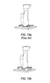
- FIGS. 19 a, b are pictures of an elbow penetration simulation test.
- FIG. 20 is a graph of force displacement curves for 9 different embodiments.
- FIG. 21 is a graph of stress displacement curves for the disclosed structure.
- FIG. 22 is a schematic diagram of Harvard hip impact model and supporting equations.
- FIG. 23 is a graph of force vs. time for an example solution of a hip impact on a hard surface.
- FIG. 24 is a schematic diagram of a new model for Hip Impact.
- FIG. 25 is a graph of peak impact force comparisons for 7 embodiments of the structure.
- FIG. 26 a,b,c are force vs. time curve graphs for hard surface as compared to 17 mm, 26 mm and 48 mm embodiments of the structure.
- FIG. 27 a - d are graphs illustrating an analysis of data.
- FIG. 28 is a graph illustrating fatigue reduction as a function of mat hardness.
- FIG. 29 is a graph of a disclosed embodiment as compared to two competing implementations.
- FIG. 30 is a graph of a disclosed embodiment as compared to two competing implementations.
- FIG. 31 is a sectional elevation of an embodiment of the disclosed mat.
- FIG. 32 is a sectional elevation of an alternate embodiment of the disclosed mat.
- FIGS. 33 a,b are sections taken along lines 33 - 33 of FIG. 32 .
- the resulting peak force for an impact on concrete is 24,300N, more than four times the peak force predicted by the Harvard model and well in excess of the force required to fracture the hip. The value is not unreasonable, compared with measured peak forces from real impacts with similar impact energy on compliant surfaces of similar thickness to the soft tissue.
- This approach essentially maximizes the shock attenuation capacity of the soft tissue within the limits of the available soft tissue thickness. The approach is conservative, tending to underestimate the peak force of an impact on a hard surface and hence underestimating the cushioning effect of compliant surfaces.
- FIG. 24 shows the new hip impact model with the addition of a non-linear spring representing the elasticity of the surface against which the impact occurs.
- the impact of the falling mass, m is moderated by the compliant material properties of the soft tissue and the surface, which act in series.
- Soft tissue behavior is characterized by the non-linear stiffness function previously described. Damping is ignored.
- the two degrees of freedom of motion of the system are expressed as x m , the displacement of the mass, and x s , the compression of the surface.
- the stiffness of the surface material is a function not only of its material properties, but also of the geometry of the contact.
- the surface will behave like a more or less stiff spring, depending on the contact area and the curvature of a body contacting it.
- the Harvard model does not incorporate contact geometry, and the geometry of contact between the hip and the surface is unknown.
- the contact was assumed to that of a rigid, penetrator with a 0.08 m radius, flat contact area.
- the surface model was constrained to compress by no more than 80% of it's original thickness, at which point it is assumed to have a high stiffness, approaching that of a very hard surface
- Table 2 shows the calculated peak force of a hip impact on each of the test surfaces, assuming an impact velocity of 4.25 m s ⁇ 1 and an effective mass of 39 kg. These results are also graphically illustrated in FIGS. 25 and 26 a - c .
- FIG. 1 is a cross-sectional view of one embodiment of elastomeric mat with domed cylinders with sloped or tapered walls and a top surface and elastomeric linkages or bridges.
- FIG. 2 is a cross-sectional view of an alternate embodiment of elastomeric mat with domed cylinders with sloped walls and top surface, but without elastomeric bridges.
- FIGS. 3 and 4 are bottom plan views of the mats of FIGS. 1 and 2 , respectively.
- FIG. 5 is a top plan view of a group or array of mats with a rigid ramp attached around three sides of the mat array.
- Elastomeric mat 4 has a top surface 1 with underlying subsurface hollow domed cylinders 2 . These elastomeric cylinders may or may not be tapered on the inside of the cylinder as can be seen at 2 in FIG. 2 (exaggerated). The material properties of elastomeric cylinders are described with a data plot and accompanying table in FIGS. 14 and 15 . Lower zone 6 of cylinder 2 is the zone that first flexes or deforms or collapses as load is gradually applied to top surface 1 of mat 4 .
- Elastomeric bridges or linkages 3 link cylinders 2 together in some embodiments.
- Such linkages provide added stability and rigidity to an upper zone of cylinder 2 and render the upper zone relatively incollapsible as load is applied, as compared with the relatively more flexible, compressible, and collapsible lower zone or foot 6 of cylinders 2 which do not have such linkages.
- Elastomeric mat 4 is preferably made of conventional rubber and other conventional elastomer molding technology. Mat sizes depend on the size of the mold used, which can vary from small rectangles of perhaps 1 inch square to large rectangles of 100 square feet or more. Mats 4 are abutted together as in FIG. 5 and then can be surrounded by a ramp 5 for ease of walking up on or walking off the mat surface. Sloped edges or integral ramps may also be molded in to the mat and made of the same material as the mat.
- FIG. 6 is a side cross-sectional view of the clip of FIG. 7 .
- FIG. 7 is a top plan view of a fenestrated or holed joining clip for use in connecting a ramp piece to a mat.
- FIG. 8 is a top plan view of an alternate fenestrated or holed joining clip for use in connecting neighboring mats in an array of mats. Grid spacing between rows of holes in the clip cause mats to be joined so as to provide a drainage space between mats for liquids to flow from the top surface down between the mats, or the grid spacing of the holes of the clip can fit the mats tightly next to each other.
- Clip 12 with holes 7 as seen in FIG. 8 can be used to adjoin neighboring pads as shown in FIG. 13 forming larger surface areas.
- Clip 11 with holes 7 as seen in FIG. 7 can be used to adjoin ramps to mats or pads 4 as shown in FIG. 11 .
- FIG. 9 is a bottom perspective view of a mat that has elastomeric bridges between flexing cylinders.
- FIG. 10 is a cross-sectional view of a rigid ramp 5 abutted to mat 4 .
- Ramp 5 is attached to the floor surface in preferred embodiments by screws 8 , but can also be attached by glue or other suitable means.
- the mat can be attached to the vertical ramp face by glue or clip (see FIG. 11 ).
- FIG. 11 is a cross-sectional view of a ramp abutted to a mat, with the clip of FIG. 7 joining the ramp and mat.
- regions of relatively firmer support 15 and adjacent regions of relatively softer support 16 These correspond respectively to the region 15 just about the supporting column, while region 16 is anything left over that is not above a supporting column.
- the firm zone 15 will be about 5 ⁇ 8 inch in diameter every 3 ⁇ 4 inch, and the rest will be region(s) 16 .
- FIG. 12 is a cross-sectional view of top surface spacer 14 advantageously used to keep mats spaced in an array a selected distance apart. This structure is advantageously used underneath carpet, artificial turf or other permeable surface coverings to allow drainage of liquids between the mats or pads. Clip 12 as seen in FIG. 13 or top surface spacer 14 as seen in FIG. 12 can be used to set the spacing between mats to allow liquid to pass down between the mats if needed.
- FIG. 13 is a cross-sectional view of clip 12 of FIG. 8 joining neighboring mats 4 and providing a selected spacing between them.
- Thick- Stiff- E 0.25 Test ness Area ness Modulus # Client's Sample ID mm cm kN m ⁇ 1 Mpa 2094 sample VALS 35.4 90.3 258 1.01 2095 sample 08608 (Rondy) 35.4 90.3 636 2.49 2096 sample DEC 7s (valley) 25.0 90.3 471 1.30 2097 sample DEC 102s (Rondy) 25.0 90.3 668 1.85 2098 sample DEC 11s (Valley) 17.5 90.3 1087 2.11 2099 sample DEC 16s (Rondy) 17.5 90.3 996 1.93 2100 sample DEC 13s (Intertex) 17.5 90.3 1100 2.13 2143 sample DEC 103s (Valley) 25.0 90.3 507 1.40
- FIG. 14 is a force vs. displacement curve showing material compression range for the 8 different samples from the above table.
- FIG. 15 is a stress vs. strain curve showing material response to stress for the 8 different samples from the above table.
- FIGS. 16 a - b are schematics of a conventional closed cell foam cushion at rest and under load, respectively.
- the foam cushion shows an unstable condition as the surface deforms under the load, leading potentially to dangerous binding of a foot due to the surface deformation. Impact energy is absorbed by crushing the foam cells from top to bottom, and the material gets just gets ‘harder’ under load.
- FIGS. 17 a, b are pictures of disclosed embodiments of elastomeric structure, at rest and under load, respectively. Note that as the structure takes impact or load, surface deformation is minimal, there is no tendency to bind a foot, impact energy is absorbed by ‘controlled’ buckling or collapse of the structure (cylinder is illustrated) at a lower zone of the structure, not at the top of the structure. The material thus gets ‘softer’ under load, as the collapsible structure continues to deform.
- FIGS. 18 a, b are pictures of a foot lock simulation test, showing conventional foam backed artificial turf and one of the disclosed elastomeric structures covered with artificial turf, respectively. In each case the foot is planted with 500 pounds of force. The degree of top surface deformation in the foam ( 18 a ) is evident as compared with the minimal deformation in the disclosed structure surface.
- FIGS. 19 a, b are pictures of an elbow penetration simulation test, showing conventional foam backed artificial turf and one of the disclosed elastomeric structures covered with artificial turf, respectively.
- the elbow is planted with 500 pounds of force.
- the degree of bottoming out in the foam ( 19 a ) is evident as compared with the appreciable penetration with no bottoming out in the disclosed structure surface.
- Table 4 contains results of constant velocity force-displacement test to 50% strain at 1 mm s ⁇ 1 on a Tinius Olsen UTM to generate force displacement curves, presented for 9 different embodiments of disclosed structure, including measured elastic modulus and stiffness properties.
- FIG. 20 is a graph of force (stress) displacement curves for the 9 different embodiments of disclosed structure shown in the above table. Energy absorption capability is unique as exemplified by shape of the force-displacement curve. The area under each curve is the amount of energy absorbed by that sample.
- Table 5 contains drop test data presented for 3 different embodiments of disclosed structure, including Gmax and HIC data for the structures in a 1.75 inch thick Smart Cells® Mat embodiment at 55° F. Data measured according to ASTM F-1292 and F-355 tests.
- HIC 1000 Standard Mat 1 5 120 2 5 126 664 3 5 125 665 Average 5 125.5 664.5 1 6 144 874 2 6 141 832 3 6 141 859 Average 6 141 845.5 1 7 159 1021 2 7 172 1200 3 7 168 1164 Average 7 170 1182 6.4 Mat covered 1 5 119 650 with Turf 2 5 119 658 3 5 119 656 Average 5 119 657 1 6 134 825 2 6 136 820 3 6 138 852 Average 6 137 836 1 7 139 939 2 7 148 1031 3 7 153 1091 Average 7 150.5 1061 6.7 Mat with 1 5 122 640 drainage holes 2 5 118 614 3 5 118 613 Average 5 118 613.5 1 6 142 865 2 6 144 881 3 6 146 898 Average 6 145 889.5 1 7 159 1000 2 7 16
- FIG. 21 is a graph of stress displacement curves for an embodiment of the disclosed structure as compared to two competitive implementations. For a given displacement the disclosed structure absorbs more energy than competitive products (area under the curve is the greatest for the disclosed sample).
- FIG. 22 is a schematic diagram of Harvard hip impact model and supporting equations.
- FIG. 23 is a graph of force vs. time for an example solution of a hip impact on a hard surface using the Harvard model.
- FIG. 24 is a schematic diagram of a new model for Hip Impact using accurate soft tissue component and structure component.
- FIG. 25 is a graph of peak impact force comparisons for 7 embodiments of the structure as if a hip were impacting the structure.
- FIG. 26 a,b,c are force vs. time curve graphs for hard surface as compared to 17 mm, 26 mm and 48 mm embodiments of the structure.
- FIG. 27 a - d are graphs illustrating an analysis of data from the literature, showing the effects of different surface materials on perception of fatigue.
- FIG. 28 is a graph illustrating fatigue reduction as a function of mat hardness.
- the middle vertical bar indicates optimal performance by one of the embodiments disclosed herein, while the vertical bars to the left and right indicate performance by competitor models that are either too hard or too soft.
- FIG. 29 is a graph of a disclosed embodiment as compared to two competing implementations. Mat stiffness, as a function of pressure applied to the mat, initially increase, over a very small initial pressure range, but then for the disclosed embodiment dramatically falls off as pressure is increased, illustrating the unique property of disclosed embodiments that they actually get softer as pressure is applied.
- FIG. 30 is a graph of a disclosed embodiment as compared to two competing implementations, plotting mat compliance vs. pressure applied to the mat.
- FIG. 31 is a sectional elevation of an embodiment of disclosed mat 100 .
- Mat 100 has upper layer 110 , also sometimes referred to herein as surface layer.
- Upper layer 110 is supported by column 120 .
- Column 120 may be any ready and appropriate shape, but regular geometric shapes are preferred, and a cylindrical or frusto-conical shape is advantageous in ease of production, and will be discussed here as the model for all such columns. (Except for particular discussion of the draft and other taper angles of column 120 in the frusto-conical column model, for ease of reference, the column will at times typically be referred to as a cylinder.)
- Column 120 has a column base 127 , also referred to herein sometimes as the column foot, or just the foot. It is the part of the column wall that touches the flooring or sub-base structure that underlies the matting system.
- Column base 127 has a width d.
- the enclosed void is optionally dome shaped 128 at the top of the void.
- the wall of column 120 has two zones, upper zone 103 and lower zone 105 ; upper zone 103 is relatively resistant to collapse, unlike lower zone 105 which is designed not only to take all of the working load compression, but also the initial over load collapse or deformation, and is relatively much more compressible that upper zone 103 .
- Lower zone typical compression is attended by a moderate deformation shown at paired dotted lines 109 as a slight bulge, both outward and inward, as the compressional forces (arrows 101 ) work to compress the elastomeric material vertically in height and cause the material to bulge away from the wall's resting boundaries.
- lower zone 105 actually buckles or collapses in severe deformation in the manner and in the directions indicated by paired dashed lines 107 and arrow 104 .
- the material ceases essentially to compress or bulge further, and instead collapses outwardly (relative to the center of the column) in the characteristic buckled collapse shown schematically.
- Upper zone 103 acts mostly passively throughout both the early and then severe compression and deformation of the lower zone. Depending on forces involved and the dimensions and properties of the rubber and column, upper zone 103 will exhibit only slight bulging, schematically represented by paired dotted lines 102 . This difference is designed, and while other, as yet not fully appreciated, factors may be at work, it is believed that the pronounced differential in compression effect and eventual buckling collapse (lower zone 105 only) is due to a significant difference in the geometry of zone 103 compared to zone 105 . Zone 105 starts out at the bottom as relatively narrow in cross-section, increasing in thickness until it reaches about 20-25% again as much thickness as it had at the bottom (120-125% of column base width d).
- FIG. 31 shows gradual tapering of lower zone 105 up into upper zone 103 , crossing only a virtual boundary 106 between the zones
- other embodiments will make the boundary explicit by employing increased thickening upwards in other than gradual or tapered fashion.
- upper zone 103 could have a sudden thickness change, perhaps even by way of a thickened step at or around boundary 106 , so that the increased thickness is suddenly achieved, rather than gradually.
- Lower step 105 may likewise be ‘stepped’ but will remain the defined lower zone, it is believed, only while column wall thickness does not exceed about 125% of the base width d.
- column 120 is a hollow truncated cone.
- the void inside the cone starts at bottom opening 108 and tapers, preferably, up to the point of curvature of the optional dome top 128 of the void.
- the outside wall of column 120 also preferably tapers upwardly until it joins with the bottom of upper layer 110 .
- the outer wall surface thus has a draft angle • 125
- the inner wall preferably has draft angle • 123 .
- angle • 125 will be greater than angle • 123 , and angle • will have a value in the range of 1-4.7 degrees, while angle • will have a value in the range of >0-4.5 degrees.
- the preferred draft angles will be about 4.7 degrees for angle • and about 4.1 degrees for angle •.
- boundary 106 will be located about 1.5 to 1.85 inches from the column base 127 .
- the preferred draft angles will be about 2.4 degrees for angle • and about 0.6 degrees for angle •.
- Density of columns 120 under upper layer 110 is based on a preferred about 0.6-0.0625 upper conical diameter and columns placed on about 3 ⁇ 4 inch centers, so that there will typically be about 256 columns per square foot of matting.
- FIG. 32 is a sectional elevation of an alternate embodiment of disclosed mat 100 .
- Upper zone z 1 and lower zone z 2 are defined in the same manner as discussed above for FIG. 31 .
- Upper layer 110 has a thickness t and column 120 has a height h; mat 100 has overall thickness T.
- preferred embodiments will have a ration of h:t>3.5, where preferred thicknesses of upper layer 110 in various embodiments are as follows: 0.18 for 1 ⁇ 2 inch pad; 0.20-0.25 (preferably 0.22) for the 1 inch pad; and 0.25-0.35 (preferably 0.33) for the 2 inch pad.
- Column 120 has width C at the top of the column, just under the upper layer 110 .
- the void has an uppermost width w, just before any dome 128 .
- column 120 has a stiffening rib 140 and/or a linkage or bridge 130 (connecting to other columns and to the underside of upper layer 110 ).
- the effect of the rib 140 or link 130 is to make the upper zone or z 1 that much stiffer and so enhance the effects discussed for FIG. 31 for upper zone 103 or z 2 here.
- At least one effect is that, to the extent a rib 140 or link 130 is joined to column 120 , the column width at that point is significantly and effectively greater than below the rib or link, or elsewhere around the column.
- Rib or link optionally have a taper as shown in FIG. 33 a, b which is a section taken along lines 33 - 33 of FIG. 32 ; the taper may optionally end in a rounded rib bottom or a flat bottom.
- Column base 127 has a width d
- the graphs of FIGS. 27 a - d present an analysis of Redfern's data, showing the effects of different surface materials on perception of fatigue.
- the “fatigue index” is the average of “tiredness” and “Leg Tiredness” ratings reported by Redfern.
- a quadratic curve fitted to the data using a least squares method shows a “minimum”, i.e. a value of the material property that would appear to minimize the perception of fatigue.
- Table 6 below lists the values of antifatigue mat properties that are thus predicted to produce the most favorable perception outcomes.
- Antifatigue mats appear to work by reducing pressure and encouraging the body to make small postural adjustments while standing.
- the small movements share the work of balancing among different parts of the leg muscles, so individual muscle fibers do less work and fatigue less rapidly.
- the postural adjustments also assist the body's “venous pump”. More blood circulates back to the heart instead of pooling in the legs and feet, causing swelling.
- the mat does not attenuate impact or reduce pressure on the foot as well, and does not allow the small postural adjustments that appear to reduce fatigue and improve circulation in the foot and leg, and may also focus loads on a few small muscle regions, accelerating fatigue.
- Disclosed mats are tuned to the ideal level of compliance that research shows maximizes antifatigue performance. Optimized performance ensures stability and support while reducing pressure on the feet, reducing leg shock and maximizing fatigue reduction.
- the disclosed structures create a regular pattern of very slightly firmer zones about 0.6 inches across and approximately 3 ⁇ 4 inch O.C. surrounded by very slightly softer zones.
- One early study of compliant flooring found that such small variations in the properties of a surface mat encourage small movements of the ankle and encourage blood flow, reducing fatigue and discomfort.
- Conventional compliant flooring materials compact and get hard when they are compressed. A foam mat that feels soft to the touch gets harder when you walk on it; harder even than some rubber mats.
- the unique structures disclosed herein are actually firm to the touch, but then get softer as applied pressure is increased. See FIGS. 29 and 30 .
- Preferred mats are made of an SBR/EPDM/natural rubber elastomeric material with the following properties: Shore A Durometer of 40 to 70 (more particularly 40-50 and most preferably about 44) measured on the surface of the mat; material compression measurements made using a 90 cm 2 sample and a 1 mm s ⁇ 2 compression rate as follows: stiffness of from about 100 kN per meter to about 2000 kN per meter; and modulus of from about 0.5 MPa to about 4 MPa, and more particularly at about 0.69 Mpa. Compressive modulus is believed to be optimized by controlling the product of the 300% elongation modulus figure and the Shore A durometer value.
- Antifatigue properties are believed to be optimized in the range of 200-400 psi for 300% elongation modulus value.
- Preferred elastomeric mats are made in thicknesses between 1 ⁇ 2 inch to 3 inches, and have a top, upper or surface layer across the elastomeric substructure array.
- This surface layer may advantageously be either a smooth or a rough surface and be either perforated or non-perforated.
- the preferred surface layer has a thickness of from about 0.16 to 0.30 inches and more preferably 0.18, 0.20-0.25 and 0.25-0.28 inches respectively for mats nominally sized at 1 ⁇ 2 inch, 1 inch and 2 inches. Other surface layer thicknesses may advantageously be employed in unusual situations.
- Mats can be joined and then covered with conventional industrial floor coatings, or with artificial turf, carpet, vinyl, rolled rubber or poured urethane.
- Mats can be of any conveniently manufactured size and, by abutting and joining multiple manufactured sizes, can cover an infinitely large surface area.
- Mats are preferably prevented from moving by providing a ramp or other type of dam or wall around the mats, or by adjoining neighboring mats with a joining clip or clips as described herein, or by gluing or taping the mats to the floor surface, or to each other.
- a preferred elastomeric substructure is a cylinder surrounding a void that tapers upwardly from a void opening of about 0.36 inches to about 0.31 inches and then is preferably domed above the taper.
- the preferred cylinder wall thickness is about 0.10 inches and the cylinder is preferably about 0.56 inches wide at its foot or base (the end of the cylinder that touches the floor or base surface), and tapers upwardly to a diameter of about 0.6 inches.
- Preferred substructures can be on a uniform grid or in a honey-combed configuration.
- Preferred substructures can be of circular, elliptical, or multi-sided shape from three sided to 20 sided or more.
- Preferred substructures can have a shared wall configuration without elastomeric bridge linkage between the cylinders on the one hand, or can alternatively be joined to one another by elastomeric linkages varying in length of from several hundredths of an inch long to about 2 inches, but preferably about 1 ⁇ 8 inch, and have width of from several hundredths of an inch to about 1 ⁇ 2 an inch, but preferably about 1 ⁇ 8 inch.
- a properly designed antifatigue mat increases comfort and reduces tiredness and swelling of the feet and legs.
- Disclosed mats are tuned to the ideal level of compliance that research shows maximizes antifatigue performance. Optimized performance ensures stability and support while reducing pressure on the feet, reducing leg shock and maximizing fatigue reduction.
- Conventional compliant flooring materials compact and get hard when they are compressed. The unique structures disclosed herein are actually firm to the touch, but then get softer as applied pressure is increased. Working people who must stand at their jobs are more productive when less fatigued and have less back, foot and leg pain. This generally lead to fewer accidents.
Landscapes
- Engineering & Computer Science (AREA)
- Architecture (AREA)
- Civil Engineering (AREA)
- Structural Engineering (AREA)
- Health & Medical Sciences (AREA)
- General Health & Medical Sciences (AREA)
- Hospice & Palliative Care (AREA)
- Road Paving Structures (AREA)
- Floor Finish (AREA)
Abstract
Description
F=m(d 2 x m /dt 2)=c t(dx m /dt)=k t x m (1)
k t=90,440(1−e −F/114) (2)
c t=756(1−e −F/108) (3)
Effective Mass:
Robinovitch (1991) reports the average effective mass (m) involved in hip impact to be 39 kg for males in the muscle-relaxed state.
m=39.0 (4)
Initial Conditions:
dx m /dt (t=0)=3.19 ms−1 (5)
Also at time t=0:
xm=0
xs=0
d2xm/dt2=g=9.81 ms−2
Example Solution
dF/dx s =nk s x s n-1 (6)
dF/d(x m −x s)=2k t x t (7)
dx m /dF=dx t /dF+dx s /dF (8)
Surface Properties:
F=Qx n s (9)
| TABLE 1 |
| Surface Stiffness Constants |
| Linear | Non-Linear | ||
| Thickness | Stiffness | Stiffness Constants |
| Sample ID | mm | kN m−1 | | n |
| VALS |
| 48 | 332 | 3.37 × 10⁶ | 1.68 | |
| 0608 (Rondy) | 48 | 450 | 3.18 × 10⁵ | 0.91 |
| DEC16s (Rondy) | 17 | 978 | 2.98 × 10⁸ | 2.22 |
| DEC13s (Intertex) | 17 | 1054 | 2.29 × 10¹⁰ | 3.21 |
| DEC103s | 26 | 611 | 1.49 × 10⁹ | 2.93 |
| DEC102s (Rondy) | 26 | 705 | 4.40 × 10⁷ | 2.00 |
| DEC7s (Valley) | 26 | 611 | 1.74 × 10⁹ | 2.96 |
| Concrete Floor | ● | 1 × 10¹⁰ | 1 | |
Results
| TABLE 2 | |||||
| Peak | Peak | ||||
| Force | Shock | ||||
| Sample ID | kN | g | % | ||
| VALS | 11.7 | 31 | 52% | ||
| 8608 | 10.1 | 26 | 58 | ||
| DEC | |||||
| 16s | 18.5 | 48 | 24 | ||
| DEC | |||||
| 13 | 19.7 | 51 | 19 | ||
| DEC | |||||
| 103s | 17.2 | 45 | 29 | ||
| DEC | |||||
| 102s | 16.0 | 42 | 34 | ||
| DEC | |||||
| 7 | 17.3 | 45 | 29% | ||
| “Hard” Floor | 24.3 | 63 | 0% | ||
| TABLE 3 | |||||
| Thick- | Stiff- | E = 0.25 | |||
| Test | ness | Area | ness | Modulus | |
| # | Client's Sample ID | mm | cm | kN m−1 | |
| 2094 | sample VALS | 35.4 | 90.3 | 258 | 1.01 |
| 2095 | sample 08608 (Rondy) | 35.4 | 90.3 | 636 | 2.49 |
| 2096 | sample DEC 7s (valley) | 25.0 | 90.3 | 471 | 1.30 |
| 2097 | |
25.0 | 90.3 | 668 | 1.85 |
| 2098 | sample DEC 11s (Valley) | 17.5 | 90.3 | 1087 | 2.11 |
| 2099 | |
17.5 | 90.3 | 996 | 1.93 |
| 2100 | sample DEC 13s (Intertex) | 17.5 | 90.3 | 1100 | 2.13 |
| 2143 | |
25.0 | 90.3 | 507 | 1.40 |
| TABLE 4 |
| Force-Displacement Properties of Disclosed Embodiments |
| Thickness | Elastic | ‘Stiffness’ | ||
| Test # | Sample label | mm | Modulus MPa | Kg cm−2mm−1 |
| 2069 | |
26.1 | 1.19 | 0.47 |
| 2070 | |
25.9 | 1.05 | 0.41 |
| 2071 | |
25.1 | 0.96 | 0.39 |
| 2072 | VAL | 48.0 | 1.30 | 0.28 |
| 2073 | RON | 47.5 | 1.60 | 0.34 |
| 2074 | |
47.8 | 1.11 | 0.24 |
| 2075 | |
48.0 | 1.11 | 0.24 |
| 2076 | |
46.4 | 0.92 | 0.20 |
| 2077 | Old Mold | 49.3 | 1.11 | 0.23 |
| TABLE 5 | |||||
| Critical | |||||
| Height | |||||
| Site: 3, 4, 6 | Drop height | (feet) at | |||
| (per F 1936) | Drop | (feet) | G max | HIC | HIC = 1000 |
| |
1 | 5 | 120 | ||
| 2 | 5 | 126 | 664 | ||
| 3 | 5 | 125 | 665 | ||
| Average | 5 | 125.5 | 664.5 | ||
| 1 | 6 | 144 | 874 | ||
| 2 | 6 | 141 | 832 | ||
| 3 | 6 | 141 | 859 | ||
| Average | 6 | 141 | 845.5 | ||
| 1 | 7 | 159 | 1021 | ||
| 2 | 7 | 172 | 1200 | ||
| 3 | 7 | 168 | 1164 | ||
| |
7 | 170 | 1182 | 6.4 | |
| Mat covered | 1 | 5 | 119 | 650 | |
| with |
2 | 5 | 119 | 658 | |
| 3 | 5 | 119 | 656 | ||
| Average | 5 | 119 | 657 | ||
| 1 | 6 | 134 | 825 | ||
| 2 | 6 | 136 | 820 | ||
| 3 | 6 | 138 | 852 | ||
| Average | 6 | 137 | 836 | ||
| 1 | 7 | 139 | 939 | ||
| 2 | 7 | 148 | 1031 | ||
| 3 | 7 | 153 | 1091 | ||
| |
7 | 150.5 | 1061 | 6.7 | |
| Mat with | 1 | 5 | 122 | 640 | |
| |
2 | 5 | 118 | 614 | |
| 3 | 5 | 118 | 613 | ||
| Average | 5 | 118 | 613.5 | ||
| 1 | 6 | 142 | 865 | ||
| 2 | 6 | 144 | 881 | ||
| 3 | 6 | 146 | 898 | ||
| Average | 6 | 145 | 889.5 | ||
| 1 | 7 | 159 | 1000 | ||
| 2 | 7 | 163 | 1101 | ||
| 3 | 7 | 161 | 1121 | ||
| |
7 | 162 | 1111 | 6.5 | |
| TABLE 6 | |||
| Property | Value | ||
| Elastic Modulus | ~0.7 | MPa | ||
| Bottom Out Depth | >5 | mm | ||
| Densification Strain | >0.6 | |||
| Thickness | >10 | mm | ||
From these data it may be inferred that
1. The appropriate “hardness” of an antifatigue mat is that produced by a material with an elastic modulus in the range 0.5-0.9 MPa. Redfern's data suggests an optimum value of 0.69 MPa.
2. Given an appropriate hardness, the antifatigue mat must allow enough compression to accommodate normal loading conditions without bottoming out. The optimal modulus range implies mat compression of up to 50% during normal standing and stepping, so the densification strain (bottoming out point as a percentage of thickness) must exceed 50%.
3. Redfern's data suggest that mats with a bottoming out depth greater than 5 mm and a thickness greater than 10 mm produce the best results, unless they are too soft.
Claims (8)
Priority Applications (1)
| Application Number | Priority Date | Filing Date | Title |
|---|---|---|---|
| US12/543,282 US8241726B2 (en) | 2002-04-02 | 2009-08-18 | Impact absorbing safety matting system with elastomeric sub-surface structure |
Applications Claiming Priority (4)
| Application Number | Priority Date | Filing Date | Title |
|---|---|---|---|
| US36966502P | 2002-04-02 | 2002-04-02 | |
| US10/406,473 US7575795B2 (en) | 2002-04-02 | 2003-04-02 | Impact absorbing safety matting system with elastomeric sub-surface structure |
| US11/482,190 US7575796B2 (en) | 2002-04-02 | 2006-07-05 | Impact absorbing safety matting system with elastomeric sub-surface structure |
| US12/543,282 US8241726B2 (en) | 2002-04-02 | 2009-08-18 | Impact absorbing safety matting system with elastomeric sub-surface structure |
Related Parent Applications (1)
| Application Number | Title | Priority Date | Filing Date |
|---|---|---|---|
| US11/482,190 Division US7575796B2 (en) | 2002-04-02 | 2006-07-05 | Impact absorbing safety matting system with elastomeric sub-surface structure |
Publications (2)
| Publication Number | Publication Date |
|---|---|
| US20100098914A1 US20100098914A1 (en) | 2010-04-22 |
| US8241726B2 true US8241726B2 (en) | 2012-08-14 |
Family
ID=28457314
Family Applications (3)
| Application Number | Title | Priority Date | Filing Date |
|---|---|---|---|
| US10/406,473 Expired - Lifetime US7575795B2 (en) | 2002-04-02 | 2003-04-02 | Impact absorbing safety matting system with elastomeric sub-surface structure |
| US11/482,190 Expired - Lifetime US7575796B2 (en) | 2002-04-02 | 2006-07-05 | Impact absorbing safety matting system with elastomeric sub-surface structure |
| US12/543,282 Expired - Fee Related US8241726B2 (en) | 2002-04-02 | 2009-08-18 | Impact absorbing safety matting system with elastomeric sub-surface structure |
Family Applications Before (2)
| Application Number | Title | Priority Date | Filing Date |
|---|---|---|---|
| US10/406,473 Expired - Lifetime US7575795B2 (en) | 2002-04-02 | 2003-04-02 | Impact absorbing safety matting system with elastomeric sub-surface structure |
| US11/482,190 Expired - Lifetime US7575796B2 (en) | 2002-04-02 | 2006-07-05 | Impact absorbing safety matting system with elastomeric sub-surface structure |
Country Status (1)
| Country | Link |
|---|---|
| US (3) | US7575795B2 (en) |
Cited By (7)
| Publication number | Priority date | Publication date | Assignee | Title |
|---|---|---|---|---|
| US20130000228A1 (en) * | 2006-02-09 | 2013-01-03 | University Of Notre Dame Du Lac | Flooring apparatus for reducing impact energy during a fall |
| USD746955S1 (en) | 2014-11-03 | 2016-01-05 | Micah Corder | Drain cover |
| US9573086B2 (en) | 2014-11-03 | 2017-02-21 | Micah Corder | Drain cover |
| US9879432B2 (en) | 2015-08-19 | 2018-01-30 | Sportsfield Intellectual, Llc | Outdoor wall padding apparatus and methods for forming and using the same |
| US10045647B2 (en) | 2015-04-27 | 2018-08-14 | Jumpsport, Inc. | Standing surface to encourage movement |
| USD849856S1 (en) | 2017-06-28 | 2019-05-28 | Jumpsport, Inc. | Standing platform |
| US20200386509A1 (en) * | 2016-07-08 | 2020-12-10 | Bryce L. Betteridge | Impact Absorbing Padding System with Elastomeric Sub-surface Structure |
Families Citing this family (35)
| Publication number | Priority date | Publication date | Assignee | Title |
|---|---|---|---|---|
| US8099915B2 (en) | 2005-06-02 | 2012-01-24 | Snapsports Company | Modular floor tile with resilient support members |
| US7958681B2 (en) * | 2005-06-02 | 2011-06-14 | Moller Jr Jorgen J | Modular floor tile with nonslip insert system |
| US7488525B2 (en) * | 2005-10-14 | 2009-02-10 | Sof' Solutions, Inc. | Impact-attenuating, firm, stable, and slip-resistant surface system |
| AU2007213470B2 (en) * | 2006-02-09 | 2012-12-13 | University Of Notre Dame Du Lac | Flooring apparatus for reducing impact energy during a fall |
| US20080106014A1 (en) * | 2006-11-07 | 2008-05-08 | Gigl Joseph J | Pad for reducing or dampening noise or vibration |
| US20100041488A1 (en) * | 2008-08-14 | 2010-02-18 | Notts Sport Limited | Playing Surface and Method of Manufacturing a Playing Surface |
| EP2154291B8 (en) * | 2008-08-15 | 2013-12-18 | Notts Sport Group Limited | Playing surface, method of manufacturing a playing surface and method of laying a playing surface |
| AU2009316330A1 (en) * | 2008-11-24 | 2010-05-27 | Applied Ft Composite Solutions Inc. | Resilient pad composite and process for making same |
| WO2010092519A2 (en) * | 2009-02-13 | 2010-08-19 | Koninklijke Philips Electronics N.V. | Floor construction with variable grade of resilience |
| US20100237082A1 (en) * | 2009-03-20 | 2010-09-23 | Products Of Tomorrow, Inc. | Gel cushion mat |
| US8539728B2 (en) * | 2009-09-26 | 2013-09-24 | Sorbashock Llc | Flooring apparatus and systems for improved reduction of impact forces during a fall |
| US9085909B2 (en) * | 2010-01-18 | 2015-07-21 | Ray D. Kanter | Protective flooring system |
| KR20130000387A (en) * | 2010-02-11 | 2013-01-02 | 브록 인터내셔널 | Load supporting panel having impact absorbing structure |
| USD666044S1 (en) | 2010-05-27 | 2012-08-28 | Magnet Works, Ltd. | Frame for a modular anti-fatigue floor mat assembly |
| TW201233556A (en) | 2010-11-24 | 2012-08-16 | Applied Ft Composite Solutions Inc | Composite cushioning material and jigless method for making the same |
| EP2867017B1 (en) | 2012-07-02 | 2017-09-06 | Tarkett G.D.L. S.a. | Shock absorption flooring |
| WO2014007605A1 (en) | 2012-07-05 | 2014-01-09 | Permavoid Limited | Plant surface structure and method for forming the same |
| US20140053783A1 (en) * | 2012-08-24 | 2014-02-27 | Pet Fusion, Llc | Litter mat |
| CA2883884A1 (en) | 2012-09-07 | 2014-03-13 | Permavoid Limited | Cattle floor |
| CN102908033B (en) * | 2012-11-02 | 2015-08-12 | 浙江三门维艾尔工业有限公司 | A kind of Slippery proof foot pad |
| AU2015228894B2 (en) | 2014-03-12 | 2019-09-26 | Permavoid Limited | Sports field structure and method for forming the same |
| US10208434B2 (en) * | 2014-03-12 | 2019-02-19 | Permavoid Limited | Sports field structure and method for forming the same |
| JP6161648B2 (en) * | 2014-05-26 | 2017-07-12 | 豊田鉄工株式会社 | Stacked composite interior parts |
| US11871861B2 (en) * | 2015-03-09 | 2024-01-16 | Purple Innovation, Llc | Cushions comprising a non-slip elastomeric cushioning element |
| EP3433429B1 (en) * | 2016-03-24 | 2021-01-27 | Wholesale Turf Supply LLC | Fastening system |
| US10851863B2 (en) * | 2016-06-09 | 2020-12-01 | Bryce L. Betteridge | Impact absorbing matting and padding system with elastomeric sub-surface structure |
| MX2018006994A (en) * | 2016-10-31 | 2018-11-09 | Zhang Yue | Metal plate having hollow tubes sandwiched therein and its use. |
| US10178922B1 (en) | 2017-07-13 | 2019-01-15 | Ebco Inc. | Floor mat |
| GB2567461B (en) * | 2017-10-12 | 2023-05-03 | Staffordshire Univ | Deformable support structure |
| CN108937497A (en) * | 2018-10-17 | 2018-12-07 | 东方伟尚(北京)材料技术有限公司 | A kind of non-slip mat |
| US11585102B2 (en) * | 2018-11-07 | 2023-02-21 | Viconic Sporting Llc | Load distribution and absorption underpayment system |
| US10982451B2 (en) * | 2018-11-07 | 2021-04-20 | Viconic Sporting Llc | Progressive stage load distribution and absorption underlayment system |
| US20220064963A1 (en) * | 2020-08-26 | 2022-03-03 | Wearwell, Llc | Integrated mat assembly and method of use |
| JP7600620B2 (en) * | 2020-10-28 | 2024-12-17 | Toppanホールディングス株式会社 | Shock absorbing flooring |
| US12460427B2 (en) | 2022-06-30 | 2025-11-04 | Viconic Sporting Llc | Dual-purpose progressive stage load-distributing and absorbing system |
Citations (5)
| Publication number | Priority date | Publication date | Assignee | Title |
|---|---|---|---|---|
| US3438312A (en) * | 1965-10-22 | 1969-04-15 | Jean P M Becker | Ground covering capable for use in playing tennis in the open air or under cover |
| US4948116A (en) * | 1982-04-02 | 1990-08-14 | Vaux Thomas M | Impact-absorbing safety matting system for a children's play mat |
| US5234738A (en) * | 1991-08-07 | 1993-08-10 | Carlisle Tire & Rubber Company | Resilient tile for recreation surfaces |
| US5403637A (en) * | 1993-09-28 | 1995-04-04 | National Rubber Technology Inc. | Resilient surfacing system |
| US5618607A (en) * | 1993-10-21 | 1997-04-08 | Sumitomo Chemical Company, Limited | Plastic-made reinforced structure |
Family Cites Families (29)
| Publication number | Priority date | Publication date | Assignee | Title |
|---|---|---|---|---|
| US2653525A (en) * | 1950-01-16 | 1953-09-29 | Mcguire John Sargeant | Landing mat |
| US3305227A (en) * | 1964-11-13 | 1967-02-21 | Eagle Picher Co | High deflection spring or bumper |
| US3808628A (en) * | 1972-06-15 | 1974-05-07 | Specialties Const | Floor mat |
| FR2238091B1 (en) * | 1973-07-18 | 1976-07-23 | Kleber Colombes | |
| US4277055A (en) * | 1978-09-21 | 1981-07-07 | Sumitomo Rubber Industries, Ltd. | Cushioning fender |
| JPS5631913A (en) | 1979-08-21 | 1981-03-31 | Yokohama Rubber Co Ltd:The | Fender |
| JPS56131848A (en) | 1980-03-21 | 1981-10-15 | Koryo Miura | Energy absorbing element |
| JPS56131849A (en) | 1980-03-21 | 1981-10-15 | Koryo Miura | Energy absorbing element |
| DK155616C (en) * | 1984-09-25 | 1989-09-04 | Eminent Plast | GRID OR MEASUREMENT ELEMENT FOR THE CREATION OF A FLOOR COVERING BY CONNECTION WITH SIMILAR ELEMENTS |
| US4604509A (en) * | 1985-02-01 | 1986-08-05 | Honeywell Inc. | Elastomeric push button return element for providing enhanced tactile feedback |
| GB8713995D0 (en) | 1987-06-16 | 1987-07-22 | Smp Playgrounds Ltd | Tiles |
| US4805886A (en) * | 1988-04-11 | 1989-02-21 | Chrysler Motors Corporation | Jounce bumper assembly for vehicle suspension strut |
| GB2218201B (en) | 1988-04-30 | 1991-06-19 | Wilkinson & Simpson Ltd | Method and product for determining cationic compounds |
| US4848058A (en) * | 1988-06-21 | 1989-07-18 | Carlisle Tire & Rubber Company | Recreation surface and tile interlocking scheme |
| US4921741A (en) * | 1988-06-21 | 1990-05-01 | Carlisle Tire & Rubber Company | Recreation surface and tile fastening scheme |
| US5433052A (en) * | 1989-02-08 | 1995-07-18 | Robbins, Inc. | Kerfed hardwood floor system |
| DK89291D0 (en) * | 1991-05-13 | 1991-05-13 | Frank Bentzon | FLOORING SYSTEM WITH LINKABLE TILE ELEMENTS, NAMELY PLASTIC TILES |
| US5572804A (en) * | 1991-09-26 | 1996-11-12 | Retama Technology Corp. | Shoe sole component and shoe sole component construction method |
| US5251742A (en) * | 1991-11-21 | 1993-10-12 | Cp Rubber, A Div. Of Starcan Corporation | Conveyor installation and shock absorbing elements for use therein |
| US5749111A (en) * | 1996-02-14 | 1998-05-12 | Teksource, Lc | Gelatinous cushions with buckling columns |
| US6044606A (en) * | 1997-08-15 | 2000-04-04 | Horner Flooring, Inc. | Floor system |
| US5961556A (en) * | 1996-12-31 | 1999-10-05 | Lord Corporation | Prosthetic suspension unit having elastomeric energy storage units |
| US5958538A (en) * | 1997-03-24 | 1999-09-28 | R & L Marketing Sales, Inc. | Floor mat system |
| US5992105A (en) * | 1997-06-24 | 1999-11-30 | R & J Marketing & Sales, Inc. | Spillage control safety floor matting |
| US6029962A (en) * | 1997-10-24 | 2000-02-29 | Retama Technology Corporation | Shock absorbing component and construction method |
| US6394432B1 (en) * | 1998-06-10 | 2002-05-28 | Lord Corporation | Vibration and/or shock absorbing devices and compensator elements utilized therein |
| KR100640030B1 (en) * | 1999-12-20 | 2006-10-31 | 스미도모 고무 고교 가부시기가이샤 | Fender |
| US6487796B1 (en) * | 2001-01-02 | 2002-12-03 | Nike, Inc. | Footwear with lateral stabilizing sole |
| US6457261B1 (en) * | 2001-01-22 | 2002-10-01 | Ll International Shoe Company, Inc. | Shock absorbing midsole for an athletic shoe |
-
2003
- 2003-04-02 US US10/406,473 patent/US7575795B2/en not_active Expired - Lifetime
-
2006
- 2006-07-05 US US11/482,190 patent/US7575796B2/en not_active Expired - Lifetime
-
2009
- 2009-08-18 US US12/543,282 patent/US8241726B2/en not_active Expired - Fee Related
Patent Citations (5)
| Publication number | Priority date | Publication date | Assignee | Title |
|---|---|---|---|---|
| US3438312A (en) * | 1965-10-22 | 1969-04-15 | Jean P M Becker | Ground covering capable for use in playing tennis in the open air or under cover |
| US4948116A (en) * | 1982-04-02 | 1990-08-14 | Vaux Thomas M | Impact-absorbing safety matting system for a children's play mat |
| US5234738A (en) * | 1991-08-07 | 1993-08-10 | Carlisle Tire & Rubber Company | Resilient tile for recreation surfaces |
| US5403637A (en) * | 1993-09-28 | 1995-04-04 | National Rubber Technology Inc. | Resilient surfacing system |
| US5618607A (en) * | 1993-10-21 | 1997-04-08 | Sumitomo Chemical Company, Limited | Plastic-made reinforced structure |
Cited By (9)
| Publication number | Priority date | Publication date | Assignee | Title |
|---|---|---|---|---|
| US20130000228A1 (en) * | 2006-02-09 | 2013-01-03 | University Of Notre Dame Du Lac | Flooring apparatus for reducing impact energy during a fall |
| US8919066B2 (en) * | 2006-02-09 | 2014-12-30 | University Of Notre Dame Du Lac | Flooring apparatus for reducing impact energy during a fall |
| USD746955S1 (en) | 2014-11-03 | 2016-01-05 | Micah Corder | Drain cover |
| US9573086B2 (en) | 2014-11-03 | 2017-02-21 | Micah Corder | Drain cover |
| US10045647B2 (en) | 2015-04-27 | 2018-08-14 | Jumpsport, Inc. | Standing surface to encourage movement |
| US11172775B2 (en) | 2015-04-27 | 2021-11-16 | Jumpsport, Inc. | Standing surface to encourage movement |
| US9879432B2 (en) | 2015-08-19 | 2018-01-30 | Sportsfield Intellectual, Llc | Outdoor wall padding apparatus and methods for forming and using the same |
| US20200386509A1 (en) * | 2016-07-08 | 2020-12-10 | Bryce L. Betteridge | Impact Absorbing Padding System with Elastomeric Sub-surface Structure |
| USD849856S1 (en) | 2017-06-28 | 2019-05-28 | Jumpsport, Inc. | Standing platform |
Also Published As
| Publication number | Publication date |
|---|---|
| US7575796B2 (en) | 2009-08-18 |
| US7575795B2 (en) | 2009-08-18 |
| US20100098914A1 (en) | 2010-04-22 |
| US20070092694A1 (en) | 2007-04-26 |
| US20030186025A1 (en) | 2003-10-02 |
Similar Documents
| Publication | Publication Date | Title |
|---|---|---|
| US8241726B2 (en) | Impact absorbing safety matting system with elastomeric sub-surface structure | |
| EP3469167B1 (en) | Impact absorbing safety matting and padding system with elastomeric sub-surface structure | |
| US20250212990A1 (en) | Random variable stimulus insoles and footwear to optimize human neuromuscular gait mechanics | |
| Robbins et al. | Balance and vertical impact in sports: role of shoe sole materials | |
| US7886388B2 (en) | Mattress adapted for supporting heavy weight persons | |
| Wright et al. | The influence of headform orientation and flooring systems on impact dynamics during simulated fall-related head impacts | |
| JPH0354738Y2 (en) | ||
| Robbins et al. | Improving balance | |
| Glinka et al. | Characterization of the protective capacity of flooring systems using force-deflection profiling | |
| Casalena et al. | The Penn State Safety Floor: Part II—Reduction of fall-related peak impact forces on the femur | |
| KR102127031B1 (en) | Insole | |
| AU2010299605B2 (en) | Multilayer insole to be fitted in footwear and the like | |
| CN100405947C (en) | Method for providing an insole for a shoe for increasing sensory stimulation and insole suitable for the method | |
| EP4349200A2 (en) | Shock-absorbing material | |
| US12366075B2 (en) | Impact absorbing flooring | |
| WO2003085223A1 (en) | Impact absorbing safety matting system with elastomeric sub-surface structure | |
| JP2023164936A (en) | flooring system | |
| US12460427B2 (en) | Dual-purpose progressive stage load-distributing and absorbing system | |
| Redfern et al. | The effects of floor types on standing tolerance in industry | |
| McFarland | Freestall design: Cow recommended refinements | |
| Mashhouri | Applying safe flooring in housing environments related to the independent elderly: evaluating suitability flooring technology to absorb impact in the event of a fall | |
| US7941875B1 (en) | Trabecular matrix like protectors and method | |
| Lavender et al. | Ergonomic principles applied to the prevention of injuries to the lower extremity | |
| US20240309658A1 (en) | Dual-purpose progressive stage load-distributing and absorbing system | |
| Bidar et al. | Finite element calculation of seat-interface pressures for various wheelchair cushion thicknesses |
Legal Events
| Date | Code | Title | Description |
|---|---|---|---|
| ZAAA | Notice of allowance and fees due |
Free format text: ORIGINAL CODE: NOA |
|
| ZAAB | Notice of allowance mailed |
Free format text: ORIGINAL CODE: MN/=. |
|
| STCF | Information on status: patent grant |
Free format text: PATENTED CASE |
|
| REMI | Maintenance fee reminder mailed | ||
| FPAY | Fee payment |
Year of fee payment: 4 |
|
| SULP | Surcharge for late payment | ||
| FEPP | Fee payment procedure |
Free format text: MAINTENANCE FEE REMINDER MAILED (ORIGINAL EVENT CODE: REM.); ENTITY STATUS OF PATENT OWNER: SMALL ENTITY |
|
| FEPP | Fee payment procedure |
Free format text: 7.5 YR SURCHARGE - LATE PMT W/IN 6 MO, SMALL ENTITY (ORIGINAL EVENT CODE: M2555); ENTITY STATUS OF PATENT OWNER: SMALL ENTITY |
|
| MAFP | Maintenance fee payment |
Free format text: PAYMENT OF MAINTENANCE FEE, 8TH YR, SMALL ENTITY (ORIGINAL EVENT CODE: M2552); ENTITY STATUS OF PATENT OWNER: SMALL ENTITY Year of fee payment: 8 |
|
| FEPP | Fee payment procedure |
Free format text: MAINTENANCE FEE REMINDER MAILED (ORIGINAL EVENT CODE: REM.); ENTITY STATUS OF PATENT OWNER: SMALL ENTITY |
|
| LAPS | Lapse for failure to pay maintenance fees |
Free format text: PATENT EXPIRED FOR FAILURE TO PAY MAINTENANCE FEES (ORIGINAL EVENT CODE: EXP.); ENTITY STATUS OF PATENT OWNER: SMALL ENTITY |
|
| STCH | Information on status: patent discontinuation |
Free format text: PATENT EXPIRED DUE TO NONPAYMENT OF MAINTENANCE FEES UNDER 37 CFR 1.362 |
|
| FP | Lapsed due to failure to pay maintenance fee |
Effective date: 20240814 |