US8224083B2 - Extraction of illumination light image in an image processing apparatus, and image processing method and storage medium therefor - Google Patents
Extraction of illumination light image in an image processing apparatus, and image processing method and storage medium therefor Download PDFInfo
- Publication number
- US8224083B2 US8224083B2 US12/579,916 US57991609A US8224083B2 US 8224083 B2 US8224083 B2 US 8224083B2 US 57991609 A US57991609 A US 57991609A US 8224083 B2 US8224083 B2 US 8224083B2
- Authority
- US
- United States
- Prior art keywords
- image
- read image
- reflection
- pixels
- read
- Prior art date
- Legal status (The legal status is an assumption and is not a legal conclusion. Google has not performed a legal analysis and makes no representation as to the accuracy of the status listed.)
- Expired - Fee Related, expires
Links
- 238000012545 processing Methods 0.000 title claims description 89
- 238000003672 processing method Methods 0.000 title claims description 5
- 238000005286 illumination Methods 0.000 title description 49
- 238000000605 extraction Methods 0.000 title 1
- 230000008859 change Effects 0.000 claims abstract description 20
- 238000012937 correction Methods 0.000 claims description 42
- 238000000034 method Methods 0.000 description 19
- 238000006243 chemical reaction Methods 0.000 description 12
- 238000013459 approach Methods 0.000 description 7
- 230000008901 benefit Effects 0.000 description 3
- 239000000470 constituent Substances 0.000 description 3
- 238000005516 engineering process Methods 0.000 description 3
- 230000001678 irradiating effect Effects 0.000 description 3
- 230000003595 spectral effect Effects 0.000 description 3
- 241000519995 Stachys sylvatica Species 0.000 description 2
- 230000001174 ascending effect Effects 0.000 description 2
- 230000015556 catabolic process Effects 0.000 description 2
- 238000006731 degradation reaction Methods 0.000 description 2
- 238000010586 diagram Methods 0.000 description 2
- 230000000694 effects Effects 0.000 description 2
- 238000001914 filtration Methods 0.000 description 2
- 230000007246 mechanism Effects 0.000 description 2
- 230000009467 reduction Effects 0.000 description 2
- 241000755266 Kathetostoma giganteum Species 0.000 description 1
- 230000002146 bilateral effect Effects 0.000 description 1
- 239000011248 coating agent Substances 0.000 description 1
- 238000000576 coating method Methods 0.000 description 1
- 230000000295 complement effect Effects 0.000 description 1
- 238000007667 floating Methods 0.000 description 1
- 230000013011 mating Effects 0.000 description 1
- 229910044991 metal oxide Inorganic materials 0.000 description 1
- 150000004706 metal oxides Chemical class 0.000 description 1
- 238000012986 modification Methods 0.000 description 1
- 230000004048 modification Effects 0.000 description 1
- 238000012805 post-processing Methods 0.000 description 1
- 238000007639 printing Methods 0.000 description 1
- 238000005070 sampling Methods 0.000 description 1
- 229920006395 saturated elastomer Polymers 0.000 description 1
- 239000004065 semiconductor Substances 0.000 description 1
- 238000002834 transmittance Methods 0.000 description 1
- 229910052724 xenon Inorganic materials 0.000 description 1
- FHNFHKCVQCLJFQ-UHFFFAOYSA-N xenon atom Chemical compound [Xe] FHNFHKCVQCLJFQ-UHFFFAOYSA-N 0.000 description 1
Images


Classifications
-
- H—ELECTRICITY
- H04—ELECTRIC COMMUNICATION TECHNIQUE
- H04N—PICTORIAL COMMUNICATION, e.g. TELEVISION
- H04N1/00—Scanning, transmission or reproduction of documents or the like, e.g. facsimile transmission; Details thereof
- H04N1/387—Composing, repositioning or otherwise geometrically modifying originals
-
- H—ELECTRICITY
- H04—ELECTRIC COMMUNICATION TECHNIQUE
- H04N—PICTORIAL COMMUNICATION, e.g. TELEVISION
- H04N1/00—Scanning, transmission or reproduction of documents or the like, e.g. facsimile transmission; Details thereof
- H04N1/40—Picture signal circuits
- H04N1/407—Control or modification of tonal gradation or of extreme levels, e.g. background level
- H04N1/4072—Control or modification of tonal gradation or of extreme levels, e.g. background level dependent on the contents of the original
Definitions
- the present invention relates to an image processing apparatus, an image processing method, and storage medium for processing an image obtained by reading a manuscript while irradiating it with light, and to a storage medium.
- a copier, a flat-head scanner and a facsimile etc. have been widely used as means for reading image information of a manuscript (document) electronically.
- an image reading apparatus for reading an open page of a thick pamphlet or a book etc. from above.
- Manuscripts read by these image reading apparatuses include one-sheet-of paper shaped manuscripts such as a copier paper and a post card, and thick book shaped manuscripts such as a book and a magazine.
- the manuscripts having the latter shape (hereinafter referred to as book manuscripts) have a significant feature in that an opened page to be a read surface is not flat.
- the image processing apparatus for processing the image obtained by reading a manuscript while irradiating it with light is constructed as in FIG. 1 .
- reference numeral 101 denotes a platen; 102 and 118 , light sources; 103 , a reflection mirror; 104 , a reading sensor; 105 , a platen cover; 106 , a controller; 107 , a bus; 108 , a setting UI; and 111 , a lens.
- Reference numeral 110 denotes a reading device including necessary components for reading a manuscript. An internal state of the reading device 110 when reading a manuscript set with its manuscript surface downward on the platen 101 will be described with reference to FIG. 3A .
- the light sources 102 and 118 emit light.
- the light sources 102 and 118 have spectral intensity in a wavelength region approximately within that of visible light.
- the manuscript is irradiated with the light from the light sources 102 and 118 , and the light reflected on the manuscript is reflected by a plurality of reflection mirrors 103 and collected by the lens 111 to enter the reading sensor 104 .
- the reading sensor 104 includes at least a photoelectric conversion element, accumulates electric charges having an amount according to the intensity of the incident light, and converts the electric charges into digital data using an A/D converter not shown in the figure, thereby converting the image information on the manuscript into digital image data.
- the digital data is processed in the controller 106 . Intensity of the light incident on the reading sensor 104 depends on the distribution of spectral reflectance contained in the information of the manuscript.
- the above-mentioned configuration of the image processing apparatus is a minimum combination required for constructing such a type of scanner that reads a manuscript surface while irradiating it with light from below the platen.
- exemplary configuration may include one having a different number of mirrors or one having a different reading sensor.
- the reading sensor may be CCD or CMOS.
- COD is abbreviation of “Charge Coupled Device”
- CMOS is abbreviation of “Complementary Metal Oxide Semiconductor”.
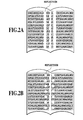
- the light sources 102 and 118 have a rod-like shape like a xenon tube, and becomes in a state where white spots are arranged as in FIG. 2B if the light sources 102 and 118 have a point-like shape like LED.
- both of the above-mentioned cases are reflection phenomena originating from the same principle, the state of reflection changes depending on the state of the shape of the sources 102 and 118 . If the light sources are point light sources, a problem in which unevenness of reflection occurs depending on a position is also present.
- An object of the present invention is to provide an image processing apparatus, an image processing method, and storage medium for reducing reflection effectively at low cost.
- An image processing apparatus includes: a selection unit selecting an RGB color component having minimum average values of each RGB color component among RGB color components of a read image having reflection of a light source that occurs when a document is read; a calculation unit calculating the amount of change of luminance values of pixels of the read image derived from the reflection, from the values of pixels of the color components selected in the read image; and a correction unit correcting the reflection of the light source in the read image by correcting the luminance values of pixels of the read image using the calculated amount of change of the luminance values of the pixels.
- an image processing apparatus an image processing method, and storage medium for reducing reflection effectively at low cost can be provided.
- FIG. 1 is a conceptual view illustrating one exemplary configuration of an image processing apparatus according to the present embodiment
- FIG. 2A is a schematic view of one example of a read image having reflection
- FIG. 2B is a schematic view of one example of a read image having reflection
- FIG. 3A is a conceptual view illustrating one example of the mechanism of reflection
- FIG. 3B is a conceptual view illustrating one example of the mechanism of reflection
- FIG. 4 is a block diagram illustrating one exemplary configuration of an image processing apparatus according to the present embodiment
- FIG. 5 is a flowchart illustrating one example of processing according to one embodiment
- FIG. 6 is a schematic view of one example of division into bands
- FIG. 7 is a schematic view illustrating one example of corresponding data when creating a color conversion table
- FIG. 8A is a schematic view illustrating one example of an input image or an output image in processing according to one embodiment
- FIG. 8B is a schematic view illustrating one example of an input image or an output image in processing according to one embodiment
- FIG. 8C is a schematic view illustrating one example of an input image or an output image in processing according to one embodiment
- FIG. 9 is a flowchart illustrating another example of processing according to one embodiment.
- FIG. 10 is a flowchart illustrating further another example of processing according to one embodiment.
- FIG. 11 illustrates one example of a one-dimensional conversion table made based on the luminance value according to one embodiment.
- the present embodiment is characterized in that reflection of light source occurring when a book manuscript is read is reduced using image processing by software (execution of a program) without changing a device. However, it is required that a certain level of information of the image of a reflection part is remained in the read image.
- FIG. 1 is a view illustrating one example of the mechanical configuration of an image processing apparatus according to the present invention.
- Light sources 102 and 118 , mirrors 103 , a lens 111 and a reading sensor 104 are stored in a reading device 110 .
- the light sources 102 and 118 After bringing the manuscript surface into contact with a platen 101 and giving instruction to start reading from a setting UI 108 , the light sources 102 and 118 emit light.
- the light sources 102 and 118 have spectral intensity in a wavelength region approximately within that of visible light.
- the manuscript is irradiated with light from the light sources 102 and 118 , and the light reflected on the manuscript is reflected by some reflection mirrors 103 , collected by the lens 111 , and then enters the reading sensor 104 .
- the reading sensor 104 includes at least a photoelectric conversion element, accumulates electric charges according to the intensity of the incident light, and converts the image information on the manuscript into digital image data by converting the electric charges into digital data using an A/D converter (not shown in the figure).
- the digital image data is processed in the controller 106 .
- FIG. 4 is a block diagram illustrating the minimum required configuration of an image processing apparatus.
- the image processing apparatus includes: a reading device 110 ; a setting UI 108 , an image processing section 401 ; CPU 402 ; a memory device 403 ; and RAM 404 , and they are connected each other by a bus 107 .
- the reading device 110 reads a manuscript and outputs the read image.
- the setting UI 108 is a user interface for a user to give various instructions such as start of reading to the image processing apparatus.
- the image processing section 401 receives data from other constituents via the bus 107 and performs various image processing.
- CPU 402 executes a program expanded in RAM 404 etc. to control image processing.
- the memory device 403 saves parameters required for image processing and image processing programs.
- the image processing section 401 , CPU 402 and RAM 404 are mounted on a controller 106 .
- anther necessary constituent such as an external I/F for connecting an external device (such as PC and a workstation) and an external line to this apparatus, may be added.
- FIG. 5 is a flowchart illustrating the flow of the processing of the present embodiment.
- the processing is performed by CPU 402 by steps of: reading a program stored on RAM 404 or the memory device 403 ; and executing the program to control each of the constituents of the image processing apparatus.
- the feature of the processing according to the present embodiment is in that an input image (the image read by the reading device 110 ) having reflection at least partially is divided into stripe-shaped band images (S 502 ) firstly; after that, the illumination light distribution of reflection is calculated for each band image by a specific channel (S 504 ); and the illumination light image is removed from a YCC converted luminance image 512 (S 506 ). As a result of this, influence of reflection can be reduced effectively.
- the input image 501 read by the reading device 110 is divided into band images. This processing is performed because it is desirable to remove extra pieces of information as many as possible in order to extract suitably the illumination light image of the reflection area in the below described processing.
- the input image 501 is temporarily stored on the memory device 403 , and read onto RAM 404 .
- Data of dividing direction and dividing number that is stored on the memory device 403 in advance is also read onto RAM 404 from the device 403 .
- the input image 501 is divided sequentially from its one end into band images 510 on RAM 404 . That is, the divided width of the band images 510 is determined depending on the divided number of the read image (the input image 501 ).
- the band images 510 are stored on the memory device 403 in order so that the position of each image in the entire input image 501 can be determined. Alternatively, they may be stored by being added with an index for each band.
- the start position of the next band is calculated by CPU 402 from the band width and the number of generated bands.
- FIG. 6 illustrates one example of a method for dividing an input image into band images.
- the dividing direction of the band images supposed to be in parallel with the direction in which reflection occurs.
- the read image is divided in the sub-scanning direction. It is desirable to optimally determine the dividing number depending on the reflection area, but, since position of reflection can not be specified, it is determined based on a projected size of reflection. If it is known that the width of the light source reflected on an image scanned with 600 dpi is an order of 40 pixels, it would be determined to divide the image into bands each having a width of at least 40 pixels or more.
- a method for dividing the image into bands may also be considered.
- a method for dividing the image into a fixed number of bands there is an advantage in that even if the resolution is changed, the image can be divided into bands without re-calculation.
- Step 505 of generating a luminance image 512 that will be used in later processing will be described.
- the input image 501 saved on the memory device 403 is read onto RAM 404 , and the read image is converted into a YCbCr luminance image 512 in the image processing section.
- the generated luminance image 512 is saved on the memory device 403 via the bus 107 .
- the above-mentioned processing is carried out for all of the band images 510 to be a target of removing reflection, and generation of the luminance image 512 (Step 505 ) will be finished.
- any one of the RGB color components is selected as the channel of a color component used for optimally extracting the illumination light image of the reflection area in the band image 510 that is a processing target.
- the illumination light image to be extracted is referred to as image data representing the change of an illumination component in the image.
- the band image 510 saved on the memory device 403 are read onto RAM 404 , the average values (average lightness) of RGB color components are calculated, respectively, and the calculated values are held on the memory device 403 .
- the calculated average values (average lightness) of all of RGB color components are compared, and a color component having the lowest (minimum) lightness value is selected and it is output to the image processing section 401 via the bus 107 together with the band image 510 .
- the selected color component (channel) is used for extracting only the illumination light image as much as possible when the image is extracted from the reflection area by the below described processing. It is considered that all channels of RGB have relatively large lightness values in the reflection area that is whitish than the surroundings, on the contrary, in areas other than the reflection area, it is considered that lightness differs largely for each channel.
- an image has, for example, a reddish (R) color at areas other than the reflection area, since the lightness of the R channel has a high value at areas other than the reflection area, it will be difficult to extract only the illumination light image in the reflection area using the R channel.
- the lightness of the blue (B) channel since the lightness of the blue (B) channel has a relatively large value only in the reflection area, if it has a small value in areas other than the reflection area, it is effective to extract the illumination light image using the B channel. Since, a channel where lightness of image data is changed largely by reflection is the channel of a color component having low lightness. That is, it is effective to extract the illumination light image using a channel having a lowest average lightness value. Moreover, although if this processing is performed to the entire input image, extra color information of the surroundings is also added, effective channel selection can be performed by dividing the input image into band images and performing this processing at a limited area.
- two channels maybe selected in ascending order of their average lightness values.
- two channels may be selected in ascending order of their average lightness values only when difference between the maximum value and the minimum value of the lightness of the RGB channels is equal to or smaller than a given value (for example; 50). This is because it is more effective to use two channels for extracting the illumination light image than using one channel.
- the illumination light image is extracted (i.e.; generated) from the channel selected at Step 503 .
- the image processing section 401 performs filtering processing on the selected channel of the band images 510 expanded on RAM 403 and calculates the illumination light distribution to extract the illumination light image.
- the extracted illumination light image 511 is sent to the memory device 403 via the bus 107 and saved thereon.
- the illumination light image can be grasped the low frequency components in an image as the change of illumination.
- Methods for extracting the illumination light image includes a method for performing convolution operation by a Gaussian filter on surrounding pixels including an attention pixel (x, y), and a method for performing convolution operation by a bilateral filter.
- the illumination light image is an image representing the amount of the change in luminance values due to reflection of the light source occurring when a manuscript is read. If there is no reflection of the light source, the illumination light image will be a black image having a luminance value of zero.
- the filtering processing may be performed after down-sampling the pixels so that the relative filter size can be larger even for a small filter size. As mentioned above, since the width of reflection is determined to some extent depending on the size of the light source, a filter will be used in estimation of its optimal size.
- Vs(x, y) Vc ( x, y )* G ( x, y )
- K represents a level of Gaussian function
- ⁇ represents the standard deviation of Gaussian function
- the reflected illumination light is removed (corrected).
- This step acts as a correction unit of reflection.
- the reflected illumination light is removed using the illumination light image 511 and the luminance image 512 saved on the memory device 403 .
- the illumination light image 511 and the luminance image 512 of the same band are read from the memory device 403 , and the image processing section 401 subtracts the lightness value of the illumination light image 511 from the luminance value of the luminance image 512 for each pixel.
- the illumination light image 511 is an RGB image. That is, using the extent of lightness brightened by reflection represented for each position by the illumination light image 511 as a correction amount, the luminance value for each position of the luminance image 512 is corrected.
- An advantage of adjusting the luminance value is in that only the brightness of an image can be changed without losing the color balance of the image.
- FIG. 8A represents an input image 501 having reflection
- the illumination light image as illustrated in FIG. 8B is extracted by the above-mentioned processing.
- the illumination light image extracted by the selected channel represents the area brightened by reflection and the level of the brightened lightness.
- Subtracting the lightness value of the illumination light image from the luminance value of the reflected image enables the lightness of an area where the lightness is read to be bright more than necessary by the influence of reflection to return a suitable level substantially without changing the lightness values of areas other than the reflected area.
- An image as illustrated in FIG. 8C where the influence of reflection is reduced, can be obtained as the output image 509 .
- the luminance value of the input image 501 is converted from RGB into YCbCr in advance.
- the luminance value may be obtained by converting RGB into L*a*b*.
- an image where reflection is removed is generated by mating a Y channel where the illumination light is removed and CbCr channels of a luminance image 512 where no change is imparted and then converting the resultant YCbCr channels into RGB channels.
- a correction method for reducing the difference in color between bands in the post processing at Step 508 will be described below.
- a correction table is created. Since the luminance value or the RGB values of the neighboring pixels between bands as illustrated in FIG. 7 are considered to be substantially the same each other, a one-dimensional or a three-dimensional color conversion table is created from the luminance value or the RGB values of the neighboring pixels.
- interpolation for example; linear interpolation
- a color conversion table is created and saved on the memory device 403 .
- a band image 510 to be a target and a band image 510 to be corrected are read onto RAM 404 from the memory device 403 .
- the band image 510 to be a target is, for example, band 1 in FIG. 7 that is a band image 510 located at a farthest point of the input image 501 .
- the band image 510 to be corrected is, for example, band 2 in FIG. 7 that is a band image 510 neighboring the band image 510 to be a target and not subjected to reflection correction.
- FIG. 11 one example of a one-dimensional conversion table created based on the luminance value will be described. All relationships in luminance values of the neighboring pixels between band 1 and band 2 in FIG. 7 are extracted and plotted on a graph.
- band 1 The luminance values in band 1 are reduced as a whole due to the reflection correction processing, on the contrary, band 2 is not subjected to correction, and thereby a conversion table is created, where the following relation is satisfied: the range of luminance values before correction ⁇ the range of luminance values after correction.
- the band image 510 to be corrected is scanned from its one end, and a value corresponding to the read pixel value is retrieved from the created color conversion table. Then, the read pixel value is corrected to the value obtained from the retrieval. If there is no data coinciding with the pixel value in the table, the correction value is calculated by an interpolation operation from data of surroundings. Moreover, it is possible to create a three-dimensional conversion table from the RGB values of the band images and to use it as the color conversion table.
- the bands are processed in a manner where bands neighboring to the both ends are subjected to correction using the both end bands as targets, and then next neighboring bands are subjected to correction using the corrected bands as targets, and so on. Since the bands of the both ends are still the input images, not only step difference in color between bands is reduced, but also the color of the processed bands approaches to that of the input image 501 . By the above-mentioned processing, an output image 509 where reflection is removed can be obtained.
- reflection of the light source occurring when a book manuscript is read, can be corrected by executing a program, that is, by image processing by means of software.
- reflection correction can be achieved at a lower cost.
- correction since correction is performed for each image area at a different correction amount based on the illumination light distribution extracted from the band images obtained by dividing the input image, effective reflection correction can be achieved regardless of the type of the light source. This enables generalized reflection correction to be achieved.
- the optimal dividing width of bands can be estimated from the size of the reflected light source. However, if magnification is specified during reading, the read image will be enlarged or shrunk. In this case, since the size of the reflected area will also change, the dividing width of bands has to be adjusted according to the magnification ratio of the read image.
- the magnification ratio set in the setting UI 109 is acquired. If the acquired magnification ration is not one, the read image is enlarged or shrunk.
- the dividing width of bands saved on the memory device 403 in advance is read and multiplied with the acquired magnification ratio, and the resultant value is used as the dividing width of bands at the magnification.
- the new dividing width of bands may be saved on RAM 404 so as to be directly used for the subsequent processing, or may be saved on the memory device 403 as a new dividing width of bands at magnification. If specified magnification ratios are selected in several kinds, correspondence relationship between the magnification ratio and the dividing width of bands maybe saved on the memory device 403 as a table.
- reflection can be removed even when a manuscript is read at setting of magnification.
- a channel for extracting an illumination light image when a channel for extracting an illumination light image is selected, by calculating average values of each channel in the band, and a channel having a lowest value is selected as the optimal channel for extracting the illumination light image.
- every channel has a large value in case of a high luminance image, that is, it is difficult to extract only the illumination light image.
- difference in luminance between the reflected high luminance area and the high luminance area in the manuscript is small in case of a high luminance image. That is, the influence of reflection tends to be not notable for a high luminance image than for a low luminance image. Therefore, in some cases, the influence of image change derived by removal of reflection may give odd feeling to a user than the influence of reflection.
- FIG. 9 illustrates a flow of processing according to the present embodiment.
- a given threshold value for determination (for example; luminance value of 200) is saved on the memory device 403 in advance as the threshold value for determining high luminance.
- the average lightness value of the selected channel and the threshold value for determining high luminance is compared.
- the band can be determined as a high luminance image, thereby, the subsequent processing (S 504 and S 506 ) will be eliminated, and if the average lightness value is lower than the threshold value, processing of S 504 and subsequent processing will be performed as usual.
- the threshold value of correction amount is referred to as a threshold value of the variation of a luminance value being in such a level that the change of color is not notable if the luminance value is changed, for example, a value such as 20 in 255 gradations can be considered.
- a method for changing the threshold value of correction amount by changing the kind and glossiness etc. of a paper is also possible.
- FIG. 10 illustrates a flow of processing according to the present embodiment.
- the threshold value of correction amount 1002 is saved on the memory device 403 in advance.
- Step 506 of removal processing of illumination light using the illumination light image 511 correction greater than the threshold value of correction amount 1002 will not be performed.
- a method for performing operation of rounding the pixel values of the illumination light image 511 greater than the threshold value of correction amount 1002 during subtracting the illumination light image 511 from the luminance image 512 at Step 506 can also be considered.
- aspects of the present invention can also be realized by a computer of a system or apparatus (or devices such as a CPU or MPU) that reads out and executes a program recorded on a memory device to perform the functions of the above-described embodiment(s), and by a method, the steps of which are performed by a computer of a system or apparatus by, for example, reading out and executing a program recorded on a memory device to perform the functions of the above-described embodiment(s).
- the program is provided to the computer for example via a network or from a recording medium of various types serving as the memory device (e.g., computer-readable medium).
Applications Claiming Priority (2)
| Application Number | Priority Date | Filing Date | Title |
|---|---|---|---|
| JP2008280060A JP5067886B2 (ja) | 2008-10-30 | 2008-10-30 | 画像処理装置及び画像処理方法 |
| JP2008-280060 | 2008-10-30 |
Publications (2)
| Publication Number | Publication Date |
|---|---|
| US20100111407A1 US20100111407A1 (en) | 2010-05-06 |
| US8224083B2 true US8224083B2 (en) | 2012-07-17 |
Family
ID=42131474
Family Applications (1)
| Application Number | Title | Priority Date | Filing Date |
|---|---|---|---|
| US12/579,916 Expired - Fee Related US8224083B2 (en) | 2008-10-30 | 2009-10-15 | Extraction of illumination light image in an image processing apparatus, and image processing method and storage medium therefor |
Country Status (2)
| Country | Link |
|---|---|
| US (1) | US8224083B2 (ja) |
| JP (1) | JP5067886B2 (ja) |
Cited By (1)
| Publication number | Priority date | Publication date | Assignee | Title |
|---|---|---|---|---|
| US20150156390A1 (en) * | 2013-12-04 | 2015-06-04 | Chung-Shan Institute Of Science And Technology, Armaments Bureau, M.N.D | Method for controlling reflectivity in imaging system |
Families Citing this family (6)
| Publication number | Priority date | Publication date | Assignee | Title |
|---|---|---|---|---|
| JP5067886B2 (ja) * | 2008-10-30 | 2012-11-07 | キヤノン株式会社 | 画像処理装置及び画像処理方法 |
| CN102867295B (zh) * | 2012-08-06 | 2015-10-21 | 电子科技大学 | 一种彩色图像颜色校正方法 |
| US20160210746A1 (en) * | 2013-10-01 | 2016-07-21 | Konica Minolta, Inc. | Organ imaging device |
| JP6433384B2 (ja) * | 2015-07-01 | 2018-12-05 | キヤノン株式会社 | 画像処理装置および画像処理方法 |
| CN112102182B (zh) * | 2020-08-31 | 2022-09-20 | 华南理工大学 | 一种基于深度学习的单图像去反射方法 |
| CN113221763B (zh) * | 2021-05-18 | 2024-04-16 | 东南大学 | 一种基于视频图像亮度的火焰识别方法 |
Citations (10)
| Publication number | Priority date | Publication date | Assignee | Title |
|---|---|---|---|---|
| JPH05127265A (ja) | 1991-11-06 | 1993-05-25 | Sharp Corp | 電子写真装置の露光装置 |
| US5517333A (en) * | 1993-02-24 | 1996-05-14 | Matsushita Electric Industrial Co., Ltd. | Gradation correction device and image sensing device therewith for supplying images with good gradation for both front-lit and back-lit objects |
| JP2001223850A (ja) | 2000-02-10 | 2001-08-17 | Fuji Xerox Co Ltd | 画像読取装置 |
| US20010035988A1 (en) * | 2000-04-14 | 2001-11-01 | Satoshi Semba | Color image processing apparatus and method, and computer- readable recording medium in which color image processing program is recorded |
| US20030002059A1 (en) * | 2001-07-02 | 2003-01-02 | Jasc Software, Inc. | Automatic color balance |
| US20030151694A1 (en) * | 2002-02-08 | 2003-08-14 | Samsung Electronics Co., Ltd. | Method and apparatus for changing brightness of image |
| US6664973B1 (en) * | 1996-04-28 | 2003-12-16 | Fujitsu Limited | Image processing apparatus, method for processing and image and computer-readable recording medium for causing a computer to process images |
| US20090052774A1 (en) * | 2005-03-25 | 2009-02-26 | Hideki Yoshii | Image processing apparatus, image display apparatus, and image display method |
| US7612824B2 (en) * | 2002-07-19 | 2009-11-03 | Seiko Epson Corporation | Image-quality adjustment of image data |
| US20100111407A1 (en) * | 2008-10-30 | 2010-05-06 | Canon Kabushiki Kaisha | Image processing apparatus, image processing method and storage medium |
Family Cites Families (1)
| Publication number | Priority date | Publication date | Assignee | Title |
|---|---|---|---|---|
| JPH1093778A (ja) * | 1996-09-19 | 1998-04-10 | Minolta Co Ltd | 画像読取り装置 |
-
2008
- 2008-10-30 JP JP2008280060A patent/JP5067886B2/ja not_active Expired - Fee Related
-
2009
- 2009-10-15 US US12/579,916 patent/US8224083B2/en not_active Expired - Fee Related
Patent Citations (10)
| Publication number | Priority date | Publication date | Assignee | Title |
|---|---|---|---|---|
| JPH05127265A (ja) | 1991-11-06 | 1993-05-25 | Sharp Corp | 電子写真装置の露光装置 |
| US5517333A (en) * | 1993-02-24 | 1996-05-14 | Matsushita Electric Industrial Co., Ltd. | Gradation correction device and image sensing device therewith for supplying images with good gradation for both front-lit and back-lit objects |
| US6664973B1 (en) * | 1996-04-28 | 2003-12-16 | Fujitsu Limited | Image processing apparatus, method for processing and image and computer-readable recording medium for causing a computer to process images |
| JP2001223850A (ja) | 2000-02-10 | 2001-08-17 | Fuji Xerox Co Ltd | 画像読取装置 |
| US20010035988A1 (en) * | 2000-04-14 | 2001-11-01 | Satoshi Semba | Color image processing apparatus and method, and computer- readable recording medium in which color image processing program is recorded |
| US20030002059A1 (en) * | 2001-07-02 | 2003-01-02 | Jasc Software, Inc. | Automatic color balance |
| US20030151694A1 (en) * | 2002-02-08 | 2003-08-14 | Samsung Electronics Co., Ltd. | Method and apparatus for changing brightness of image |
| US7612824B2 (en) * | 2002-07-19 | 2009-11-03 | Seiko Epson Corporation | Image-quality adjustment of image data |
| US20090052774A1 (en) * | 2005-03-25 | 2009-02-26 | Hideki Yoshii | Image processing apparatus, image display apparatus, and image display method |
| US20100111407A1 (en) * | 2008-10-30 | 2010-05-06 | Canon Kabushiki Kaisha | Image processing apparatus, image processing method and storage medium |
Cited By (2)
| Publication number | Priority date | Publication date | Assignee | Title |
|---|---|---|---|---|
| US20150156390A1 (en) * | 2013-12-04 | 2015-06-04 | Chung-Shan Institute Of Science And Technology, Armaments Bureau, M.N.D | Method for controlling reflectivity in imaging system |
| US9191577B2 (en) * | 2013-12-04 | 2015-11-17 | National Chung Institute Of Science And Technology | Method for controlling reflectivity in imaging system |
Also Published As
| Publication number | Publication date |
|---|---|
| US20100111407A1 (en) | 2010-05-06 |
| JP2010109723A (ja) | 2010-05-13 |
| JP5067886B2 (ja) | 2012-11-07 |
Similar Documents
| Publication | Publication Date | Title |
|---|---|---|
| US8224083B2 (en) | Extraction of illumination light image in an image processing apparatus, and image processing method and storage medium therefor | |
| US5850298A (en) | Image processing device eliminating background noise | |
| US8243333B2 (en) | Image processing apparatus, image processing method and computer program | |
| US8391646B2 (en) | Image processing device and method that performs image quality adjustment and resize processing on image data | |
| US7586653B2 (en) | Method and system for enhancing an image using luminance scaling | |
| CN108513039B (zh) | 图像处理装置、图像处理方法及记录介质 | |
| JP3477858B2 (ja) | 画像処理装置及び画像データ処理方法 | |
| US8290293B2 (en) | Image compensation in regions of low image contrast | |
| US20230045024A1 (en) | Information processing apparatus, method, and computer-readable medium | |
| US9160868B2 (en) | Document reading apparatus, document reading method and storage medium | |
| JP4222230B2 (ja) | 画像読取装置、画像形成装置、画像処理装置、およびプログラム | |
| JP4024737B2 (ja) | 画像処理装置、画像読取装置、画像形成装置、画像処理方法、およびプログラム | |
| JP7391653B2 (ja) | 画像処理装置、画像処理方法、及びプログラム | |
| JP4933418B2 (ja) | 画像読取装置、マルチファンクションプリンタ装置、及び画像処理方法 | |
| JP2005173926A (ja) | 画像処理装置、方法、プログラム及び記憶媒体 | |
| CN111738960A (zh) | 图像处理设备、方法及图像形成装置 | |
| JP7135575B2 (ja) | 画像処理装置、画像読取装置及びプログラム | |
| JP2005027110A (ja) | 画像処理装置及びそれを備えた画像読取装置、画像形成装置、並びに画像処理方法、画像処理プログラム及び記録媒体 | |
| JP2005176168A (ja) | 画像処理装置 | |
| JP4328608B2 (ja) | 画像処理装置、方法、プログラム及び記憶媒体 | |
| JP2008252772A (ja) | 画像処理装置および画像処理プログラム | |
| JP3729131B2 (ja) | 画像形成装置 | |
| JP4277778B2 (ja) | 画像読取装置 | |
| JPH08186728A (ja) | 画像処理装置 | |
| JP4328609B2 (ja) | 画像処理装置、方法、プログラム及び記憶媒体 |
Legal Events
| Date | Code | Title | Description |
|---|---|---|---|
| AS | Assignment |
Owner name: CANON KABUSHIKI KAISHA,JAPAN Free format text: ASSIGNMENT OF ASSIGNORS INTEREST;ASSIGNOR:HASHIZUME, ASAKO;REEL/FRAME:023836/0909 Effective date: 20090930 Owner name: CANON KABUSHIKI KAISHA, JAPAN Free format text: ASSIGNMENT OF ASSIGNORS INTEREST;ASSIGNOR:HASHIZUME, ASAKO;REEL/FRAME:023836/0909 Effective date: 20090930 |
|
| STCF | Information on status: patent grant |
Free format text: PATENTED CASE |
|
| FEPP | Fee payment procedure |
Free format text: PAYOR NUMBER ASSIGNED (ORIGINAL EVENT CODE: ASPN); ENTITY STATUS OF PATENT OWNER: LARGE ENTITY |
|
| FPAY | Fee payment |
Year of fee payment: 4 |
|
| FEPP | Fee payment procedure |
Free format text: MAINTENANCE FEE REMINDER MAILED (ORIGINAL EVENT CODE: REM.); ENTITY STATUS OF PATENT OWNER: LARGE ENTITY |
|
| LAPS | Lapse for failure to pay maintenance fees |
Free format text: PATENT EXPIRED FOR FAILURE TO PAY MAINTENANCE FEES (ORIGINAL EVENT CODE: EXP.); ENTITY STATUS OF PATENT OWNER: LARGE ENTITY |
|
| STCH | Information on status: patent discontinuation |
Free format text: PATENT EXPIRED DUE TO NONPAYMENT OF MAINTENANCE FEES UNDER 37 CFR 1.362 |
|
| FP | Lapsed due to failure to pay maintenance fee |
Effective date: 20200717 |