US8215878B2 - Indirect cooling of a rotary cutting tool - Google Patents
Indirect cooling of a rotary cutting tool Download PDFInfo
- Publication number
- US8215878B2 US8215878B2 US12/428,201 US42820109A US8215878B2 US 8215878 B2 US8215878 B2 US 8215878B2 US 42820109 A US42820109 A US 42820109A US 8215878 B2 US8215878 B2 US 8215878B2
- Authority
- US
- United States
- Prior art keywords
- coolant
- tool
- cutting
- indirect cooling
- insert
- Prior art date
- Legal status (The legal status is an assumption and is not a legal conclusion. Google has not performed a legal analysis and makes no representation as to the accuracy of the status listed.)
- Active, expires
Links
Images


Classifications
-
- B—PERFORMING OPERATIONS; TRANSPORTING
- B23—MACHINE TOOLS; METAL-WORKING NOT OTHERWISE PROVIDED FOR
- B23C—MILLING
- B23C5/00—Milling-cutters
- B23C5/28—Features relating to lubricating or cooling
- B23C5/283—Cutting inserts with internal coolant channels
-
- B—PERFORMING OPERATIONS; TRANSPORTING
- B23—MACHINE TOOLS; METAL-WORKING NOT OTHERWISE PROVIDED FOR
- B23C—MILLING
- B23C5/00—Milling-cutters
- B23C5/16—Milling-cutters characterised by physical features other than shape
- B23C5/20—Milling-cutters characterised by physical features other than shape with removable cutter bits or teeth or cutting inserts
- B23C5/202—Plate-like cutting inserts with special form
-
- B—PERFORMING OPERATIONS; TRANSPORTING
- B23—MACHINE TOOLS; METAL-WORKING NOT OTHERWISE PROVIDED FOR
- B23Q—DETAILS, COMPONENTS, OR ACCESSORIES FOR MACHINE TOOLS, e.g. ARRANGEMENTS FOR COPYING OR CONTROLLING; MACHINE TOOLS IN GENERAL CHARACTERISED BY THE CONSTRUCTION OF PARTICULAR DETAILS OR COMPONENTS; COMBINATIONS OR ASSOCIATIONS OF METAL-WORKING MACHINES, NOT DIRECTED TO A PARTICULAR RESULT
- B23Q11/00—Accessories fitted to machine tools for keeping tools or parts of the machine in good working condition or for cooling work; Safety devices specially combined with or arranged in, or specially adapted for use in connection with, machine tools
- B23Q11/10—Arrangements for cooling or lubricating tools or work
- B23Q11/1038—Arrangements for cooling or lubricating tools or work using cutting liquids with special characteristics, e.g. flow rate, quality
- B23Q11/1046—Arrangements for cooling or lubricating tools or work using cutting liquids with special characteristics, e.g. flow rate, quality using a minimal quantity of lubricant
-
- B—PERFORMING OPERATIONS; TRANSPORTING
- B23—MACHINE TOOLS; METAL-WORKING NOT OTHERWISE PROVIDED FOR
- B23Q—DETAILS, COMPONENTS, OR ACCESSORIES FOR MACHINE TOOLS, e.g. ARRANGEMENTS FOR COPYING OR CONTROLLING; MACHINE TOOLS IN GENERAL CHARACTERISED BY THE CONSTRUCTION OF PARTICULAR DETAILS OR COMPONENTS; COMBINATIONS OR ASSOCIATIONS OF METAL-WORKING MACHINES, NOT DIRECTED TO A PARTICULAR RESULT
- B23Q11/00—Accessories fitted to machine tools for keeping tools or parts of the machine in good working condition or for cooling work; Safety devices specially combined with or arranged in, or specially adapted for use in connection with, machine tools
- B23Q11/10—Arrangements for cooling or lubricating tools or work
- B23Q11/1038—Arrangements for cooling or lubricating tools or work using cutting liquids with special characteristics, e.g. flow rate, quality
- B23Q11/1061—Arrangements for cooling or lubricating tools or work using cutting liquids with special characteristics, e.g. flow rate, quality using cutting liquids with specially selected composition or state of aggregation
-
- B—PERFORMING OPERATIONS; TRANSPORTING
- B23—MACHINE TOOLS; METAL-WORKING NOT OTHERWISE PROVIDED FOR
- B23C—MILLING
- B23C2200/00—Details of milling cutting inserts
- B23C2200/16—Supporting or bottom surfaces
- B23C2200/165—Supporting or bottom surfaces with one or more grooves
-
- Y—GENERAL TAGGING OF NEW TECHNOLOGICAL DEVELOPMENTS; GENERAL TAGGING OF CROSS-SECTIONAL TECHNOLOGIES SPANNING OVER SEVERAL SECTIONS OF THE IPC; TECHNICAL SUBJECTS COVERED BY FORMER USPC CROSS-REFERENCE ART COLLECTIONS [XRACs] AND DIGESTS
- Y02—TECHNOLOGIES OR APPLICATIONS FOR MITIGATION OR ADAPTATION AGAINST CLIMATE CHANGE
- Y02P—CLIMATE CHANGE MITIGATION TECHNOLOGIES IN THE PRODUCTION OR PROCESSING OF GOODS
- Y02P70/00—Climate change mitigation technologies in the production process for final industrial or consumer products
- Y02P70/10—Greenhouse gas [GHG] capture, material saving, heat recovery or other energy efficient measures, e.g. motor control, characterised by manufacturing processes, e.g. for rolling metal or metal working
-
- Y—GENERAL TAGGING OF NEW TECHNOLOGICAL DEVELOPMENTS; GENERAL TAGGING OF CROSS-SECTIONAL TECHNOLOGIES SPANNING OVER SEVERAL SECTIONS OF THE IPC; TECHNICAL SUBJECTS COVERED BY FORMER USPC CROSS-REFERENCE ART COLLECTIONS [XRACs] AND DIGESTS
- Y10—TECHNICAL SUBJECTS COVERED BY FORMER USPC
- Y10T—TECHNICAL SUBJECTS COVERED BY FORMER US CLASSIFICATION
- Y10T407/00—Cutters, for shaping
- Y10T407/11—Cutters, for shaping including chip breaker, guide or deflector detachable from tool and tool holder
- Y10T407/118—Chip breaker
-
- Y—GENERAL TAGGING OF NEW TECHNOLOGICAL DEVELOPMENTS; GENERAL TAGGING OF CROSS-SECTIONAL TECHNOLOGIES SPANNING OVER SEVERAL SECTIONS OF THE IPC; TECHNICAL SUBJECTS COVERED BY FORMER USPC CROSS-REFERENCE ART COLLECTIONS [XRACs] AND DIGESTS
- Y10—TECHNICAL SUBJECTS COVERED BY FORMER USPC
- Y10T—TECHNICAL SUBJECTS COVERED BY FORMER US CLASSIFICATION
- Y10T407/00—Cutters, for shaping
- Y10T407/14—Cutters, for shaping with means to apply fluid to cutting tool
-
- Y—GENERAL TAGGING OF NEW TECHNOLOGICAL DEVELOPMENTS; GENERAL TAGGING OF CROSS-SECTIONAL TECHNOLOGIES SPANNING OVER SEVERAL SECTIONS OF THE IPC; TECHNICAL SUBJECTS COVERED BY FORMER USPC CROSS-REFERENCE ART COLLECTIONS [XRACs] AND DIGESTS
- Y10—TECHNICAL SUBJECTS COVERED BY FORMER USPC
- Y10T—TECHNICAL SUBJECTS COVERED BY FORMER US CLASSIFICATION
- Y10T408/00—Cutting by use of rotating axially moving tool
- Y10T408/44—Cutting by use of rotating axially moving tool with means to apply transient, fluent medium to work or product
Definitions
- a cooling system for the tool-chip interface of a rotary cutting tool uses both indirect and direct cooling of the cutter edge by a cryogenic fluid to enable the high-speed machining of titanium alloys and other advanced materials with low thermal conductivity.
- Cutting fluids have been used in machining processes for many years to increase lubricity by spraying the coolant into the machining zone directly on the cutting tool and the workpiece. This has the effect of decreasing the friction between the chip and the tool, which in turn decreases the tool temperature, increases tool life, and improves the part quality. These benefits come with certain drawbacks. In high-volume machining operations, at least 16% of the machining cost is associated with the procurement, maintenance, and disposal of cutting fluids. This cost does not account for the health risks workers are exposed to when using these fluids. Contact with cutting fluids or their mists can cause maladies such as dermatitis and respiratory diseases. Some additives in cutting fluids may be carcinogenic.
- Past research efforts and patents have focused on internally or externally cooling the cutting tool holder, spraying liquid nitrogen into the machining zone, using high-pressure coolants, and the integration of a cap-like reservoir on top of the cutting tool insert that is cooled by liquid nitrogen.
- cryogenic fluid refers to a liquid, such as liquid nitrogen (LN 2 ), that boils at a temperature below about 110 K ( ⁇ 160° C.) and is used to obtain very low temperatures.
- LN 2 liquid nitrogen
- the main benefit of using a cryogenic liquid in this application is the use of the latent heat of vaporization of the cryogen as a means to remove heat from the tool-chip interface. As opposed to sensible heat transfer, where any heat gain by a single-phase fluid is accompanied by a temperature rise; latent heat transfer uses the isothermal phase change from a saturated liquid to vapor as a means to absorb heat.
- the amount of cryogen needed for effective cooling is a function of the heat transfer rate to the tool during machining.
- the volumetric heat generation, q m , associated with a machining operation is expressed as;
- q ′′′ ⁇ V ⁇ ⁇ V ⁇ ⁇ . ⁇ ⁇ _ ⁇ d V
- ⁇ dot over ( ⁇ ) ⁇ , ⁇ , and V are the strain rate during machining, the material flow stress, and the volume of the strained material, known as the primary shear zone, respectively.
- the constant ⁇ represents the fraction of the deformation energy that is dissipated as sensible heating. For metals, the value of this constant is 0.8 or higher.
- the energy generated in the primary shear zone can be manifested as heating of the eventual chip after machining or be transferred to the tool.
- the fraction of heat flowing into the tool is a function of the tool geometry, the material, the machining conditions, and other variables.
- the cryogen is delivered from a fixed source, through a vacuum-insulated tube, and through other hardware mounted within the machine tool spindle, prior to reaching the tool.
- the cryogen is at a saturated condition as it leaves the source and flows toward the tool.
- a saturated condition means that any input of heat to the cryogen as it flows will result in the vaporization of some of the liquid to vapor.
- a key element of the components that are upstream of the tool itself is the minimization of heat transfer into the cryogen from the environment, also known as the heat leak into the cryogen.
- the heat leak can never be made to be zero; hence the flow after it leaves the source is known as a two-phase flow, where liquid and gas exist simultaneously. Minimizing the heat leak into the cryogen maximizes the liquid fraction in the two-phase flow, increases the amount of latent heat transfer at the cutter edge, and reduces the overall flow rates needed for effective cooling.
- the cryogen is delivered to channels machined within a rotary tool holder to facilitate the effective heat removal from the cutting edge.
- the cryogen travels through these channels to a cavity formed on the back surface of the cutter element, enabling effective cooling near the cutting edge of the element. Because the total flow rate of the cryogen is low (less than 0.08 Liters/min/cutting edge), the fluid can be safely vented to atmosphere from the cavity in the back of the insert, and as a result, no specialized coolant recovery or ventilation equipment is needed. Based on present estimates, up to 0.07 L/min/cutting edge is used for latent heat transfer, while 0.1 L/min/cutting edge absorbs upstream heat leaks. The vapor quality of the two-phase flow entering the cutting edge is therefore approximately 0.13.
- cryogen will be used to describe the coolant flow through the tool.
- cryogen is understood to be a two-phase flow.
- the invention is designed to be used with standard end mills and other rotary cutting tools; and as a result, it can be easily integrated with current manufacturing operations.
- FIG. 1 is a detail view of the working end of an end mill and a cutting tool insert.
- FIG. 2 shows the rear face of the insert shown in FIG. 1 .
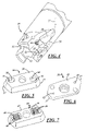
- FIG. 3 shows an end mill having both direct and indirect cryogen cooling of the tool-chip interface.
- FIG. 4 shows the end mill of FIG. 3 with the inserts removed.
- FIGS. 5 and 6 are back and front views, respectively, of an insert with cavities for receiving a cryogen.
- FIG. 7 is a back view of an insert with cavities having integrally formed fins.
- FIG. 8 is a graph showing the effect of surface speed on tool life using different tool lubricating and cooling techniques.
- FIG. 9 is a graph showing tool life of a rotating tool.
- FIG. 1 shows the end of a rotary cutting tool, such as an end mill, generally designated by the reference numeral 10 .
- An insert 12 may be secured in a pocket 14 in the end of the tool body 11 by a screw 13 .
- the insert 12 has a cutting edge 15 that wraps around the corner of the insert.
- the particular milling cuter shown has two pockets 14 for receiving two inserts 12 that are disposed 180 degrees from one another, although end mills having pockets for receiving other numbers of inserts are well known in the art.
- fluted end mills that have no inserts but have integrally formed flutes for cutting the workpiece, or cutting elements that are brazed or otherwise attached to the cutter body, are also well known in the art.
- the indirect cooling system as described herein can apply to any rotating tool, with integral or attached cutting edges, or with inserts.
- the insert 12 is cooled indirectly by having cryogen applied to the rear face of the insert as described below.
- Cryogen is delivered to the rotary cutting tool 10 either through the spindle or by a rotary coolant holder (not shown) that couples to the tool holder in which the end mill 10 is mounted.
- a channel 17 is formed in the end mill 10 to deliver coolant to an outlet 18 in the pocket 14 so that the coolant can be delivered to the rear face 16 of the insert 12 .
- An exhaust outlet 19 is formed at the front of the insert 12 to allow vaporized cryogen (gas) to be vented to the atmosphere.
- FIG. 2 shows the back of the insert 12 of FIG. 1 .
- a cavity 21 is formed in the rear face 16 of the insert opposite the cutting edge 15 such as by electro-discharge machining (EDM), or other machining method.
- EDM electro-discharge machining
- the position of the cavity 21 on the rear face 16 delivers the cryogen in close proximity to the cutting edge 15 of the insert.
- the enhanced surface area created by the cavity 21 within the insert increases the heat transfer between the insert and the cryogen that is delivered to the cavity from the outlet 18 .
- An exhaust port 22 is formed in the cavity 21 that is in communication with the exhaust outlet 19 shown on the front of the insert.
- a cryogen is delivered through the channel 17 to the outlet 18 where it enters the cavity 21 formed in the rear face of the insert.
- the cryogen removes heat from the insert, and the heat removal is most pronounced in the region of the cutting edge 15 of the insert that is immediately adjacent to the outlet 18 where the cryogen enters the cavity 21 .
- Vaporized cryogen gas
- the flow of coolant that is required is approximately 0.08 L/min for each cutting edge compared with flood cooling using conventional coolant at a flow rate of 15 liters per minute.
- FIGS. 3 and 4 are detail views of an alternate embodiment of an endmill 25 showing cutting tool cooling through the use of both direct and indirect cooling ports.
- the endmill 25 has three pockets 32 for receiving three inserts 26 .
- the cryogen flows from a suitable source through an internal insulated channel 27 in the endmill 25 toward the cutting tip of the tool where the flow splits to form a direct cooling channel 28 and an indirect cooling channel 29 .
- the cooling channels for only one of the inserts 26 are shown, and similar channels are provided for the other inserts 26 .
- the direct cooling channel 28 terminates in a jet opening 31 on the endmill that is spaced from the insert 26 that sprays a stream 35 of cryogen directly onto the tool-chip interface.
- the indirect cooling channel 29 directs the coolant flow to an outlet 33 that is positioned in the tool pocket 32 to direct the coolant to the back surface of the insert 26 as described above in connection with FIGS. 1 and 2 .
- FIGS. 5 and 6 show the back 39 and the front 43 , respectively, of an insert 36 which has two cutting edges 37 , only one of which will be used at a time.
- the insert 36 has two generally rectangular cavities 38 formed in the rear surface 39 thereof. Each cavity 38 is positioned on the insert 36 to be closely adjacent to a cutting edge 37 to maximize the cooling effect of the cryogen that is applied to the back of the insert.
- An exhaust port 41 is formed in each cavity 38 on the rear face 39 of the insert that leads to an exhaust outlet 42 on the front face 43 of the insert as shown in FIG. 6 to vent warmed cryogen from the cavity 38 to atmosphere.
- FIG. 7 shows an alternative form of an insert 45 in which each cavity 46 formed in the rear face 47 of the insert includes integral fins 48 .
- the fins 48 provide increased surface area contact between the cryogen and the insert 45 to further enhance the heat transfer from the insert to the cryogen.
- Each cavity 46 includes an exhaust port (not shown) to allow cryogen to be vented to the atmosphere through an exhaust outlet formed on the front of the insert.
- Machining was performed using a rotating cutting tool with prior art flood cooling and a rotating cutting tool with inserts 12 using the indirect cooling system shown in FIGS. 1 and 2 .
- Each cutting tool configuration was used to machine four slots in succession in a test block of titanium.
- the inserts 12 were removed and examined for tool wear. The average extent of the flank wear scar was measured and the tool life was predicted using an industry standard of 0.3 mm of wear as the amount of wear that could be tolerated before the tool had to be replaced. This test shows a 478% increase in tool life for the indirect cooled insert as shown in FIGS. 1 and 2 compared to the flood cooled insert.
- the results of the tool life tests for a rotating tool with indirect cooling are plotted in FIG. 8 for the embodiment shown in FIGS. 3 and 4 .
- the tests were performed using a three insert one-inch end mill as shown in FIG. 3 cutting at 0.0625 depth of cut that is 1.0 inches wide.
- the plot shows that at surface speeds near 200 ft/min, the increase in tool life with a tool having indirect cooling of the inserts with a flow rate of 0.23 Liters/min (approximately 0.08 L/min/cutting edge for three edges) compared to a tool with conventional flood cooling requiring up to 15 Liters/min of standard synthetic coolant is similar to the increase in tool life shown in connection with the tool wear results given in Table 1 above.
- the residual stress distribution was measured using X-ray diffraction. Residual stress is an indicator of fatigue life.
- the results for the cutting tool with indirect insert cooling indicates that the indirect cooling has no negative influence on the residual stress distribution near the machined part surface or on the fatigue life of the part when compared to conventional flood cooling.
- a test block of titanium was machined to demonstrate the effectiveness of the embodiment shown in FIGS. 3 and 4 .
- the machining was performed on a block of mill annealed Ti6Al4V that is nominally 2.75 by 8 by 21 in. into which two parallel deep pockets were machined using a vertical CNC machining center.
- the pockets each have dimensions of 2.5 by 3.55 by 20.6 in.
- the purpose of this test was to demonstrate the performance of the indirectly cooled tool and to produce titanium fatigue test samples.
- the outside of the titanium block was skim cut on all six sides. During the demonstration, machining was performed using the indirectly cooled tool for 160 minutes (20 passes at 8 min each) prior to changing inserts.
- FIG. 9 shows that tool life of a rotating tool as shown in FIG. 3 with the indirect cooling system is nearly 600% longer than with conventional flood cooling.
- Tool life is calculated as the amount of machining time before reaching 0.3 mm average flank wear.
- the 0.3 mm flank wear measurement is consistent with Section 7 of ANSI/ASME B94.55M-1985 (Reaffirmed 1995) which defines industry accepted tool life criteria and tool wear measurements.
- FIG. 9 is a plot of average flank wear versus cutting time using standard inserts with flood cooling and modified inserts with the indirect cooling system.
- FIG. 9 shows that the modified inserts with the indirect cooling system have much less wear than unmodified inserts with standard flood coolant.
- the indirect cooling system with simple square cavity inserts are at 0.05-mm flank wear. Further machining using the indirect cooling system with simple square cavity inserts shows that after nine minutes, the indirect cooled inserts have reached only one half of the 0.3-mm flank wear life limit.
- the indirect cutting tool cooling system approach to machining titanium alloys substantially reduces the cutting tool temperature and, thereby, enables significant increases in processing speed.
- the indirect cutting tool cooling system greatly improves the marketability of titanium components and should result in an increase the use of titanium in other applications.
- the design directs cooling where it is needed most for the high-speed machining of titanium, i.e., the cutting edge. In doing so, indirect cooling as described reduces the temperature of the cutting tool, without unnecessarily cooling the part being machined. The net result is a dramatic improvement in processing speed, which significantly decreases processing costs.
Landscapes
- Engineering & Computer Science (AREA)
- Mechanical Engineering (AREA)
- Physics & Mathematics (AREA)
- Fluid Mechanics (AREA)
- Auxiliary Devices For Machine Tools (AREA)
- Turning (AREA)
- Milling Processes (AREA)
- Cutting Tools, Boring Holders, And Turrets (AREA)
Abstract
Description
where {dot over (ε)},
| TABLE 1 |
| Tool Wear Results from Titanium Machining |
| Experiments at a Surface Speed of 200 ft/min |
| Indirect Cutting Tool Cooling | Flood Cooling | ||
| Depth of Cut = 0.125 inch | Depth of Cut = 0.125 inch | ||
| ~0.16 L/min of LN2 | 15 L/min of Coolant | ||
| Tool Life = 18.5 minutes | Tool Life = 3.2 minutes | ||
Claims (9)
Priority Applications (11)
| Application Number | Priority Date | Filing Date | Title |
|---|---|---|---|
| US12/428,201 US8215878B2 (en) | 2009-04-22 | 2009-04-22 | Indirect cooling of a rotary cutting tool |
| CN201080018033.9A CN102427906B (en) | 2009-04-22 | 2010-04-21 | Indirect cooling of a rotary cutting tool |
| KR1020117027644A KR101360858B1 (en) | 2009-04-22 | 2010-04-21 | Indirect cooling of a rotary cutting tool |
| RU2011147224/02A RU2522401C2 (en) | 2009-04-22 | 2010-04-21 | Indirect cooling of rotary cutting tool |
| BRPI1013942-7A BRPI1013942B1 (en) | 2009-04-22 | 2010-04-21 | COOLING SYSTEM FOR A ROTATING TOOL |
| JP2012507347A JP5745503B2 (en) | 2009-04-22 | 2010-04-21 | Indirect cooling of rotary cutting tools |
| ES10786530.5T ES2536485T3 (en) | 2009-04-22 | 2010-04-21 | Cooling system for rotary tool |
| PCT/US2010/031884 WO2010144180A2 (en) | 2009-04-22 | 2010-04-21 | Indirect cooling of a rotary cutting tool |
| EP10786530.5A EP2421673B1 (en) | 2009-04-22 | 2010-04-21 | Cooling system for a rotating tool |
| CA2759710A CA2759710C (en) | 2009-04-22 | 2010-04-21 | Indirect cooling of a rotary cutting tool |
| IL215830A IL215830A (en) | 2009-04-22 | 2011-10-23 | Indirect cooling of rotary cutting tools |
Applications Claiming Priority (1)
| Application Number | Priority Date | Filing Date | Title |
|---|---|---|---|
| US12/428,201 US8215878B2 (en) | 2009-04-22 | 2009-04-22 | Indirect cooling of a rotary cutting tool |
Publications (2)
| Publication Number | Publication Date |
|---|---|
| US20100272529A1 US20100272529A1 (en) | 2010-10-28 |
| US8215878B2 true US8215878B2 (en) | 2012-07-10 |
Family
ID=42992287
Family Applications (1)
| Application Number | Title | Priority Date | Filing Date |
|---|---|---|---|
| US12/428,201 Active 2030-04-01 US8215878B2 (en) | 2009-04-22 | 2009-04-22 | Indirect cooling of a rotary cutting tool |
Country Status (11)
| Country | Link |
|---|---|
| US (1) | US8215878B2 (en) |
| EP (1) | EP2421673B1 (en) |
| JP (1) | JP5745503B2 (en) |
| KR (1) | KR101360858B1 (en) |
| CN (1) | CN102427906B (en) |
| BR (1) | BRPI1013942B1 (en) |
| CA (1) | CA2759710C (en) |
| ES (1) | ES2536485T3 (en) |
| IL (1) | IL215830A (en) |
| RU (1) | RU2522401C2 (en) |
| WO (1) | WO2010144180A2 (en) |
Cited By (19)
| Publication number | Priority date | Publication date | Assignee | Title |
|---|---|---|---|---|
| US20110020074A1 (en) * | 2007-01-18 | 2011-01-27 | Kennametal Inc. | Cutting inserts |
| US20110020073A1 (en) * | 2007-01-18 | 2011-01-27 | Kennametal Inc. | Cutting insert assembly and components thereof |
| US20110027021A1 (en) * | 2007-01-18 | 2011-02-03 | Kennametal Inc. | Cutting insert with internal coolant delivery and cutting assembly using the same |
| US20130129429A1 (en) * | 2011-11-23 | 2013-05-23 | Kennametal Inc. | Rotary cutting tool with coolant passage disposed in non-circular recess for reducing stress |
| US8596935B2 (en) | 2010-10-08 | 2013-12-03 | TDY Industries, LLC | Cutting tools and cutting inserts including internal cooling |
| CN103658795A (en) * | 2012-09-26 | 2014-03-26 | 深圳市中天精密工具有限公司 | Polycrystalline diamond milling cutter |
| US8727673B2 (en) | 2007-01-18 | 2014-05-20 | Kennametal Inc. | Cutting insert with internal coolant delivery and surface feature for enhanced coolant flow |
| US8827599B2 (en) | 2010-09-02 | 2014-09-09 | Kennametal Inc. | Cutting insert assembly and components thereof |
| US20140369772A1 (en) * | 2013-06-14 | 2014-12-18 | Kennametal Inc. | Cutting tool assembly having clamp assembly comprising a clamp and a coolant plate |
| US20150273597A1 (en) * | 2012-09-21 | 2015-10-01 | European Aeronautic Defence And Space Company Eads France | Drilling tool and device for drilling with cryogenic cooling and method for drilling a stack of heterogeneous materials |
| US9180650B2 (en) | 2010-10-08 | 2015-11-10 | Kennametal Inc. | Cutting tool including an internal coolant system and fastener for a cutting tool including an internal coolant system |
| US20170312829A1 (en) * | 2016-04-27 | 2017-11-02 | O-M Ltd. | Machine tool |
| US9895755B2 (en) * | 2014-12-09 | 2018-02-20 | Kennametal Inc. | Cutting insert with internal coolant passages and method of making same |
| US20190015904A1 (en) * | 2015-12-25 | 2019-01-17 | Kyocera Corporation | Cutting tool holder, cutting tool, and method for manufacturing cut workpiece |
| EP2946857B1 (en) | 2014-05-19 | 2019-10-16 | Sandvik Intellectual Property AB | Turning tool holder and cutting tool insert |
| US10507529B2 (en) * | 2015-07-24 | 2019-12-17 | Kyocera Corporation | Cutting tool and method of manufacturing machined product using the same |
| US10556278B2 (en) | 2016-08-16 | 2020-02-11 | Kennametal Inc. | Tool body for a shell end mill and cutting tool |
| US10786853B2 (en) | 2018-06-28 | 2020-09-29 | United Technologies Corporation | Cooling system for rotating cutting tools |
| US20230211425A1 (en) * | 2020-06-02 | 2023-07-06 | Ceratizit Luxembourg S.A.R.L. | Milling tool, use thereof and milling process |
Families Citing this family (68)
| Publication number | Priority date | Publication date | Assignee | Title |
|---|---|---|---|---|
| IL196439A (en) * | 2009-01-11 | 2013-04-30 | Iscar Ltd | A method for cutting alloys and cutting for them |
| JP5009438B2 (en) * | 2010-03-30 | 2012-08-22 | 新日本製鐵株式会社 | Cutting method for machine structural steel |
| EP2625367A4 (en) * | 2010-10-04 | 2014-04-30 | Univ Michigan Tech | MICRO-JET COOLING OF CUTTING TOOLS |
| AU2011333341A1 (en) | 2010-11-24 | 2013-07-11 | No Screw Ltd. | Cutting tool with cooling mechanism and a cutting insert and tool holder therefor |
| DE102011123104B4 (en) * | 2011-03-28 | 2024-06-06 | Hartmetall-Werkzeugfabrik Paul Horn Gmbh | Tool for machining a workpiece with lateral coolant outlet |
| DE102011016148B4 (en) * | 2011-03-28 | 2024-06-06 | Hartmetall-Werkzeugfabrik Paul Horn Gmbh | Tool for machining a workpiece with lateral coolant outlet and holder for the tool |
| US8662800B2 (en) * | 2012-04-11 | 2014-03-04 | Sandvik Intellectual Property Ab | Cutting head with coolant channel |
| KR20140026172A (en) * | 2012-08-24 | 2014-03-05 | 대구텍 유한회사 | Turning tool for machining bore |
| US9434011B2 (en) | 2013-01-25 | 2016-09-06 | Kennametal Inc. | Coolant spray nozzle and cutter with coolant spray nozzle |
| DE102013205889B3 (en) | 2013-04-03 | 2014-05-28 | Kennametal Inc. | Coupling structure e.g. cutting head for rotary tool e.g. drilling tool, has coupling pin with clamping faces and stop surfaces that are arranged in different dispensing areas |
| WO2014207747A2 (en) | 2013-06-27 | 2014-12-31 | No Screw Ltd. | Cutting insert with internal cooling |
| US10882115B2 (en) | 2013-06-27 | 2021-01-05 | No Screw Ltd. | Cutting insert with internal cooling, mold and method for manufacture thereof |
| JP2015047655A (en) * | 2013-08-30 | 2015-03-16 | 三菱マテリアル株式会社 | End mill with coolant hole |
| DE102013220884B4 (en) | 2013-10-15 | 2022-02-17 | Kennametal Inc. | Modular carrier tool and tool head |
| RU2016135375A (en) * | 2014-01-31 | 2018-03-05 | 5ЭмИ АйПи, ЛЛК | ROTATING CUTTING TOOL WITH INTERNAL COOLING CAVITY |
| US9381583B2 (en) * | 2014-02-12 | 2016-07-05 | Kennametal Inc. | Prismatic and cylindrical cutting inserts |
| EP2915624A1 (en) * | 2014-03-05 | 2015-09-09 | 5Me Ip, Llc | Method for subcooling liquid cryogen used by cutting tools |
| DE102014206796B4 (en) | 2014-04-08 | 2020-10-15 | Kennametal Inc. | Rotary tool, in particular drill and cutting head for such a rotary tool |
| US9586263B2 (en) * | 2014-06-05 | 2017-03-07 | Kennametal Inc | Tool holder having improved internal coolant delivery |
| DE102014211415B4 (en) * | 2014-06-13 | 2021-05-27 | NUBIUS GROUP Präzisionswerkzeuge GmbH | Milling tool with cooling behind indexable insert |
| DE102014211407B4 (en) * | 2014-06-13 | 2016-06-23 | NUBIUS GROUP Präzisionswerkzeuge GmbH | Milling tool with annular channel |
| US9700947B2 (en) * | 2014-06-27 | 2017-07-11 | Kennametal Inc. | Ballnose cutting tool and ballnose cutting insert |
| US9934339B2 (en) * | 2014-08-15 | 2018-04-03 | Wichita State University | Apparatus and method for simulating machining and other forming operations |
| DE102014012481A1 (en) * | 2014-08-27 | 2016-03-03 | Rosswag Gmbh | Disc milling cutter and manufacturing process |
| JPWO2016121870A1 (en) * | 2015-01-29 | 2017-10-26 | 京セラ株式会社 | CUTTING TOOL AND MANUFACTURING METHOD OF CUT WORK |
| DE102015211744B4 (en) | 2015-06-24 | 2023-07-20 | Kennametal Inc. | Rotary tool, in particular a drill, and cutting head for such a rotary tool |
| EP3150319B1 (en) | 2015-10-01 | 2023-12-06 | Sandvik Intellectual Property AB | A tool body, a milling tool and a method for manufacturing a tool body |
| USD798922S1 (en) | 2015-10-07 | 2017-10-03 | Kennametal Inc. | Cutting head for rotary drill |
| USD798921S1 (en) | 2015-10-07 | 2017-10-03 | Kennametal Inc. | Cutting head for modular drill |
| US10071430B2 (en) | 2015-10-07 | 2018-09-11 | Kennametal Inc. | Cutting head, rotary tool and support for the rotary tool and for the accommodation of the cutting head |
| US9937567B2 (en) | 2015-10-07 | 2018-04-10 | Kennametal Inc. | Modular drill |
| CN105345120A (en) * | 2015-12-15 | 2016-02-24 | 常州市海力工具有限公司 | Alloy high-smoothness-surface milling cutter |
| US10052694B2 (en) | 2016-05-04 | 2018-08-21 | Kennametal Inc. | Apparatus and method for cooling a cutting tool using super critical carbon dioxide |
| US20180043504A1 (en) * | 2016-08-12 | 2018-02-15 | United Technologies Corporation | Machining a cooled region of a body |
| CN106270585B (en) * | 2016-09-19 | 2018-05-22 | 上海理工大学 | Interior circulating cooling cutter and cooling means with fillet surface |
| EP3538305B1 (en) * | 2016-11-08 | 2024-07-03 | Sandvik Intellectual Property AB | Method of machining ti, ti-alloys and ni-based alloys |
| US20180133804A1 (en) * | 2016-11-11 | 2018-05-17 | United Technologies Corporation | Additive manufacturing process with metal chips produced by machining processes as feedstock |
| DE102016223459A1 (en) * | 2016-11-25 | 2018-05-30 | Schaeffler Technologies AG & Co. KG | Tool assembly with cutting body, method for cooling the cutting body and use of the cutting body |
| CN108115156B (en) * | 2016-11-29 | 2020-11-06 | 京瓷株式会社 | Cutting tool and method for manufacturing cut product |
| IL249676B (en) * | 2016-12-20 | 2021-08-31 | Hanita Metal Works Ltd | End mills having differential twisted gash profiles |
| JP6877989B2 (en) * | 2016-12-22 | 2021-05-26 | オークマ株式会社 | Machine tool temperature estimation method and thermal displacement correction method |
| US10486253B2 (en) * | 2017-01-04 | 2019-11-26 | Kennametal Inc. | Metal-cutting tool, in particular a reaming tool and method of making the same |
| DE102017205166B4 (en) | 2017-03-27 | 2021-12-09 | Kennametal Inc. | Modular rotary tool and modular tool system |
| CN107127579A (en) * | 2017-04-25 | 2017-09-05 | 安徽庆睿实业有限责任公司 | A kind of compound tool |
| DE102017112374A1 (en) * | 2017-06-06 | 2018-12-06 | Komet Group Gmbh | Milling tool with changeable cutting ring |
| DE102017212054B4 (en) | 2017-07-13 | 2019-02-21 | Kennametal Inc. | Method for producing a cutting head and cutting head |
| US10799958B2 (en) | 2017-08-21 | 2020-10-13 | Kennametal Inc. | Modular rotary cutting tool |
| DE102017122054A1 (en) | 2017-09-22 | 2019-03-28 | Kennametal Inc. | Cutting tool and method for producing a cutting tool |
| JP7104055B2 (en) * | 2017-10-06 | 2022-07-20 | 京セラ株式会社 | Manufacturing method of cutting tools and cutting products |
| CN107999846B (en) * | 2017-12-29 | 2023-09-08 | 德阳天和机械制造有限责任公司 | A cubic boron nitride internally cooled thread milling cutter capable of removing thread burrs |
| US11491594B2 (en) * | 2018-01-08 | 2022-11-08 | Ford Motor Company | Tooling assembly with internal coolant passages for machines |
| JP6362802B1 (en) * | 2018-01-23 | 2018-07-25 | 株式会社松浦機械製作所 | Cutting tools |
| EP3593929B1 (en) * | 2018-05-15 | 2023-03-01 | Sumitomo Electric Hardmetal Corp. | Cutting insert and milling tool |
| US20210205895A1 (en) * | 2018-05-24 | 2021-07-08 | No Screw Ltd. | Tool and cutting insert for internal cooling, and methos of manufacturing thereof |
| US11780036B2 (en) * | 2018-06-11 | 2023-10-10 | Aac Optics Solutions Pte. Ltd. | Laser assisted micromachining system and temperature control method using same |
| CN109352055B (en) * | 2018-12-07 | 2020-01-10 | 西安交通大学 | Square shoulder milling cutter with self-cooling lubricating structure |
| JP7275848B2 (en) * | 2019-05-21 | 2023-05-18 | マツダ株式会社 | Processing machine control device and its control method |
| GB2584296B (en) * | 2019-05-28 | 2022-04-13 | Gkn Aerospace Sweden Ab | An apparatus and method for machining an aeronautical component |
| CN112077370B (en) | 2019-06-13 | 2024-10-01 | 肯纳金属印度有限公司 | Indexable drill insert |
| DE102019127027A1 (en) * | 2019-10-08 | 2021-04-08 | Kennametal Inc. | Cutting tool |
| KR102134131B1 (en) * | 2020-02-12 | 2020-07-15 | 이재관 | Gun Drill Using Octagon Shaped Insert |
| CN112222952A (en) * | 2020-08-22 | 2021-01-15 | 浙江工业大学 | A Grinding-Based Electrostatic Minimum Quantity Lubrication Method |
| CN115703157A (en) | 2021-08-17 | 2023-02-17 | 肯纳金属印度有限公司 | Indexable drill assembly with coolant system |
| KR102620887B1 (en) * | 2021-08-23 | 2024-01-05 | 한국생산기술연구원 | Indirect injection and mql injection type insert cutting tool and including processing device thereof |
| US11865629B2 (en) | 2021-11-04 | 2024-01-09 | Kennametal Inc. | Rotary cutting tool with high ramp angle capability |
| CN114260495A (en) * | 2021-12-15 | 2022-04-01 | 厦门金鹭特种合金有限公司 | Indexable cutting tool with cooling flow channel |
| JPWO2024202390A1 (en) * | 2023-03-30 | 2024-10-03 | ||
| JP7575647B1 (en) * | 2024-02-26 | 2024-10-29 | 住友電工ハードメタル株式会社 | Cutting inserts and rotary cutting tools |
Citations (21)
| Publication number | Priority date | Publication date | Assignee | Title |
|---|---|---|---|---|
| US5237894A (en) | 1991-10-22 | 1993-08-24 | Cleveland State University | Material machining with improved fluid jet assistance |
| EP0599393A1 (en) | 1992-11-20 | 1994-06-01 | Plansee Tizit Gesellschaft M.B.H. | Cutting tool |
| JPH0839387A (en) * | 1994-07-29 | 1996-02-13 | Mitsubishi Materials Corp | Throw-away tip and milling cutter using it |
| WO1996005008A1 (en) * | 1994-08-09 | 1996-02-22 | The Edison Materials Technology Center | Cryogenic machining |
| US5761974A (en) | 1996-07-22 | 1998-06-09 | Board Of Regents Of The University Of Nebraska | System and method for machining heat resistant materials |
| WO1999060079A2 (en) | 1998-05-21 | 1999-11-25 | The Trustees Of Columbia University In The City Of New York | Milling tool with rotary cryogenic coolant coupling |
| US6053669A (en) | 1996-11-18 | 2000-04-25 | Sandvik Aktiebolag | Chip forming cutting insert with internal cooling |
| US20020106250A1 (en) * | 2000-03-03 | 2002-08-08 | Masao Murakawa | Heat absorbing throw-away tip and heat absorbing throw-away tool using the throw-away tip |
| JP2003266208A (en) * | 2002-03-14 | 2003-09-24 | Ngk Spark Plug Co Ltd | Tool holder and tool |
| EP1395391A1 (en) | 2001-05-31 | 2004-03-10 | Air Products And Chemicals, Inc. | Apparatus and method for machining with cryogenically cooled, oxide containing ceramic cutting tools |
| JP2005271201A (en) * | 2004-03-25 | 2005-10-06 | Air Products & Chemicals Inc | Device and method for improving surface of workpiece |
| US20060053987A1 (en) * | 2004-09-16 | 2006-03-16 | Ranajit Ghosh | Method and apparatus for machining workpieces having interruptions |
| US20060263153A1 (en) * | 2005-05-02 | 2006-11-23 | Sandvik Intellectual Property Ab | Thread cutting insert |
| US7252024B2 (en) | 2002-05-23 | 2007-08-07 | Air Products & Chemicals, Inc. | Apparatus and method for machining with cryogenically cooled oxide-containing ceramic cutting tools |
| WO2008014933A1 (en) | 2006-07-29 | 2008-02-07 | Hartmetall-Werkzeugfabrik Paul Horn Gmbh | Tooling system |
| WO2008044115A1 (en) | 2006-10-09 | 2008-04-17 | Alenia Aeronautica S.P.A. | Milling tool and method, in particular for milling composite materials |
| US20080175676A1 (en) * | 2007-01-18 | 2008-07-24 | Prichard Paul D | Milling cutter and milling insert with coolant delivery |
| WO2008104341A1 (en) | 2007-02-28 | 2008-09-04 | Raimund Rerucha | Method for machining workpieces with the supply of nitrogen |
| DE102008020740A1 (en) | 2008-04-25 | 2009-10-29 | Bernd Sievert | Cooling device for coolant application of tool, has line, which forms flowing path between inlet end of line and application units arranged at outlet end |
| US20100254772A1 (en) * | 2009-04-06 | 2010-10-07 | Jay Christopher Rozzi | Indirect Cooling of a Cutting Tool |
| US20110229277A1 (en) * | 2007-01-18 | 2011-09-22 | Kennametal Inc. | Cutting insert with internal coolant delivery and surface feature for enhanced coolant flow |
Family Cites Families (12)
| Publication number | Priority date | Publication date | Assignee | Title |
|---|---|---|---|---|
| DE1002183B (en) | 1953-03-28 | 1957-02-07 | Th Calow & Co | Cooled cutting body, preferably made of hard metal |
| SU585070A1 (en) * | 1976-08-02 | 1977-12-25 | Предприятие П/Я А-3759 | Hollow diamond drill for making annular articles |
| SU764883A1 (en) * | 1978-07-19 | 1980-09-23 | Ижевский Завод Нефтяного Машиностроения | Cylindrical reamer |
| CS250078B1 (en) * | 1984-12-14 | 1987-04-16 | Jaroslav Rasa | Machining tool |
| US4757307A (en) * | 1986-08-04 | 1988-07-12 | General Electric Company | Tool condition sensing by measuring heat generation rate at the cutting edge |
| JPH0333005U (en) * | 1989-08-07 | 1991-04-02 | ||
| JPH0520804U (en) * | 1991-08-28 | 1993-03-19 | 日立ツール株式会社 | Throw-away chip and holder |
| JP2001047304A (en) * | 1999-08-09 | 2001-02-20 | Mitsubishi Heavy Ind Ltd | Cutting tool, cooling method therefor and cutting device |
| DE10084195D2 (en) * | 1999-12-31 | 2003-01-30 | Volkmar Mauel | Werkzeug, drehstahl und fräser, anordnung aus einem werkzeug und einem revolver sowie verfahren zur herstellung eines werkzeugs |
| RU2288815C1 (en) * | 2005-05-16 | 2006-12-10 | ОАО "Машиностроительный завод "ЗиО-Подольск" | Broach bit |
| US20080175679A1 (en) * | 2007-01-18 | 2008-07-24 | Paul Dehnhardt Prichard | Milling cutter and milling insert with core and coolant delivery |
| JP4959395B2 (en) * | 2007-03-27 | 2012-06-20 | 京セラ株式会社 | Throw-away insert, turning tool equipped with the insert, and cutting method |
-
2009
- 2009-04-22 US US12/428,201 patent/US8215878B2/en active Active
-
2010
- 2010-04-21 EP EP10786530.5A patent/EP2421673B1/en active Active
- 2010-04-21 ES ES10786530.5T patent/ES2536485T3/en active Active
- 2010-04-21 JP JP2012507347A patent/JP5745503B2/en active Active
- 2010-04-21 WO PCT/US2010/031884 patent/WO2010144180A2/en not_active Ceased
- 2010-04-21 RU RU2011147224/02A patent/RU2522401C2/en active
- 2010-04-21 BR BRPI1013942-7A patent/BRPI1013942B1/en active IP Right Grant
- 2010-04-21 CA CA2759710A patent/CA2759710C/en not_active Expired - Fee Related
- 2010-04-21 CN CN201080018033.9A patent/CN102427906B/en active Active
- 2010-04-21 KR KR1020117027644A patent/KR101360858B1/en active Active
-
2011
- 2011-10-23 IL IL215830A patent/IL215830A/en active IP Right Grant
Patent Citations (23)
| Publication number | Priority date | Publication date | Assignee | Title |
|---|---|---|---|---|
| US5237894A (en) | 1991-10-22 | 1993-08-24 | Cleveland State University | Material machining with improved fluid jet assistance |
| EP0599393A1 (en) | 1992-11-20 | 1994-06-01 | Plansee Tizit Gesellschaft M.B.H. | Cutting tool |
| JPH0839387A (en) * | 1994-07-29 | 1996-02-13 | Mitsubishi Materials Corp | Throw-away tip and milling cutter using it |
| WO1996005008A1 (en) * | 1994-08-09 | 1996-02-22 | The Edison Materials Technology Center | Cryogenic machining |
| US5761974A (en) | 1996-07-22 | 1998-06-09 | Board Of Regents Of The University Of Nebraska | System and method for machining heat resistant materials |
| US6053669A (en) | 1996-11-18 | 2000-04-25 | Sandvik Aktiebolag | Chip forming cutting insert with internal cooling |
| WO1999060079A2 (en) | 1998-05-21 | 1999-11-25 | The Trustees Of Columbia University In The City Of New York | Milling tool with rotary cryogenic coolant coupling |
| US20020106250A1 (en) * | 2000-03-03 | 2002-08-08 | Masao Murakawa | Heat absorbing throw-away tip and heat absorbing throw-away tool using the throw-away tip |
| EP1395391A1 (en) | 2001-05-31 | 2004-03-10 | Air Products And Chemicals, Inc. | Apparatus and method for machining with cryogenically cooled, oxide containing ceramic cutting tools |
| JP2003266208A (en) * | 2002-03-14 | 2003-09-24 | Ngk Spark Plug Co Ltd | Tool holder and tool |
| US7252024B2 (en) | 2002-05-23 | 2007-08-07 | Air Products & Chemicals, Inc. | Apparatus and method for machining with cryogenically cooled oxide-containing ceramic cutting tools |
| JP2005271201A (en) * | 2004-03-25 | 2005-10-06 | Air Products & Chemicals Inc | Device and method for improving surface of workpiece |
| US20060053987A1 (en) * | 2004-09-16 | 2006-03-16 | Ranajit Ghosh | Method and apparatus for machining workpieces having interruptions |
| US20060263153A1 (en) * | 2005-05-02 | 2006-11-23 | Sandvik Intellectual Property Ab | Thread cutting insert |
| WO2008014933A1 (en) | 2006-07-29 | 2008-02-07 | Hartmetall-Werkzeugfabrik Paul Horn Gmbh | Tooling system |
| WO2008044115A1 (en) | 2006-10-09 | 2008-04-17 | Alenia Aeronautica S.P.A. | Milling tool and method, in particular for milling composite materials |
| US20080175676A1 (en) * | 2007-01-18 | 2008-07-24 | Prichard Paul D | Milling cutter and milling insert with coolant delivery |
| US7963729B2 (en) * | 2007-01-18 | 2011-06-21 | Kennametal Inc. | Milling cutter and milling insert with coolant delivery |
| US20110229277A1 (en) * | 2007-01-18 | 2011-09-22 | Kennametal Inc. | Cutting insert with internal coolant delivery and surface feature for enhanced coolant flow |
| WO2008104341A1 (en) | 2007-02-28 | 2008-09-04 | Raimund Rerucha | Method for machining workpieces with the supply of nitrogen |
| DE102008020740A1 (en) | 2008-04-25 | 2009-10-29 | Bernd Sievert | Cooling device for coolant application of tool, has line, which forms flowing path between inlet end of line and application units arranged at outlet end |
| US20100254772A1 (en) * | 2009-04-06 | 2010-10-07 | Jay Christopher Rozzi | Indirect Cooling of a Cutting Tool |
| US8061241B2 (en) * | 2009-04-06 | 2011-11-22 | Creare Incorporated | Indirect cooling of a cutting tool |
Non-Patent Citations (8)
| Title |
|---|
| Hong, S.Y. and Ding, Y., 2001, "Micro-Temperature Manipulation in Cryogenic Machining of Low Carbon Steel," Journal of Materials Processing Technology, vol. 116, pp. 22-30. |
| Lopez de Lacalle, L., Perez-Bilbatua, J., Sanchez, J., Llorente, J., Gutierrez, A., and Alboniga, J., 2000, "Using High Pressure Coolant in the Drilling and Turning ofLow Machinability Alloys," International Journal of Advanced Manufacturing Technology, vol. 16, pp. 85-91. |
| Nishiwaki, N., Hidehiko, T., and Hon S., 1981, "A Method for Improving the Thermal Behaviour of Machine Tools with Heat Pipes," Bulleting of the Japan Society of Precision Engineering, vol. 15, No. 4, pp. 249-250. |
| Paul, S., Dhar, N. R., Chattopadhyay, A.B., 2001,"Beneficial Effects of Cryogenic Cooling Over Dry and Wet Machining on Tool Wear and Surface Finish in Turning AISI 1060 Steel," Journal of Materials Processing Technology, vol. 116, pp. 44-48. |
| PCT/US2010/031884 Forms PCT/ISA/210 and PCT/ISA/237 International Search Report and Written Opinion, Dated Dec. 20, 2010, 7 pages. |
| Sutherland, J.W., 2000, "Cutting Fluid Issues," www.mfg.mtu/marc/research. |
| Wang, Z.Y. and Rajurkar, K.P., 2000, "Cryogenic Machining of Hard-to-Cut Materials,"Wear, vol. 239, pp. 168175. |
| Zhao, Z. and Hong, S.Y., 1992, "Cooling Strategies for Cryogenic Machining from a Materials Viewpoint," Journal of Materials Engineering and Performance, vol. 1, No. 5, pp. 669-678. |
Cited By (29)
| Publication number | Priority date | Publication date | Assignee | Title |
|---|---|---|---|---|
| US20110020073A1 (en) * | 2007-01-18 | 2011-01-27 | Kennametal Inc. | Cutting insert assembly and components thereof |
| US20110027021A1 (en) * | 2007-01-18 | 2011-02-03 | Kennametal Inc. | Cutting insert with internal coolant delivery and cutting assembly using the same |
| US8328471B2 (en) * | 2007-01-18 | 2012-12-11 | Kennametal Inc. | Cutting insert with internal coolant delivery and cutting assembly using the same |
| US8454274B2 (en) * | 2007-01-18 | 2013-06-04 | Kennametal Inc. | Cutting inserts |
| US20110020074A1 (en) * | 2007-01-18 | 2011-01-27 | Kennametal Inc. | Cutting inserts |
| US9101985B2 (en) * | 2007-01-18 | 2015-08-11 | Kennametal Inc. | Cutting insert assembly and components thereof |
| US8727673B2 (en) | 2007-01-18 | 2014-05-20 | Kennametal Inc. | Cutting insert with internal coolant delivery and surface feature for enhanced coolant flow |
| US8827599B2 (en) | 2010-09-02 | 2014-09-09 | Kennametal Inc. | Cutting insert assembly and components thereof |
| US9180650B2 (en) | 2010-10-08 | 2015-11-10 | Kennametal Inc. | Cutting tool including an internal coolant system and fastener for a cutting tool including an internal coolant system |
| US8596935B2 (en) | 2010-10-08 | 2013-12-03 | TDY Industries, LLC | Cutting tools and cutting inserts including internal cooling |
| US8621964B2 (en) * | 2011-11-23 | 2014-01-07 | Kennametal Inc. | Rotary cutting tool with coolant passage disposed in non-circular recess for reducing stress |
| US20130129429A1 (en) * | 2011-11-23 | 2013-05-23 | Kennametal Inc. | Rotary cutting tool with coolant passage disposed in non-circular recess for reducing stress |
| US20150273597A1 (en) * | 2012-09-21 | 2015-10-01 | European Aeronautic Defence And Space Company Eads France | Drilling tool and device for drilling with cryogenic cooling and method for drilling a stack of heterogeneous materials |
| CN103658795A (en) * | 2012-09-26 | 2014-03-26 | 深圳市中天精密工具有限公司 | Polycrystalline diamond milling cutter |
| CN103658795B (en) * | 2012-09-26 | 2016-06-08 | 深圳市中天精密工具有限公司 | A kind of for process forming face around the pivotal milling cutter of center axis |
| US20140369772A1 (en) * | 2013-06-14 | 2014-12-18 | Kennametal Inc. | Cutting tool assembly having clamp assembly comprising a clamp and a coolant plate |
| US9511421B2 (en) * | 2013-06-14 | 2016-12-06 | Kennametal Inc. | Cutting tool assembly having clamp assembly comprising a clamp and a coolant plate |
| US9827614B2 (en) | 2013-06-14 | 2017-11-28 | Kennametal Inc | Cutting tool assembly having clamp assembly comprising a clamp and a coolant plate |
| EP2946857B1 (en) | 2014-05-19 | 2019-10-16 | Sandvik Intellectual Property AB | Turning tool holder and cutting tool insert |
| US9895755B2 (en) * | 2014-12-09 | 2018-02-20 | Kennametal Inc. | Cutting insert with internal coolant passages and method of making same |
| US10507529B2 (en) * | 2015-07-24 | 2019-12-17 | Kyocera Corporation | Cutting tool and method of manufacturing machined product using the same |
| US20190015904A1 (en) * | 2015-12-25 | 2019-01-17 | Kyocera Corporation | Cutting tool holder, cutting tool, and method for manufacturing cut workpiece |
| US10569337B2 (en) * | 2015-12-25 | 2020-02-25 | Kyocera Corporation | Holder for a cutting tool, cutting tool, and method of manufacturing machined product |
| US20170312829A1 (en) * | 2016-04-27 | 2017-11-02 | O-M Ltd. | Machine tool |
| US10556278B2 (en) | 2016-08-16 | 2020-02-11 | Kennametal Inc. | Tool body for a shell end mill and cutting tool |
| US11298760B2 (en) | 2016-08-16 | 2022-04-12 | Kennametal Inc. | Tool body for a shell end mill and cutting tool |
| US10786853B2 (en) | 2018-06-28 | 2020-09-29 | United Technologies Corporation | Cooling system for rotating cutting tools |
| US20230211425A1 (en) * | 2020-06-02 | 2023-07-06 | Ceratizit Luxembourg S.A.R.L. | Milling tool, use thereof and milling process |
| US12337401B2 (en) * | 2020-06-02 | 2025-06-24 | Ceratizit Luxembourg S.A.R.L. | Milling tool, use thereof and milling process |
Also Published As
| Publication number | Publication date |
|---|---|
| CN102427906A (en) | 2012-04-25 |
| BRPI1013942A2 (en) | 2016-08-16 |
| WO2010144180A4 (en) | 2011-04-07 |
| CA2759710A1 (en) | 2010-12-16 |
| BRPI1013942B1 (en) | 2020-03-24 |
| CN102427906B (en) | 2014-11-12 |
| EP2421673A2 (en) | 2012-02-29 |
| JP5745503B2 (en) | 2015-07-08 |
| CA2759710C (en) | 2014-04-22 |
| IL215830A0 (en) | 2012-01-31 |
| WO2010144180A2 (en) | 2010-12-16 |
| RU2522401C2 (en) | 2014-07-10 |
| KR101360858B1 (en) | 2014-02-11 |
| WO2010144180A8 (en) | 2011-11-10 |
| WO2010144180A3 (en) | 2011-02-24 |
| IL215830A (en) | 2015-03-31 |
| EP2421673B1 (en) | 2015-04-08 |
| ES2536485T3 (en) | 2015-05-25 |
| EP2421673A4 (en) | 2012-05-09 |
| JP2012524669A (en) | 2012-10-18 |
| KR20120016103A (en) | 2012-02-22 |
| RU2011147224A (en) | 2013-05-27 |
| US20100272529A1 (en) | 2010-10-28 |
Similar Documents
| Publication | Publication Date | Title |
|---|---|---|
| US8215878B2 (en) | Indirect cooling of a rotary cutting tool | |
| US8061241B2 (en) | Indirect cooling of a cutting tool | |
| Gupta et al. | Experimental characterisation of the performance of hybrid cryo-lubrication assisted turning of Ti–6Al–4V alloy | |
| Wu et al. | Development and prospect of cooling technology for dry cutting tools | |
| Rahman et al. | Effect of chilled air on machining performance in end milling | |
| Shu et al. | Design of a novel turning tool cooled by combining circulating internal cooling with spray cooling for green cutting | |
| Khanna et al. | Titanium machining using indigenously developed sustainable cryogenic machining facility | |
| CN107553212A (en) | A kind of stainless steel cutting method under the conditions of low temperature oil on water cooling and lubricating | |
| Sanchez et al. | Cleaner machining through a toolholder with internal cooling | |
| Husshini et al. | Current summary of surface integrity when machining Inconel 718 under different cooling and lubrication strategies | |
| Khan et al. | A New Approach of Applying Cryogenic Coolant in Turning AISI 304 Stainless Steel. | |
| Halim et al. | The correlation of surface roughness and tool edge condition under sustainable cryogenic machining | |
| Uysal | Cutting and thrust forces in face turning of Ti6Al4V under various cutting environments | |
| Kaushal et al. | Study the effect of cryogenic cooling on orthogonal machining process | |
| Echaniz et al. | Non-liquid alternative coolants in robotic machining | |
| Billatos et al. | Design and analysis of fluidless cooling devices for high speed machining | |
| Babic et al. | Control of grinding temperature by high speed air jets | |
| Khan et al. | An experimental investigation on Cryo-LN2 turning of hardened steel: a sustainability assessment | |
| BOCĂNEȚ et al. | STUDY REGARDING METALWORKING SUSTAINABILITY WITH REGARDS TO CRYOGENIC COOLING–LUBRICATION METHODS–AN OVERVIEW | |
| Dhananchezian et al. | Influence of cryogenic cooling in turning of AISI 1045 steel with modified cutting tool inserts | |
| Rusnaldy et al. | Analysis of air jet cooling effect on the turning process of St 40 steel | |
| Khabirul Islam | Investigations on surface milling of hardened steel with rotary liquid nitrogen applicator | |
| Ruszkiewicz et al. | Feasibility of End Mill Cooling Using the Venturi Effect With Compressed Air |
Legal Events
| Date | Code | Title | Description |
|---|---|---|---|
| AS | Assignment |
Owner name: CREARE INCORPORATED, NEW HAMPSHIRE Free format text: ASSIGNMENT OF ASSIGNORS INTEREST;ASSIGNORS:ROZZI, JAY CHRISTOPHER;SANDERS, JOHN KENDALL;PASSOW, CHRISTIAN HENRY;AND OTHERS;REEL/FRAME:026942/0587 Effective date: 20110919 |
|
| STCF | Information on status: patent grant |
Free format text: PATENTED CASE |
|
| AS | Assignment |
Owner name: CREARE LLC, NEW HAMPSHIRE Free format text: CHANGE OF NAME;ASSIGNOR:CREARE INCORPORATED;REEL/FRAME:035904/0009 Effective date: 20140210 |
|
| FPAY | Fee payment |
Year of fee payment: 4 |
|
| AS | Assignment |
Owner name: CREARE LLC, NEW HAMPSHIRE Free format text: SECURITY INTEREST;ASSIGNOR:5ME LLC;REEL/FRAME:037573/0920 Effective date: 20160119 |
|
| AS | Assignment |
Owner name: 5ME LLC, OHIO Free format text: ASSIGNMENT OF ASSIGNORS INTEREST;ASSIGNOR:CREARE LLC;REEL/FRAME:037651/0496 Effective date: 20160120 |
|
| AS | Assignment |
Owner name: CREARE LLC, NEW HAMPSHIRE Free format text: CHANGE OF NAME;ASSIGNOR:CREARE INCORPORATED;REEL/FRAME:038428/0750 Effective date: 20140210 |
|
| MAFP | Maintenance fee payment |
Free format text: PAYMENT OF MAINTENANCE FEE, 8TH YEAR, LARGE ENTITY (ORIGINAL EVENT CODE: M1552); ENTITY STATUS OF PATENT OWNER: LARGE ENTITY Year of fee payment: 8 |
|
| AS | Assignment |
Owner name: CREARE LLC, NEW HAMPSHIRE Free format text: ASSIGNMENT OF ASSIGNORS INTEREST;ASSIGNOR:5ME LLC;REEL/FRAME:055473/0440 Effective date: 20210218 |
|
| FEPP | Fee payment procedure |
Free format text: ENTITY STATUS SET TO SMALL (ORIGINAL EVENT CODE: SMAL); ENTITY STATUS OF PATENT OWNER: SMALL ENTITY |
|
| MAFP | Maintenance fee payment |
Free format text: PAYMENT OF MAINTENANCE FEE, 12TH YR, SMALL ENTITY (ORIGINAL EVENT CODE: M2553); ENTITY STATUS OF PATENT OWNER: SMALL ENTITY Year of fee payment: 12 |