US82004A - Improvement in mortising-maohines - Google Patents
Improvement in mortising-maohines Download PDFInfo
- Publication number
- US82004A US82004A US82004DA US82004A US 82004 A US82004 A US 82004A US 82004D A US82004D A US 82004DA US 82004 A US82004 A US 82004A
- Authority
- US
- United States
- Prior art keywords
- cross
- head
- mortising
- chisel
- improvement
- Prior art date
- Legal status (The legal status is an assumption and is not a legal conclusion. Google has not performed a legal analysis and makes no representation as to the accuracy of the status listed.)
- Expired - Lifetime
Links
- 229910001018 Cast iron Inorganic materials 0.000 description 1
- 238000010276 construction Methods 0.000 description 1
- 230000013011 mating Effects 0.000 description 1
- 210000003813 thumb Anatomy 0.000 description 1
- PICXIOQBANWBIZ-UHFFFAOYSA-N zinc;1-oxidopyridine-2-thione Chemical class [Zn+2].[O-]N1C=CC=CC1=S.[O-]N1C=CC=CC1=S PICXIOQBANWBIZ-UHFFFAOYSA-N 0.000 description 1
Images

Classifications
-
- B—PERFORMING OPERATIONS; TRANSPORTING
- B27—WORKING OR PRESERVING WOOD OR SIMILAR MATERIAL; NAILING OR STAPLING MACHINES IN GENERAL
- B27F—DOVETAILED WORK; TENONS; SLOTTING MACHINES FOR WOOD OR SIMILAR MATERIAL; NAILING OR STAPLING MACHINES
- B27F5/00—Slotted or mortised work
Definitions
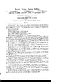
- Figure 1 is a front elevation.
- v Figure 2 isa-planview.
- Figure 3 is a detached section of the driving-pulleys- Figure 4 is a detached section of the chiselfholder.
- the nature of this invention relates to the construction and arrangement of'a mortising-machine, for mortisingsash-stiles lin a more expeditious and perfect manner than is now done by the ordinary means, and consists in the manner of arranging the guides or rests and bed upon which the stiles are placed, their adjust- ⁇ ability, and the perfection of the work done; also, in the manner ofl attaching and arranging the chisel-holders upon thecrosshead, so that they shall perfectly retain their perpendicular position and still bereadily shifted upon the same, to accommodate'them to'diiferent widths of Stiles.
- the driving-pulleys at the top of the machine are placed in a sliding box, which is operated by the foottreadle, to bring the crosshead down to the worli.
- the bearings or ⁇ slides for the play of the cross-head are so constructed that,whenever they becomeworn they may be tightened, and so kept in good working order.
- the projections or ways o. a for supporting the sliding bedv B, gs. 1 and 2.
- This bed is provided, at each end, with a V shaped groove, a', which rests upon a corresponding-V-shaped tongue upon the Ways a a.
- the guide-restsc c which are constructed with slots, through which the thumb sst-screws c"c pass into the bed B, for the purpose of securing the guides in a position suitable to the different sizes of stilles.
- the guide-rests c o have'upon their innei ⁇ ends a stop, d, arranged with set-screws d', to adjust them to the .various thickness of stiles, which serve to hold the stiles down in place while the machine is in operation.
- a. projection or arm, D seen in detachcd'sections, lig. 5, to which is :attached a hand-wheel, j', which carries the pinion g, said pinion meshing and working with the ratchet h, said 4ratchet being made on the under 'side of arm D', projecting from and secured to the frame A.
- 'E is a cross-head, having a slot, E,Ain which are arranged the chisel-holders F F, seen also 1n iig. 4.
- n In the under side of the cross-head is cut a groove, n, the chisel-holder having a corresponding tongue, n', which fits the said groove. l
- the chisel-holders also have a projection, O, which lits the slot E.
- A'screw,p having.a"head and shoulders,'p, which also fits the slot E', passes through the chisel-holder F, and a thumb-nut, q, secures the same firmly in place.
- the Shanks ofthe chisels are slightly tapering, and fit into corresponding sockets in the chisel-holders.
- the object of this molle of constructing and arranging the chisel-holders is to insure their permanency in-an upright position, and yet they may be easily and readily shifted as Voccasion may require.
- the ⁇ bearings t and t of the slides of the'cross-head are triangular or V-shaped, so that whenever they 'become worn they 4may be tightened by setting up the screws u win the same.
- the driving-pulley is located on the top of the standnrd A.l There is a wheel, r, upon the same shaft, and
- a lever, L is hung in the frame A, having a.- weight, m, uttztched to'the long arm, the short arm being attached, by ald'ouble joint, to the-pulley-boxes.
- the said weight m over- Ybalancing them, keeps the pulleys and cross-head up.
- Thechisels are bevel-sided, to suit the different-shaped motises, as they are to be made in the 'sash-stile's, the centre chisel being made to cut the ⁇ inner mortise of the stiles.
- adjustable stops b Attached to the ways a a of the frame A, and opposite to the ends of the bed B, are adjustable stops b which serve as guides for placing the cross-bars when they are to be mortised.
- the chisel-holders F F constructed as described,' in combination with the cross-head E, to operate as and for the purpose. set forth. v
Landscapes
- Life Sciences & Earth Sciences (AREA)
- Engineering & Computer Science (AREA)
- Wood Science & Technology (AREA)
- Mechanical Engineering (AREA)
- Forests & Forestry (AREA)
- Dovetailed Work, And Nailing Machines And Stapling Machines For Wood (AREA)
Description
JAMES M. JOHNSON AND JOHN HERIG, OF CLEVELAND, OHIO.
Lettere Patent No. 82,004,-d ated September 8, 1868.
IMPROVEMENT IN MORTISING-MAGHINES.
dit .rlgnmle ritmi tu in tigen Enters moet mit mating part nf the same.
TO ALL WHOM IT MAY CONOERN:
Be it known that we, JAMES M. JoHNsoN and Jenn Henle, of Cleveland, county of Cuyahoga, in the State of Ohio, have invented a new and improved Sash-Mortising Machine;` and we do hereby declare that the following is a full and exact description thereof, reference Abeing had to the accompanying drawings, and to the letters of reference marked thereon. i
Figure 1 is a front elevation.
vFigure 2 isa-planview.
Figure 3 is a detached section of the driving-pulleys- Figure 4 is a detached section of the chiselfholder.
Figure 5,section of the ratchet and pinion for moving the bed Figure 6, section of cross-head, showing the bearings.
Figure 7, 'section showing the connectionbetween the treadle and sliding-pulley box.
The nature of this invention relates to the construction and arrangement of'a mortising-machine, for mortisingsash-stiles lin a more expeditious and perfect manner than is now done by the ordinary means, and consists in the manner of arranging the guides or rests and bed upon which the stiles are placed, their adjust- `ability, and the perfection of the work done; also, in the manner ofl attaching and arranging the chisel-holders upon thecrosshead, so that they shall perfectly retain their perpendicular position and still bereadily shifted upon the same, to accommodate'them to'diiferent widths of Stiles. I
The driving-pulleys at the top of the machine are placed in a sliding box, which is operated by the foottreadle, to bring the crosshead down to the worli.
The bearings or `slides for the play of the cross-head are so constructed that,whenever they becomeworn they may be tightened, and so kept in good working order.
Upon theframe and standard A, which may be of cast iron,I of suitable strength and proportions, is
'arranged the machinery comprising our improvements.
On the front and near the sides of the frame A are cast the projections or ways o. a, for supporting the sliding bedv B, gs. 1 and 2. This bed is provided, at each end, with a V shaped groove, a', which rests upon a corresponding-V-shaped tongue upon the Ways a a.
Upon the top of said bed B are arranged the guide-restsc c, which are constructed with slots, through which the thumb sst-screws c"c pass into the bed B, for the purpose of securing the guides in a position suitable to the different sizes of stilles.
The guide-rests c o have'upon their innei` ends a stop, d, arranged with set-screws d', to adjust them to the .various thickness of stiles, which serve to hold the stiles down in place while the machine is in operation.
There are also springs e e placed upon said bed B, to hold the stiles up against the guides c c.
,In front of the bed B is arranged a. projection or arm, D, seen in detachcd'sections, lig. 5, to which is :attached a hand-wheel, j', which carries the pinion g, said pinion meshing and working with the ratchet h, said 4ratchet being made on the under 'side of arm D', projecting from and secured to the frame A.
Upon the top of said arm D is placed a slotted strip, t', secured by a set-screw, k. Upon4 the side of said arm D is'a similar strip, t", and set-screw k. These, which may set as desired, are intended to determine the length of the mortise.
'E is a cross-head, having a slot, E,Ain which are arranged the chisel-holders F F, seen also 1n iig. 4.
In the under side of the cross-head is cut a groove, n, the chisel-holder having a corresponding tongue, n', which fits the said groove.. lThe chisel-holders also have a projection, O, which lits the slot E.
A'screw,p, having.a"head and shoulders,'p, which also fits the slot E', passes through the chisel-holder F, and a thumb-nut, q, secures the same firmly in place.
The Shanks ofthe chisels are slightly tapering, and fit into corresponding sockets in the chisel-holders. The object of this molle of constructing and arranging the chisel-holders is to insure their permanency in-an upright position, and yet they may be easily and readily shifted as Voccasion may require.
The `bearings t and t of the slides of the'cross-head are triangular or V-shaped, so that whenever they 'become worn they 4may be tightened by setting up the screws u win the same.
The driving-pulley is located on the top of the standnrd A.l There is a wheel, r, upon the same shaft, and
is connected with the cross-head by the connecting-rod r. The journals of this shaft are seated i n the sliding bores said boxes beingI enclosed in the `framework y y, and are connected by the rod z to the foot-treadle z', by which means the cross-head is made to approach the work.
To keep-the cross-head up from the work a lever, L, is hung in the frame A, having a.- weight, m, uttztched to'the long arm, the short arm being attached, by ald'ouble joint, to the-pulley-boxes. The said weight m, over- Ybalancing them, keeps the pulleys and cross-head up. Y Y
Thechisels are bevel-sided, to suit the different-shaped motises, as they are to be made in the 'sash-stile's, the centre chisel being made to cut the`inner mortise of the stiles.
When this is to be done, the guide-rests c c are to be moved back, as seen in dotted'v line, iig. 2, and a small strip, B', placed upon thebed B, and having bevelled groove cut into it to fit and hold the bevelled cross-bars of a window-sash. I
Attached to the ways a a of the frame A, and opposite to the ends of the bed B, are adjustable stops b which serve as guides for placing the cross-bars when they are to be mortised. i
What we claim as our improvement, and desire to'secure by Letters Patent, is
The chisel-holders F F, constructed as described,' in combination with the cross-head E, to operate as and for the purpose. set forth. v
JAMES M. JOHNSON, JOHN HERIG.
Witnesses: u
GEO. BESTER, GEO. W. TIBBITTS.
Publications (1)
| Publication Number | Publication Date |
|---|---|
| US82004A true US82004A (en) | 1868-09-08 |
Family
ID=2151497
Family Applications (1)
| Application Number | Title | Priority Date | Filing Date |
|---|---|---|---|
| US82004D Expired - Lifetime US82004A (en) | Improvement in mortising-maohines |
Country Status (1)
| Country | Link |
|---|---|
| US (1) | US82004A (en) |
Cited By (2)
| Publication number | Priority date | Publication date | Assignee | Title |
|---|---|---|---|---|
| US20120151599A1 (en) * | 2010-12-09 | 2012-06-14 | SolaByte New Media Services LLC | Electronic system for the protection and control of license transactions associated with the disablement of replicated read only media and its bound licensed content |
| US20140219251A1 (en) * | 2011-10-19 | 2014-08-07 | Panasonic Corporation | Communication terminal and encoding rate reduction method |
-
0
- US US82004D patent/US82004A/en not_active Expired - Lifetime
Cited By (2)
| Publication number | Priority date | Publication date | Assignee | Title |
|---|---|---|---|---|
| US20120151599A1 (en) * | 2010-12-09 | 2012-06-14 | SolaByte New Media Services LLC | Electronic system for the protection and control of license transactions associated with the disablement of replicated read only media and its bound licensed content |
| US20140219251A1 (en) * | 2011-10-19 | 2014-08-07 | Panasonic Corporation | Communication terminal and encoding rate reduction method |
Similar Documents
| Publication | Publication Date | Title |
|---|---|---|
| US82004A (en) | Improvement in mortising-maohines | |
| US1993A (en) | Manufacture of plows | |
| US94227A (en) | Improved pastry-roller | |
| US101788A (en) | Improvement in scroll-sawing machines | |
| US86293A (en) | Improvement in mortising-machines | |
| US64779A (en) | Improvement in machines foe making dooe and window-peames | |
| US96224A (en) | Improvement in method of adjusting circular saws | |
| US183931A (en) | Improvement in saw-sharpeners | |
| US787519A (en) | Saw-set. | |
| US396298A (en) | Wood-working machine | |
| US95391A (en) | Improvement in apparatus tor sharpening- and gumming xaws | |
| US392943A (en) | blake | |
| US125215A (en) | Improvement in sawing-machines | |
| US199285A (en) | Improvement in mortising and boring machines | |
| US147039A (en) | Improvement in saw-gumming machines | |
| US96078A (en) | Improvement in machine for sharpening saws | |
| US72951A (en) | Improvement in machine poe geinding and polishing articles of metal | |
| US615313A (en) | Milling-machine | |
| US386806A (en) | Circular sawing machine | |
| US109060A (en) | Improvement in scroll-saws | |
| US82600A (en) | Improvement in turning wagon-hubs | |
| US59841A (en) | Samuel jackson | |
| US114183A (en) | Improvement in machines for boring and mortising | |
| US24688A (en) | Machine fob boring ob mortising blind-stiles | |
| US53120A (en) | Improved saw-grinding machine |