US8185257B2 - Automated system with deterministic response times - Google Patents
Automated system with deterministic response times Download PDFInfo
- Publication number
- US8185257B2 US8185257B2 US12/446,724 US44672408A US8185257B2 US 8185257 B2 US8185257 B2 US 8185257B2 US 44672408 A US44672408 A US 44672408A US 8185257 B2 US8185257 B2 US 8185257B2
- Authority
- US
- United States
- Prior art keywords
- subsystem
- processing
- instruction
- timer
- duration
- Prior art date
- Legal status (The legal status is an assumption and is not a legal conclusion. Google has not performed a legal analysis and makes no representation as to the accuracy of the status listed.)
- Expired - Fee Related, expires
Links
Images


Classifications
-
- G—PHYSICS
- G06—COMPUTING; CALCULATING OR COUNTING
- G06F—ELECTRIC DIGITAL DATA PROCESSING
- G06F9/00—Arrangements for program control, e.g. control units
- G06F9/06—Arrangements for program control, e.g. control units using stored programs, i.e. using an internal store of processing equipment to receive or retain programs
- G06F9/46—Multiprogramming arrangements
- G06F9/48—Program initiating; Program switching, e.g. by interrupt
- G06F9/4806—Task transfer initiation or dispatching
- G06F9/4843—Task transfer initiation or dispatching by program, e.g. task dispatcher, supervisor, operating system
- G06F9/4881—Scheduling strategies for dispatcher, e.g. round robin, multi-level priority queues
- G06F9/4887—Scheduling strategies for dispatcher, e.g. round robin, multi-level priority queues involving deadlines, e.g. rate based, periodic
-
- G—PHYSICS
- G06—COMPUTING; CALCULATING OR COUNTING
- G06F—ELECTRIC DIGITAL DATA PROCESSING
- G06F9/00—Arrangements for program control, e.g. control units
- G06F9/06—Arrangements for program control, e.g. control units using stored programs, i.e. using an internal store of processing equipment to receive or retain programs
- G06F9/46—Multiprogramming arrangements
- G06F9/52—Program synchronisation; Mutual exclusion, e.g. by means of semaphores
-
- G—PHYSICS
- G08—SIGNALLING
- G08G—TRAFFIC CONTROL SYSTEMS
- G08G5/00—Traffic control systems for aircraft, e.g. air-traffic control [ATC]
- G08G5/0017—Arrangements for implementing traffic-related aircraft activities, e.g. arrangements for generating, displaying, acquiring or managing traffic information
- G08G5/0021—Arrangements for implementing traffic-related aircraft activities, e.g. arrangements for generating, displaying, acquiring or managing traffic information located in the aircraft
-
- G—PHYSICS
- G08—SIGNALLING
- G08G—TRAFFIC CONTROL SYSTEMS
- G08G5/00—Traffic control systems for aircraft, e.g. air-traffic control [ATC]
- G08G5/003—Flight plan management
- G08G5/0034—Assembly of a flight plan
Definitions
- the present invention relates to an automated or semi-automated system, in particular a navigation system, with deterministic response times.
- a flight management system comprises various functional components which enable the crew to program a flight from a navigation database.
- the system then calculates a lateral and vertical trajectory making it possible to reach the destination of the flight plan based on the characteristics of the aircraft and the data supplied by the crew and the environment of the system.
- the positioning and guidance functions collaborate to help the pilot remain on this trajectory.
- the interface functions with the crew and with the ground make it possible to include humans in the navigation loop, because they are solely responsible for the progress of the flight.
- FIG. 1 is a block diagram of an FMS. It mainly comprises the following functions: HMI (human-machine interface), “GUIDANCE”, “LOC” (location), “PRINTER” (printers), “PRED” (predictions), “NAVDB” (navigation databases), “DATALINK” (ground-air digital link), “TRAJ” (definition of trajectory), “FPLN” (flight plan), “IO” (inputs and outputs), “DUAL” (redundancy management) and “SPARE”, a function existing in certain FMSs, but with a functionality different than that of the inventive “SPARE” function, and which has therefore been represented outside the FMS proper, and which is described hereinbelow with reference to the invention.
- a flight management system combines a large quantity of data:
- a flight management system is therefore extremely complex, in particular according to the quantity of information that it processes.
- FIG. 2 is a simplified block diagram representation of the various flight plan revision steps.
- the main functions implemented are represented at the top of the figure, but obviously other functions can be implemented. These functions are: a human-machine interface HMI, the flight plan computer FPLN (which is a subset of the FMS computer), the navigation database NavDB, and the trajectory prediction TRAJ/PRED.
- HMI human-machine interface
- FPLN flight plan computer
- NavDB navigation database
- TRAJ/PRED trajectory prediction
- FPLN sends to the prediction system TRAJ/PRED the new flight plan ( 7 ), that is, the flight plan incorporating the modification corresponding to the revision instruction 1 .
- This prediction system calculates its short-term predictions ( 8 ) and communicates the results thereof ( 9 ) to the HMI interface. The latter displays the update ( 10 ).
- the time taken to perform the steps 1 to 10 is the response time of the FMS system in performing a revision of the flight plan.
- the TRAJ/PRED function calculates the long-term path predictions, to the destination of the current flight ( 11 ). Once this calculation is completed, the TRAJ/PRED function sends ( 12 ) the HMI interface the available version of the long-term flight predictions (taking into account the revision concerned). Finally, the HMI interface updates the display of the long-term prediction information ( 13 ). The time taken to perform the steps 10 to 13 is the display update time.
- the four actions 3 , 5 , 8 and 10 identify the variable parts in the family of flight plan revision operations.
- the first ( 3 ) which corresponds to a search in the navigation database, takes a time that is dependent on the type of data sought and the size of the database.
- the second ( 5 ) which corresponds to the actual inclusion of the modification requested by the pilot, depends on the type of modification and the size of the data received from the database.
- the third ( 8 ) which corresponds to the calculation of the reference trajectory and of the short-term speed, altitude, time, fuel, temperature, wind, and other predictions to a distance near to the aircraft (a few points or tens of nautical miles), depends on the geometry of the flight plan and on the context of the aircraft.
- the fourth ( 10 ) which corresponds to the update of the information displayed on the operator screens, depends mainly on the information that the operator has chosen to display and the size of the flight plan.
- the two steps 11 and 13 identify the variable parts of the updating of the trajectory and of the predictions.
- the first ( 11 ) which corresponds to the calculation of the reference trajectory and of the predictions to the destination of the flight plan, depends on the distance to be covered and the number of procedural operations to be performed to the destination.
- the present invention relates to an automated system, in particular a system handling vital functions, such as an FMS, this system comprising several functional subsystems with variable external instruction processing times, this system potentially being subject to changes, and its subject is a device making it possible to determine which, in this system, are the subsystems that prevent it being deterministic, in order to correct the behavior of these subsystems and make this system secure.
- a system handling vital functions such as an FMS
- this system comprising several functional subsystems with variable external instruction processing times, this system potentially being subject to changes, and its subject is a device making it possible to determine which, in this system, are the subsystems that prevent it being deterministic, in order to correct the behavior of these subsystems and make this system secure.
- the automated system according to the invention is a system for which the response time to one and the same command is independent of the volume of internal and external data manipulated and any future functional changes, and it is characterized in that it comprises, in each of its subsystems that have variable processing times and/or are likely to change, an explicit resource consuming subsystem simulating a processing time, the duration of which is at least equal to the difference between the maximum processing duration predictable at the end of life of the subsystem that incorporates it and the current processing duration, and a timer subsystem triggered by a processing instruction for which the timer duration is at least equal to the current processing time of said instruction plus the time determined by the explicit resource consuming subsystem.
- the maximum predictable processing duration and the current processing duration are determined on a measurement bench, each time the subsystems concerned are changed, for example.
- FIG. 1 is a block diagram of a flight management system FMS comprising the inventive device
- FIG. 2 is a timing diagram of the various steps implemented to take into account a flight plan revision instruction
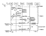
- FIG. 3 is a timing diagram similar to that of FIG. 2 , but with the intervention of the SPARE and TIMER subsystems according to the invention.
- the invention is described hereinbelow with reference to its application to an aircraft navigation system (FMS), but obviously it is not limited to this one application, and it can be implemented in any automated or semi-automated system comprising several functional subsystems with external instruction processing times that are variable and which can be subject to changes.
- FMS aircraft navigation system
- the inventive device comprises, in addition to the FMS, an explicit resource consuming subsystem “SPARE”, this SPARE subsystem being combined with a “TIMER” subsystem.
- SPARE explicit resource consuming subsystem
- TIMER a common service in an onboard system, but its use to control the response times of the FMS is an important characteristic of the invention.
- the SPARE subsystem produced, for example, using a calibrated timer loop, can be parameterized during the development of the FMS system to “consume” the calculation time that can be predicted at the end of life of the system for which it is responsible for determining the external instruction processing time.
- this SPARE subsystem is divided among each of the other subsystems of the FMS that are likely to change, in order that, throughout the life of the FMS, its response time is the same, regardless of these changes. This makes it possible in particular to make the FMS system more deterministic and to make its behavior secure on certification and not only on intermediate deliveries of these subsystems.
- the TIMER subsystem of the inventive device is a timer device determining a “certain” time period (typically of the order of one second), on expiry of which it sends a signal to the SPARE subsystem to enable it to respond to the incoming information, which makes it possible, in normal operating conditions, not to slow down the FMS system by initiating actions that in any case have to be canceled (to avoid the so-called “flicker” effect).
- the SPARE subsystem is called in the context of the subsystem needing to have a deterministic behavior (for example, the navigation database manager mentioned in the example described hereinabove with reference to FIG. 2 ).
- This subsystem is capable of consuming a precise time, according to the context of the platform.
- the degree of precision is of the order of one cycle of the system (a typical response time to an action on the part of the pilot is of the order of one second, whereas the cycle time is of the order of 50 ms).
- the SPARE subsystem globally represents the upgrade capabilities of the various subsystems that are synchronous to a greater degree of precision, because they consume a time far less than the time of a cycle. This precision is of the order of 1% of a cycle.
- the TIMER subsystem is, initially, launched on calling a relatively short processing sequence, for example of the order of a few hundreds of milliseconds (like that described hereinabove with reference to FIG. 2 ). If the time period that it measures is not consumed at the end of the processing, the result of this sequence is not provided until the duration has elapsed. During this time, longer processing operations are launched, for example lasting several seconds. If these long processing operations are completed at the moment identified as the end of the sequence, the display of the result of this short sequence will be more complete, otherwise the intermediate results are presented, but the pilot has a deterministic response time.
- the TIMER service does not eliminate all the possible flickers (the response time expected by the pilot being less than the time needed for the complete calculation), it eliminates them in the most critical phase of a commercial flight: the approach phase.
- the inventive solution proposes harmonizing the response times of the FMS system between the various scenarios of one and the same family, as and when changes are made to the product and its usage context.
- the operator in this case the pilot thus has a system that responds in a completely deterministic way, both in the simplest operation implementing a navigation database and in more complex operations of subsequent versions, for example with a database having doubled in size.
- the product development team does not have to monitor all the possible cases to control the performance characteristics of the product, because all it needs to do is to record the response time overruns of the various subsystems of the FMS, each taken separately (in the case where the timing out of the TIMER occurs before the end of the processing), and remedy them as appropriate.
- the database NavDB After this time period, the database NavDB performs a search in its data ( 23 ), then its SPARE subsystem counts down another time period SPARE- 2 (intended to take account of the predictable change in the size of the database) and sends the result ( 24 ) to FPLN which performs a linkage of the flight plan ( 25 ) to incorporate the data that NavDB has just sent it in the current flight plan.
- the time periods SPARE- 2 and SPARE- 3 can be combined into a single time period, taking place before or after the search step 23 .
- the SPARE subfunction of FPLN then counts down a time period SPARE- 3 intended to take account of the response times between different types of revisions.
- FPLN sends a corresponding “status OK” indication ( 26 ) to the HMI interface to display this status to the pilot. Also FPLN sends the prediction system TRAJ/PRED the new flight plan ( 27 ), that is, the flight plan incorporating the modification corresponding to the revision instruction 21 B.
- the SPARE subsystem incorporated in the prediction system counts down a time period SPARE- 4 , then TRAJ/PRED performs a calculation of short-term predictions ( 28 ) and signals ( 29 ) to HMI that it has a new draft flight plan updated in the short term.
- the HMI interface waits for a time period TIMER- 1 to elapse taking account of the elapsing of all the time periods of the various SPARE subsystems (only the time periods relating to the FPLN, NavDB and TRAJ/PRED subsystems are mentioned in FIG. 3 ).
- the TIMER subsystem signals ( 30 ) to HMI that it can release the display of the short-term predictions (sent to it in 29 ). HMI therefore then displays these short-term predictions ( 31 ).
- the time period between the transmittal of the instruction 21 / 21 A and the display 31 is of the order of one second.
- the SPARE subsystem of the TRAJ/PRED subsystem initiates another timer SPARE- 5 before beginning the long-term prediction calculations ( 32 ).
- the display release instruction 30 is sent after the start of the calculation 32 , but it can equally be sent before this start.
- the HMI computer after having begun the display of the short-term predictions, sends an instruction ( 33 ) to the TIMER for it to begin counting down a time period TIMER- 2 (of approximately three seconds, for example), intended to eliminate the abovementioned flicker effect. While this time period is being counted down, at the end of the calculation 32 , the TRAJ/PRED subsystem sends HMI ( 34 ) the long-term version of the prediction calculations.
- the TIMER subsystem sends a signal ( 35 ) to the HMI interface, enabling it to display the long-term predictions, which are then effectively displayed ( 36 ).
Landscapes
- Engineering & Computer Science (AREA)
- Physics & Mathematics (AREA)
- General Physics & Mathematics (AREA)
- Software Systems (AREA)
- Theoretical Computer Science (AREA)
- Aviation & Aerospace Engineering (AREA)
- General Engineering & Computer Science (AREA)
- Traffic Control Systems (AREA)
- Navigation (AREA)
Applications Claiming Priority (4)
| Application Number | Priority Date | Filing Date | Title |
|---|---|---|---|
| FR0703386A FR2916067B1 (fr) | 2007-05-11 | 2007-05-11 | Systeme automatise aux temps de reponse deterministes |
| FR0703386 | 2007-05-11 | ||
| FR07/03386 | 2007-05-11 | ||
| PCT/EP2008/055740 WO2008141953A1 (fr) | 2007-05-11 | 2008-05-09 | Systeme automatise aux temps de reponse deterministes |
Publications (2)
| Publication Number | Publication Date |
|---|---|
| US20100087969A1 US20100087969A1 (en) | 2010-04-08 |
| US8185257B2 true US8185257B2 (en) | 2012-05-22 |
Family
ID=38787559
Family Applications (1)
| Application Number | Title | Priority Date | Filing Date |
|---|---|---|---|
| US12/446,724 Expired - Fee Related US8185257B2 (en) | 2007-05-11 | 2008-05-09 | Automated system with deterministic response times |
Country Status (3)
| Country | Link |
|---|---|
| US (1) | US8185257B2 (fr) |
| FR (1) | FR2916067B1 (fr) |
| WO (1) | WO2008141953A1 (fr) |
Families Citing this family (4)
| Publication number | Priority date | Publication date | Assignee | Title |
|---|---|---|---|---|
| FR2938939B1 (fr) | 2008-11-25 | 2015-10-02 | Thales Sa | Procede d'aide a la gestion du vol d'un aeronef en vue de tenir une contrainte de temps |
| FR2954847B1 (fr) * | 2009-12-30 | 2012-10-26 | Thales Sa | Systeme et procede de gestion centralisee d'informations de navigation |
| DE102011050880A1 (de) * | 2011-06-07 | 2012-12-13 | Amazonen-Werke H. Dreyer Gmbh & Co.Kg | HMI eines landwirtschaftlichen Gerätes |
| FR3003971B1 (fr) * | 2013-03-28 | 2017-02-17 | Airbus Operations Sas | Procede et dispositif de calcul de predictions sur un plan de vol d'un aeronef. |
Citations (6)
| Publication number | Priority date | Publication date | Assignee | Title |
|---|---|---|---|---|
| EP0798685A1 (fr) | 1996-03-29 | 1997-10-01 | The Boeing Company | Méthode et appareil pour un système de gestion de vol procurant la liaison d'un ségment de route saillant à partir d'une position prédéterminée d'un plan de vol existant |
| US6122572A (en) * | 1995-05-08 | 2000-09-19 | State Of Israel | Autonomous command and control unit for mobile platform |
| US20040078136A1 (en) * | 2002-10-22 | 2004-04-22 | Cornell Bradley D. | Tailored trajectory generation system and method |
| US6922703B1 (en) | 1999-09-14 | 2005-07-26 | Honeywell International Inc. | Methods and apparatus for real-time projection and rendering of geospatially organized data |
| US20060036879A1 (en) * | 2004-08-16 | 2006-02-16 | Standard Microsystems Corporation | Failsafe slave mechanism for mission critical applications |
| US20080168285A1 (en) * | 2007-01-07 | 2008-07-10 | De Cesare Joshua | Methods and Systems for Power Management in a Data Processing System |
-
2007
- 2007-05-11 FR FR0703386A patent/FR2916067B1/fr not_active Expired - Fee Related
-
2008
- 2008-05-09 US US12/446,724 patent/US8185257B2/en not_active Expired - Fee Related
- 2008-05-09 WO PCT/EP2008/055740 patent/WO2008141953A1/fr active Application Filing
Patent Citations (6)
| Publication number | Priority date | Publication date | Assignee | Title |
|---|---|---|---|---|
| US6122572A (en) * | 1995-05-08 | 2000-09-19 | State Of Israel | Autonomous command and control unit for mobile platform |
| EP0798685A1 (fr) | 1996-03-29 | 1997-10-01 | The Boeing Company | Méthode et appareil pour un système de gestion de vol procurant la liaison d'un ségment de route saillant à partir d'une position prédéterminée d'un plan de vol existant |
| US6922703B1 (en) | 1999-09-14 | 2005-07-26 | Honeywell International Inc. | Methods and apparatus for real-time projection and rendering of geospatially organized data |
| US20040078136A1 (en) * | 2002-10-22 | 2004-04-22 | Cornell Bradley D. | Tailored trajectory generation system and method |
| US20060036879A1 (en) * | 2004-08-16 | 2006-02-16 | Standard Microsystems Corporation | Failsafe slave mechanism for mission critical applications |
| US20080168285A1 (en) * | 2007-01-07 | 2008-07-10 | De Cesare Joshua | Methods and Systems for Power Management in a Data Processing System |
Non-Patent Citations (3)
| Title |
|---|
| Charlie McElhone, "Soft Computations within Integrated a Vionics System", Proceedings of the IEEE 2000 National Aerospace and Electronics Conference (NAECON 2000), Oct. 10, 2000, pp. 27-34, IEEE, Piscataway, N.J., USA. |
| John Penix, et al., "Verifying Time Partitioning in the DEOS Scheduling Kernel", Formal Methods in System Design, Mar. 1, 2005, pp. 103-135, vol. 26, No. 2, Kluwer Academic Publishers. |
| Pam Binns, "A Robust High-Performance Time Partitioning Algorithm: The Digital Engine Operating System (DEOS) Approach", Proceedings 20th Digital Avionics Systems Conference (DASC), Oct. 14, 2001, pp. 1.B.6-1-1.B.6-12, vol. 1, IEEE, Piscataway, N.J., USA. |
Also Published As
| Publication number | Publication date |
|---|---|
| US20100087969A1 (en) | 2010-04-08 |
| WO2008141953A1 (fr) | 2008-11-27 |
| FR2916067A1 (fr) | 2008-11-14 |
| FR2916067B1 (fr) | 2009-08-21 |
Similar Documents
| Publication | Publication Date | Title |
|---|---|---|
| US6317659B1 (en) | Layered subsystem architecture for a flight management system | |
| US8832649B2 (en) | Systems and methods for augmenting the functionality of a monitoring node without recompiling | |
| US9972142B2 (en) | Methods, systems and apparatus for automated generation of a flight log and a squawk list file | |
| US20140359564A1 (en) | System for Scheduling Tasks to Control the Execution of Warning Procedures on an Aircraft | |
| US20050028033A1 (en) | Method, apparatus and computer program product for constructing a diagnostic network model | |
| CN110023902B (zh) | 应用开发环境提供系统、方法、终端装置、应用显示方法 | |
| US11036474B2 (en) | Automating service maturity analysis and estimation | |
| EP3396498B1 (fr) | Interface utilisateur prédictive pour système de commande de véhicule | |
| US8185257B2 (en) | Automated system with deterministic response times | |
| US11334829B2 (en) | Methods and systems for electronic checklist data references | |
| CN109478350B (zh) | 确定维护关注的航空器数据记录帧配置的系统和方法 | |
| GB2517174A (en) | Assessment of structural health | |
| US8027757B2 (en) | Method and device for aiding the management of successive flights of an aircraft | |
| US9471407B2 (en) | Parametrizable system for centralized maintenance intended for an aircraft | |
| CN109791481B (zh) | 应用开发环境提供系统、方法、信息处理装置及存储介质 | |
| Tuncali et al. | Experience report: Application of falsification methods on the UxAS system | |
| US20200134940A1 (en) | Aircraft systems and methods for retrospective pilot input analysis | |
| US10429843B1 (en) | Parametrizable automatic piloting system intended for an aircraft | |
| KR101976542B1 (ko) | 항공용 시뮬레이션 모델을 통한 시뮬레이션 제어 방법 및 시스템 | |
| CN116432392A (zh) | 自动驾驶仿真测试方法及测试装置 | |
| KR20130041696A (ko) | 휴대형 항공전자 시스템 개발 장치 및 그 운용 방법 | |
| KR20160043291A (ko) | 항공기 특성과 비행 시험 목적에 최적화한 탑재계측 시스템을 이용한 탑재계측 방법 | |
| US20060149432A1 (en) | Flight Management Architecture and Design Methodology | |
| Karr et al. | An integrated flight-deck decision-support tool in an autonomous flight simulation | |
| Daouk et al. | An approach to human-centered design |
Legal Events
| Date | Code | Title | Description |
|---|---|---|---|
| AS | Assignment |
Owner name: THALES,FRANCE Free format text: ASSIGNMENT OF ASSIGNORS INTEREST;ASSIGNORS:BAUDE, PIERRE;CAILLAUD, CHRISTOPHE;REEL/FRAME:022819/0593 Effective date: 20090609 Owner name: THALES, FRANCE Free format text: ASSIGNMENT OF ASSIGNORS INTEREST;ASSIGNORS:BAUDE, PIERRE;CAILLAUD, CHRISTOPHE;REEL/FRAME:022819/0593 Effective date: 20090609 |
|
| REMI | Maintenance fee reminder mailed | ||
| LAPS | Lapse for failure to pay maintenance fees | ||
| STCH | Information on status: patent discontinuation |
Free format text: PATENT EXPIRED DUE TO NONPAYMENT OF MAINTENANCE FEES UNDER 37 CFR 1.362 |
|
| FP | Expired due to failure to pay maintenance fee |
Effective date: 20160522 |