US8180176B2 - Image processing device, image processing method, image processing program, recording medium with image processing program recorded therein, and image processing processor - Google Patents
Image processing device, image processing method, image processing program, recording medium with image processing program recorded therein, and image processing processor Download PDFInfo
- Publication number
- US8180176B2 US8180176B2 US12/602,273 US60227308A US8180176B2 US 8180176 B2 US8180176 B2 US 8180176B2 US 60227308 A US60227308 A US 60227308A US 8180176 B2 US8180176 B2 US 8180176B2
- Authority
- US
- United States
- Prior art keywords
- pixel blocks
- image processing
- tilt angle
- captured image
- processing device
- Prior art date
- Legal status (The legal status is an assumption and is not a legal conclusion. Google has not performed a legal analysis and makes no representation as to the accuracy of the status listed.)
- Expired - Fee Related, expires
Links
Images


Classifications
-
- H—ELECTRICITY
- H04—ELECTRIC COMMUNICATION TECHNIQUE
- H04N—PICTORIAL COMMUNICATION, e.g. TELEVISION
- H04N5/00—Details of television systems
- H04N5/222—Studio circuitry; Studio devices; Studio equipment
- H04N5/262—Studio circuits, e.g. for mixing, switching-over, change of character of image, other special effects ; Cameras specially adapted for the electronic generation of special effects
- H04N5/2628—Alteration of picture size, shape, position or orientation, e.g. zooming, rotation, rolling, perspective, translation
-
- G—PHYSICS
- G06—COMPUTING OR CALCULATING; COUNTING
- G06T—IMAGE DATA PROCESSING OR GENERATION, IN GENERAL
- G06T5/00—Image enhancement or restoration
- G06T5/80—Geometric correction
-
- G—PHYSICS
- G06—COMPUTING OR CALCULATING; COUNTING
- G06T—IMAGE DATA PROCESSING OR GENERATION, IN GENERAL
- G06T7/00—Image analysis
- G06T7/40—Analysis of texture
- G06T7/41—Analysis of texture based on statistical description of texture
-
- G—PHYSICS
- G06—COMPUTING OR CALCULATING; COUNTING
- G06T—IMAGE DATA PROCESSING OR GENERATION, IN GENERAL
- G06T7/00—Image analysis
- G06T7/70—Determining position or orientation of objects or cameras
-
- H—ELECTRICITY
- H04—ELECTRIC COMMUNICATION TECHNIQUE
- H04N—PICTORIAL COMMUNICATION, e.g. TELEVISION
- H04N23/00—Cameras or camera modules comprising electronic image sensors; Control thereof
- H04N23/60—Control of cameras or camera modules
-
- G—PHYSICS
- G06—COMPUTING OR CALCULATING; COUNTING
- G06T—IMAGE DATA PROCESSING OR GENERATION, IN GENERAL
- G06T2207/00—Indexing scheme for image analysis or image enhancement
- G06T2207/20—Special algorithmic details
- G06T2207/20021—Dividing image into blocks, subimages or windows
Definitions
- the present invention relates to a technique for correcting an image captured by a wearable terminal.
- the wearable terminal is a terminal device that can be used while being worn by a user at all times.
- the wearable terminal has a camera and a microphone, and is capable of keeping the record at all times without an operation by the user.
- a patent document 1 discloses a wearable terminal that supports the memory and memory recall of the user by defining importance levels of information pieces acquired from the camera and the microphone for each event, and capturing these information pieces according to the importance levels.
- the wearable terminal keeps on capturing images while being worn by the user at all times, the qualities of the captured images notably deteriorate because of a motion of the user.
- the captured images are tilted.
- a Patent document 2 discloses a method of correcting a tilt of a captured image by detecting line segments that exist in an upper part of the captured image, and estimating a tilt angle of the captured image as a whole based on tilt angles of the line segments.
- the image correction method disclosed in the Patent document 2 it is presumed that the image is captured with the user standing substantially straight. Therefore, when the image is captured with the user standing substantially straight, it is expected that it is difficult to estimate a horizontal direction based on line segments that exist in a lower part of the captured image due to an influence by a ground and a shadow, while it is easy to estimate the horizontal direction based on line segments of structural objects and the like that exist in the upper part of the captured image.
- the method disclosed in the Patent document 2 has a feature of correcting the captured image by actively making use of the above-stated features of the captured image.
- the expected correction effect is not necessarily obtained when the image correction method disclosed in the Patent document 2 is applied to images captured by the wearable terminal. Since the wearable terminal captures images while being worn by the user at all times, the images captured by the wearable terminal do not always have such simple structures that the captured images can be analyzed after being divided into only upper parts and lower parts. Therefore, the expected correction effect cannot be fully obtained with the method disclosed in the Patent document 2. Furthermore, in the method disclosed in the Patent document 2, a case is not expected where a sufficient feature for detecting tilts of the captured images cannot be obtained. Even in that case, the image correction is automatically performed with use of the estimated tilt angles. Therefore, the captured images may be more tilted in a wrong direction in some cases.
- the above-stated problems lead to a problem of how to select a part of the captured image that is suitable for detecting the tilt. That is, in the case of estimating the tilt of the captured image based on the tilts of the line segments that exist in the captured image, the problem is how to distinguish between an area in which most of the line segments are oriented in the same direction and an area in which the line segments are randomly oriented.
- the captured image is simply divided into the upper part and the lower part based on experiences. Therefore, an application range of this method is limited.
- the present invention provides an image processing device that corrects the tilts of any captured images, especially captured images that are not captured in an upright state such as images captured by the wearable terminal, by analyzing the captured images to estimate tilt angles thereof.
- the areas composing each of the captured images correspond to pixel blocks each composed of pixels that compose a part of the corresponding captured image.
- an image processing device for correcting a captured image composed of pixel blocks each composed of a predetermined number of horizontal and vertical pixels, with use of luminances each relating to a corresponding one of the pixels
- the image processing device comprising: a judgment unit operable to, for each of the pixel blocks, (i) perform calculation by substituting pairs of values in an equation for obtaining a direction distribution, each of the pairs being composed of a value indicating a position of each of pixels that compose the pixel block, and a value indicating one of the luminances that is associated with the position, and (ii) judge whether or not the pixel block is suitable for estimating a tilt angle of a part of the captured image that corresponds to the pixel block based on the obtained directional distribution, the directional distribution showing a distribution of directions each characterized by a part or all of an edge of an object included in the part of the captured image, the part or all of the edge corresponding to linearly-arranged
- the image processing device having the above-stated structure: divides an input image into areas; determines what kind of directional characteristic a texture (luminance change) that exists in each divided area has; selects, based on the judgment, one or more areas in each of which the texture has a unidirectional characteristic; and estimates a tilt angle of the captured image based on the selected areas.
- the texture is a pattern formed as a group of pixels having a large edge strength in the captured image.
- the texture that exists in an area has a unidirectional characteristic when most of the line segments included in the area that have each been formed by connecting adjacent pixels having large edge strengths are oriented substantially in one direction.
- the texture is obtained by performing calculation with use of pairs of positions and luminances each relating to a corresponding one of the pixels included the captured image.
- the edge of the structural objects such as a building is considered to be included in the area.
- the edge of the structural object is highly likely to be oriented in a horizontal or vertical direction. In such a way, the image processing device estimates the tilt angle of the captured image by analyzing pixel information pieces such as luminances in the areas.
- one or more divided areas are areas in each of which most of the line segments are oriented in the same direction, it is possible to estimate the tilt angle of the captured image based on such areas even if these areas do not exist in the upper part of the captured image.
- the image processing device selects only one or more areas in each of which most of the line segments are oriented in the same direction in the captured image regardless of whether or not these areas exist in the upper part of the captured image, and excludes, in advance, one or more areas in each of which the line segments are randomly oriented.
- the image processing device is capable of correctly estimating the tilt angle of the captured image, and correcting the tilt of the captured image even if areas that are suitable for estimating the tilt angle of the captured image and areas that are not suitable for estimating the tilt angle of the captured image exist together in the captured image.
- the judgment unit may calculate directional distributions of luminance gradients.
- the image processing device is capable of recognizing line segments included in the captured image and the directions in which the line segments are oriented as the luminance change and directions in which the luminance changes (i.e. luminance gradients), respectively, the image processing device is capable of determining what proportion of the line segments is oriented in the same direction based on the directional distribution of the luminance gradients.
- the judgment unit may calculate a directional distribution of intensities of luminance spectrums.
- luminance spectrums reflect frequency characteristics of the luminance distributions of the original image, it is possible to obtain a distribution of line segments in the original image by analyzing the luminance spectrums.
- the selection unit may exclude, from selection targets, one or more areas in each of which a ratio of the number of pixels whose luminance change is larger than a predetermined luminance change to the number of all pixels is larger than a predetermined threshold value.
- the judgment unit may judge that an area is suitable for estimating a tilt angle of the area when a variance of the directional distribution of the luminance gradients that has been obtained for the area is smaller than a predetermined value.
- the variance of the directional distribution of the luminance gradients reflects how random line segments included in the area are oriented, it is possible to select an area in which most of the line segments are oriented in the same direction by determining that an area having the small variance is an area suitable for estimating the tilt angle of the area.
- a ratio of the number of pixels whose luminance gradients fall in a predetermined angular range to the number of all pixels may be larger than a predetermined value.
- the predetermined angular range is centered on a mode of the luminance gradients of all the pixels.
- the image processing device may continuously detect tilt angles of a plurality of captured images, and the predetermined angular range may be determined based on tilt angles of one or more of the captured images that have been previously obtained by the correction unit.
- the tilt angles of the captured images may be roughly guessed based on the tilt angles previously obtained by the correction unit.
- the angle range is determined based on the guessed tilt angle of the captured image.
- the predetermined angular range may be determined based on a tilt angle of one of the captured images that has been immediately previously obtained by the correction unit.
- the accuracy of estimating the tilt angle may be incremented by determining the angle range based on the immediately previously adopted tilt angle.
- the judgment unit may judge that an area is suitable for estimating the tilt angle of the area when a variance of the directional distribution of the intensities of the luminance spectrums that has been obtained for the area is smaller than a predetermined value.
- an area in which a variance of a directional distribution of the intensities of the luminance spectrums is small corresponds to an area included in the original image in which how random the line segments are oriented is small. Therefore, it is possible to select an area suitable for estimating the tilt angle.
- the estimation unit may detect line segments included in all of the areas that are selected by the selection unit, and the tilt angle of the captured image may be a mode of tilt angles of the detected line segments.
- the estimation unit detects line segments from all of the selected areas, and estimates the tilt angle of the captured image, it is possible to complete the estimation of the tilt angle of the captured image by performing each of the line segment detection and the tilt estimation only once.
- the estimation unit may detect line segments included in each of the selected areas. Also, a tilt angle of each of the selected areas may be a mode of tilt angles of the detected line segments included in the corresponding area, and the tilt angle of the captured image may be determined based on the tilt angles of the respective selected areas.
- an accuracy of estimation may be increased by performing the line segment detection and the tilt angle estimation individually for each selected area, and further performing estimation of the tilt angle of the captured image based on the tilt angles of the areas.
- the tilt angle of the captured image may be the mode of the tilt angles of the areas.
- one of the modes that is preferentially adopted as the tilt angle of the captured image may have longest line segments that tilt at a tilt angle of one of the selected areas.
- the image processing device may continuously correct tilts of a plurality of captured images, and when a plurality of modes of the tilt angles of the respective selected areas exist, one of the modes that is preferentially adopted as a tilt angle of each of the captured images may be closest to a tilt angle estimated based on tilt angles of one or more captured images that have been previously obtained by the correction unit.
- the tilt angle estimated based on the tilt angles of estimated based on the tilt angles of the captured images previously detected by the estimation unit may be a tilt angle of the captured image that has been immediately previously obtained by the estimation unit.
- the image processing device may continuously correct tilts of a plurality of captured images, and when a ratio of the number of selected areas to the number of all areas that compose each of the captured images is smaller than a predetermined threshold value, the estimation unit may estimate a tilt angle of each of the captured images based on tilt angles of the captured images that have been previously obtained by the correction unit.
- the tilt angle of the captured image estimated by the estimation unit may be a tilt angle of a captured image that has been immediately previously obtained by the correction unit.
- the image processing device may be included in an imaging apparatus including a sensor that detects a tilt angle with respect to a horizontal plane at the time of capturing an image.
- the correction unit may correct the captured image with use of the tilt angle outputted by the sensor.
- the reliability of a tilt angle estimated based on such a small number of areas is low. Therefore, a tilt angle detected by the sensor at the time of capturing the image is adopted. Thus, it is possible to correct the captured image even when the small number of areas is selected.
- the correction unit may not perform the correction.
- the correction unit does not correct the captured image. Thus, it is possible to prevent deterioration in an image quality caused due to correction with use of a wrong tilt angle.
- the image processing device may continuously correct tilts of a plurality of captured images, and when a ratio of the number of pixels whose luminances are each smaller than a predetermined threshold value to the number of all pixels composing each of the captured images is larger than a predetermined value, the correction unit estimates a tilt angle of each of the captured images based on tilt angles of captured images that have been previously obtained by the correction unit.
- the tilt angle of the captured image may be estimated based on the previously obtained tilt angle. Thus, it is possible to correct the captured image even when the captured image is dark.
- the tilt angle of the captured image may be a tilt angle of a captured image that has been immediately previously obtained by the correction unit.
- the tilt angle of the captured image may be estimated based on the immediately previously obtained angle. Thus, it is possible to correct the captured image even when the captured image is dark.
- the image processing device may be included in an imaging device including a sensor that detects a tilt angle with respect to a horizontal plane at the time of capturing an image, and when a ratio of the number of pixels whose luminances are each smaller than a predetermined value to the number of all pixels composing each of the captured images is larger than a predetermined threshold value, the correction unit may correct the captured image with use of the tilt angle outputted by the sensor.
- the correction unit may not perform the correction.
- the sensor may be an acceleration sensor.
- the sensor may be an angular velocity sensor.
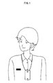
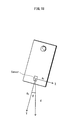
- FIG. 1 shows an example of how a user wears a wearable terminal including an image processing device which is an example of the present invention
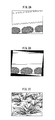
- FIG. 2A , FIGS. 2B and 2C show an example of image correction processing by the image processing device which is an example of the present invention
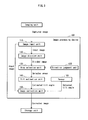
- FIG. 3 shows a structure of the image processing device which is an example of the present invention
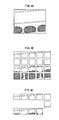
- FIG. 4A , FIG. 4B and FIG. 4C describe an image division and an area selection by the image processing device which is an example of the present invention
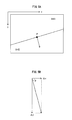
- FIG. 5A and FIG. 5B describe a luminance gradient that exists at a point on a line segment
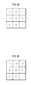
- FIG. 6A and FIG. 6B each show a coefficient matrix used by a Sobel filter
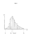
- FIG. 7 shows a luminance gradient histogram generated by the image processing device which is an example of the present invention.
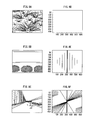
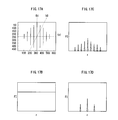
- FIG. 8A , FIG. 8B , FIG. 8C , FIG. 8D , FIG. 8E and FIG. 8F show luminance spectrums corresponding to images
- FIG. 9 shows a flowchart showing an operation of an area selection unit included in the image processing device which is the example of the present invention.
- FIG. 10 shows a flowchart showing processing of generating the luminance gradient histogram of a direction judgment unit included in the image processing device which is the example of the present invention
- FIG. 11A , FIG. 11B and FIG. 11C describe a principle of line segment detection in the Hough transform method
- FIG. 12A and FIG. 12B describe parameters characterizing the line segments in the Hough transform method
- FIG. 13 shows an angle histogram generated by a tilt estimation unit included in the image processing device which is the example of the present invention
- FIG. 14 shows a flowchart showing an operation of the tilt estimation unit included in the image processing device which is an example of the present invention
- FIG. 15 shows a flowchart showing an operation of the line segment detection processing performed by the tilt estimation unit included in the image processing device which is an example of the present invention
- FIG. 16 shows a flowchart showing an operation of an angle histogram generation processing performed by the tilt estimation unit included in the image processing device which is the example of the present invention
- FIG. 17A , FIG. 17B , FIG. 17C and FIG. 17D show cross sections of the luminance spectrums in FIG. FIG. 8A , FIG. 8B , FIG. 8C , FIG. 8D , FIG. 8E and FIG. 8F ;
- FIG. 18 describes a tilt angle detection method with use of a sensor included in the image processing device which is the example of the present invention.
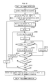
- FIG. 19 is a flowchart showing an operation of the image processing device which is the example of the present invention.
- the present embodiment describes a case where the image processing device that is an example of the present invention is included in a wearable terminal, and corrects a tilt of the image captured by a camera.
- the wearable terminal is a terminal worn by the user (e.g. by dangling it around the neck) at all times, as shown in FIG. 1 .
- the wearable terminal includes a camera, for example, for recording the daily life of the user. Images are captured by the camera without especially needing the operation by the user. Accordingly, images are likely to be captured at timing that is not expected by the user.
- the captured image tilts as shown in FIG. 2A . Since such a tilted image does not look good, the user usually tries to correct the direction in which the object is oriented by tilting the captured image as shown in FIG. 2B .
- the present invention is an image processing device that estimates a right direction by analyzing the captured image to correct the tilt of the captured image without needing the user to correct the tilt of the captured image.
- the image is considered to be tilted when a horizontal direction and a vertical direction of the captured image that can be judged by the object are not parallel to a horizontal direction and a vertical direction respectively that can be determined by a frame of the captured image.
- a horizontal line can be easily estimated based on a pattern of the wall. Since it is detected that the captured image is tilted in an anticlockwise direction a little, it is easy to correct the captured image as shown in FIG. 2B .
- the present invention is highly likely to estimate a right horizontal or vertical direction by analyzing a feature of an area in an image (i.e. whether it is easy or difficult to estimate a horizontal direction as stated in the above).
- FIG. 3 shows the structure of an image processing device which is an example of the present invention.
- An image processing device 100 which is an example of the present invention is composed of an image input unit 110 , an image division unit 120 , a direction judgment unit 125 , an area selection unit 130 , a tilt estimation unit 140 , an image correction unit 150 and a sensor 160 .
- the image processing device 100 which is an example of the present invention is included in the wearable terminal having an imaging unit and a storage unit, corrects a tilt of the captured image captured by the imaging unit, and stores the corrected image in the storage unit.
- the imaging unit is a camera having an imaging device such as a CCD and CMOS sensor, captures an image, and outputs the captured image as an electrical signal.
- an imaging device such as a CCD and CMOS sensor
- the storage unit is a capturing medium such as an SD card or a flush memory, and stores an image outputted by the image processing device 100 which is an example of the present invention.
- the image input unit 110 inputs an image to be corrected by the image processing device 100 .
- the image processing device 100 which is the example of the present invention is not notified of when the captured image to be corrected was captured.
- the image processing device 100 which is the example of the present invention is included in the wearable terminal, and corrects the captured image instantly in the present embodiment
- the image processing device 100 which is the example of the present invention may be prepared separately from an imaging apparatus, and the captured image may be input in the image processing device 100 . It is presumed that an image to be input is an image whose vertical direction and horizontal direction are clearly stipulated, such as a rectangle photograph captured by a normal camera.
- the image division unit 120 divides the input image into a plurality of areas. For example, the image division unit 120 may divide the input image by a ratio by dividing the input image into four equally-spaced areas horizontally and five equally-spaced areas vertically, for example. Alternatively, the image division unit 120 may divide the input image into areas each having a fixed size like a size of 32 horizontal and vertical pixels. For example, the image division unit 120 divides the input image as shown in FIG. 4A into 20 areas as shown in FIG. 4B .
- the tilt estimation unit 140 estimates a tilt of the captured image in view of surface areas of the divided images.
- the direction judgment unit 125 judges whether each of the divided areas is suitable for estimating a tilt angle of the captured image. Whether each of the divided areas is suitable for estimating a tilt angle of the captured image is determined based on what proportion of line segments is oriented in the same direction in the areas. That is, an area in which most line segments are oriented in the same direction is suitable for estimating a tilt angle of the captured image, while an area in which line segments are randomly oriented is not suitable for estimating the tilt angle of the captured image.
- Each of the line segments included in each area of the captured image can be quantitatively detected, as changes in luminances of the pixels, at the micro level. This is because areas are distinguished from one another by a difference in luminance, and a boundary between these areas is detected as a line segment. Accordingly, what proportion of line segments is oriented in the same direction in each area can be determined by judging whether or not directions in which the luminances of the pixels change in each area are random.
- a pattern formed as a group of line segments detected by the difference in luminances of pixels is referred to as a texture.
- the direction judgment unit 125 judges whether or not a texture of each of the divided areas has a unidirectional characteristic.
- the unidirectional characteristic does not mean that all the line segments are oriented completely in the same direction but means that most of the line segments are oriented in almost the same directions between which differences are within a certain range. This range determines an accuracy of estimating the tilt of the captured image.
- a threshold value determined in a design process is used.
- the edge strength may be obtained by pixel information such as a color difference as well as by the luminance.
- the following describes the method of determining a direction in which the luminance changes (i.e. the luminance gradient).
- FIG. 5A and FIG. 5B describe luminance gradient of a point on the line segment.
- I 1 in an area at the upper left
- I 2 in an area at the lower right
- I 1 ⁇ I 2 it is indicated that a boundary between both of the areas is detected as a line segment.
- FIG. 6A and FIG. 6B are coefficient matrixes used for the weighting in the method of using the Sobel filter. A matrix in FIG. 6A is used for performing a calculation for an x element, and a matrix in FIG. 6B is used for performing a calculation for a y element.
- coefficient matrixes are 3-by-3 matrixes, larger matrixes may be used.
- Coefficient matrixes are generally square matrixes of (2k ⁇ 1) ⁇ (2k ⁇ 1) when k is an integer equal to or larger than two.
- the area selection unit 130 calculates luminance gradients of all the pixels included in each area as shown in the above, and judges whether or not the line segments contained in the area are oriented in the same direction. This is performed by generating a luminance gradient histogram that shows a total number of pixels for each value of a luminance gradient as shown in FIG. 7 .
- FIG. 7 is a histogram in which the luminance gradients 8 are shown in a horizontal axis, and P which is the number of pixels having the luminance gradient in a certain range ⁇ is shown in a vertical axis.
- the direction judgment unit 125 generates the luminance gradient histogram as shown in the above.
- the direction judgment unit 125 judges that the texture has a unidirectional characteristic.
- the criterion of this judgment is not limited to the variance of the luminance gradient histogram. Therefore, the direction judgment unit 125 may determine that most of the line segments are oriented in the same direction when the number of pixels whose luminance gradients each have an angle equal to or larger than a predetermined angle is larger than the predetermined threshold value.
- the direction judgment unit 125 determines that the texture of such an area does not have a unidirectional characteristic.
- the methods of determining the directional characteristics of the line segments included in the captured image includes a method that uses a frequency characteristic of the captured image in addition to the method of calculating the luminance gradient for each pixel.
- each of the luminances I(x, y) of pixels that compose the captured image is a discrete function that takes a certain value I(x, y) at discrete two-dimensional coordinates (x, y).
- the direction judgment unit 125 determines a direction based on a luminance spectrum obtained by performing two-dimensional discrete Fourier transform on the luminance I(x, y) of the captured image.
- the luminance spectrum FI(u, v) of the luminance I(x, y) of the captured image is expressed as the following [Equation 7].
- FIG. 8A , FIG. 8B and FIG. 8C are images of weed, a wall and a street, respectively.
- FIG. 8D , FIG. 8E and FIG. 8F can be obtained.
- the luminance spectrums are shifted parallel such that direct current components are in the center of the captured image.
- FIG. 8D shows the luminance spectrum as if it were flat. However, the luminance spectrum looks flat for the convenience of the drawing, and actually has slight rise and fall. It is difficult to estimate a tilt of such an image.
- the luminance spectrums show the strong peaks shown by lines in the vertical direction in FIG. 8E .
- the intensities of the peaks are expressed by the thicknesses of the lines for the convenience of the drawing.
- the line segments in the original image and the peaks shown by the luminance spectrums are mutually orthogonal. Therefore, when the luminance spectrums show strong peaks in the vertical direction, it is estimated that the original image is highly likely to include line segments in the horizontal direction.
- the luminance spectrums show a plurality of peaks in different directions in addition to a strong peak in the vertical direction as shown in FIG. 8F . This is because line segments of the building, a window, a wall and the like that face in various directions exist in the original image.
- the direction judgment unit 125 calculates intensities P( ⁇ ) of luminance spectrums in each direction. That is, when coordinates (u, v) are expressed by polar coordinates (r, ⁇ ), the luminance spectrum intensity P( ⁇ ) in a certain direction ⁇ is expressed by the following [Equation 8] as the sum of squares of the intensities FI(r, ⁇ ) that exist on a line extending in a radial direction.
- the direction judgment unit 125 is capable of determining the directional characteristic based on the information such as a variance of the distribution of the intensities of the luminance spectrums which is expressed as P( ⁇ ) as with the case of using the luminance gradient histogram.
- the area selection unit 130 selects only an area determined to have a unidirectional characteristic by the direction judgment unit 125 from among the areas divided by the image division unit 120 . For example, in an example of FIG. 4C from among the examples shown in FIG. 4A , FIG. 4B and FIG. 4C , the area selection unit 130 selects areas in which horizontal lines of the wall are clearly shown while the area selection unit 130 does not select areas which entirely show a wall and do not have any texture, and areas which are mostly occupied by plants, and do not have textures having unidirectional characteristics.
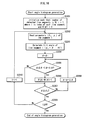
- FIG. 9 is a flowchart showing an operation of the area selection unit 130 that performs area selection based on the directional judgments of the textures by the direction judgment unit 125 .
- the area selection unit 130 instructs the direction judgment unit 125 to generate a luminance gradient histogram of an area i.
- the direction judgment unit 125 receives the instruction from the area selection unit 130 , the direction judgment unit 125 generates the luminance gradient histogram of the area i (Step S 1002 ).
- Step S 1003 If the variance of the luminance gradient histogram generated by the direction judgment unit 125 is smaller than the predetermined threshold value (Step S 1003 : Y), the area selection unit 130 sets the selection flag of the area i (Step S 1004 ), and proceeds to Step S 1005 . If the variance of the luminance gradient histogram generated by the direction judgment unit 125 is equal to or more than the predetermined threshold value (Step S 1003 : N), the area selection unit 130 proceeds to Step S 1005 . If the index i showing the area is equal to or more than N which is the number of divided areas (Step S 1006 : Y), the area selection ends. If the index i showing the area is smaller than N which is the number of divided areas (Step S 1006 : Y), the area selection unit 130 increments i by one (Step S 1007 ), and returns to Step S 1002 .
- FIG. 10 is a flowchart showing how the direction judgment unit 125 performs generation processing of the luminance gradient histogram in the above-stated Step S 1002 .
- the direction judgment unit 125 calculates the luminance gradient ⁇ i in the pixel i (Step S 1102 ).
- the direction judgment unit 125 registers the calculated luminance gradients in the luminance gradient histogram.
- Step S 1108 the direction judgment unit 125 increments ⁇ by ⁇ (Step S 1107 ), and returns to Step S 1104 . This completes the registration of the pixel i in the luminance gradient histogram.
- Step S 1108 If the index i showing the pixel becomes equal to or larger than K which is the number of pixels included in the area (Step S 1108 : Y), the generation processing of the luminous gradient histogram ends. If K which is the number of pixels included in the area is less than K (Step S 1108 : N), the direction judgment unit 125 increments by one (Step S 1109 ), and returns to Step S 1102 . This completes the generation of the luminance gradient histogram.
- the direction judgment unit 125 scans all the pixels included in the area, and then generates the luminance gradient histogram in the above, it is necessary to exclude pixels at end portions of the area from processing targets, for example, when the Sobel filter is used since peripheral pixel information is necessary.
- the luminance gradient histogram P( ⁇ ) indicates a data structure in which the total number of pixels that are within a certain range of ⁇ + ⁇ and ⁇ . Therefore, it is not necessary to actually render a graph on a display and the like.
- the tilt estimation unit 140 estimates, for the area selected by the area selection 130 , a tilt angle of the area based on the pixel information. Firstly, the tilt estimation unit 140 detects line segments included in the area. Next, the tilt estimation unit 140 estimates the tilt angle of the area which is a mode of the tilt angles of the line segments. The tilt estimation unit 140 may estimate the tilt angle by detecting line segments included in all the areas selected by the area selection unit 130 . Alternatively, the tilt estimation unit 140 may separately estimate a tilt angle of each of the areas selected by the area selection unit 130 , and further estimate the tilt angle of the captured image based on the estimated tile angles of the areas.
- the tile angle estimation unit 140 uses the Hough transform method to detect line segments included in each area of the captured image.
- the Hough transform method is a detection method that makes use of a fact that it is highly likely that line segments actually exist in a case where: characteristic points are set at positions in each of the areas of the captured image in each of which line segments are highly likely to exist; and the lines extending from the respective characteristic points are connected supposing that there are straight lines that pass through the characteristic points in various directions with a fixed probability. For example, if it is supposed that straight lines extend from each characteristic point as shown in FIG. 11B in various directions when there are three characteristic points as shown in FIG. 11A , it is highly likely that a straight line exist on the straight line that connects the three characteristic points. Thus, it is assumed that the line segment actually exists.
- the characteristic points are extracted by applying the edge detection filter such as the above-stated Sobel filter on each of the areas of the captured image.
- a point at which two different curves intersect indicates the same straight line that passes through two different characteristics (i.e. a straight line that connects two characteristics).
- three different curves intersect at one point it is indicated that three different characteristic points are on the same straight line.
- a sum of straight lines that are formed by parameters ( ⁇ , ⁇ ), and pass through a characteristic point is obtained for each characteristic point, and a straight line having a figure that exceeds a predetermined threshold value P 0 is detected as a straight line that actually exists.
- the tilt angle estimation unit 140 obtains a sum of tilt angles of the detected line segments included in the respective areas, and estimates an angle having the highest tilt angle as a tilt angle of the area.
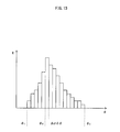
- the tilt angle estimation unit 140 generates, for targeting all the line segments detected in the area, an angle histogram regarding tilt angles, and defines a mode of the tilt angles ⁇ as a tilt angle of the area.
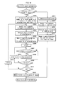
- FIG. 14 is a flowchart showing the operation of the tilt estimation unit 140 .
- the tilt estimation unit 140 performs the above-stated processing on all the areas. If the index i of the area is equal to or larger than N which is the number of selected areas (i ⁇ N) (Step S 2011 : Y), the tilt estimation unit 140 proceeds to Step S 2013 . Finally, the tilt estimation unit 140 selects a mode in the generated histogram Q ( ⁇ ), and defines the mode as an estimation value of the tilt angle of the captured image (Step S 2013 ).
- the tilt angle estimation unit 140 When it is judged that the tilt estimation unit 140 estimates tilt angles of the areas at once in Step S 2001 , the tilt angle estimation unit 140 combines all the areas selected by the area selection unit 130 into one area (Step S 2014 ). The tilt estimation unit 140 detects line segments for the combined area (Step S 2015 ), and generates an angle histogram for the combined area (Step S 2016 ). The tilt estimation unit 140 defines the mode in the angle histogram as an estimation value of a tilt angle of the area (Step S 2017 ).
- FIG. 15 is a flowchart showing the line segment detection in the Hough transform method.
- the tilt estimation unit 140 acquires coordinates (x i , y i ) of the characteristic point i (Step S 2103 ).
- the tilt estimation unit 140 performs initialization such that a parameter ⁇ is ⁇ 1 (Step S 2104 ); and calculates ⁇ i that corresponds to ⁇ (Step S 2105 ).
- the tilt estimation unit 140 performs initialization such that a parameter ⁇ is ⁇ 1 (Step S 2106 ).
- Step S 2107 If ⁇ 1 falls in the range of ⁇ and ⁇ + ⁇ (Step S 2107 : Y), the tilt estimation unit 140 increments P( ⁇ , ⁇ ) by one (Step S 2108 ), and proceeds to Step S 2109 . If ⁇ 1 does not fall in the range of ⁇ and ⁇ + ⁇ (Step S 2107 : N), the tilt estimation unit 140 proceeds to Step S 2109 .
- the tilt estimation unit 140 scans in a ⁇ direction while increasing ⁇ by ⁇ (Step S 2110 ) until ⁇ reaches ⁇ 2 (Step S 2109 : N).
- Step S 2109 the tilt estimation unit 140 scans in a ⁇ direction while increasing ⁇ by ⁇ (Step S 2112 ) until ⁇ reaches ⁇ 2 (Step S 2111 : N).
- Step S 2111 a registration of the characteristic point i in a histogram R( ⁇ , ⁇ ) completes.
- the tilt estimation unit 140 performs the above-stated processing until the index i reaches N which is the number of characteristic points (Step S 2113 : N) while incrementing i by one.
- the tilt estimation unit 140 detects, as a line segment that actually exists, a line segment expressed by ( ⁇ , ⁇ ) whose number of pairs of parameters ⁇ and ⁇ is larger than a threshold value P 0 in the histogram P( ⁇ , ⁇ ).
- FIG. 16 is a flowchart of the angle histogram generation.
- the tilt estimation unit 140 reads, from a memory, parameters ( ⁇ i , ⁇ i ) calculated when detecting a line segment i (Step S 2202 ), and calculates a tilt angle ⁇ i of the line segment i (Step S 2203 ).
- Step S 2206 If the angle ⁇ is equal to or larger than a scanning end angle ⁇ 2 (Step S 2206 : Y), the tilt estimation unit 140 ends the registration of the tilt angle ⁇ i , and proceeds to Step S 2209 . If the angle ⁇ is smaller than a scanning end angle ⁇ 2 (Step S 2206 : N), the tilt estimation unit 140 increments the angle ⁇ by ⁇ (Step S 2208 ), and returns to Step S 2205 .
- the tilt estimation unit 140 performs the above-stated processing on all of the line segments. That is, if the index i is equal to or larger than N which is the number of line segments (Step S 2209 : Y), the tilt estimation unit 140 ends the generation of the angle histogram. When the index i is smaller than N which is the number of line segments (Step S 2209 : N), the tilt estimation unit 140 increments the index i by one (Step S 2210 ), and returns to Step S 2202 .
- the tilt estimation unit 140 estimates that a tilt angle of the area is the mode in the angle histogram. For example, the tilt angle of the area is ⁇ 0 in the case of FIG. 13 .
- the tilt estimation unit 140 estimates the tilt angle of the captured image by detecting line segments from all the areas selected by the area selection unit 130 , the above-mentioned tilt angle of the area is a tilt angle of the captured image.
- the tilt estimation unit 140 estimates the tilt angle of each area as shown in the above, generates a histogram of the tilt angles of the areas and estimates that the tilt angle of the captured image is a mode of the tilt angles of the areas.
- the tilt estimation unit 140 may generate the angle histogram after weighting the angles, depending on tilt angles estimated by a method different from the image analysis. For example, when a plurality of images are captured serially, it is expected that tilt angles also change serially. Therefore, it is possible to improve the accuracy of the estimation by estimating the tilt angle of the captured image based on past tilt angles, adding, to the angle, a weight corresponding to the value, and generating an angle histogram. On the premises that the imaging apparatus is not shaken violently, an immediately preceding tilt angle is considered to be closest to a current tilt angle from among the past tilt angles. When the immediately previously obtained tilt angle is ⁇ prev , a weight w( ⁇ ) as shown in [Equation 10] may be added in accordance with the tilt angles ⁇ .
- a tilt that seems accurate may be estimated by adding weights in accordance with characteristics of the line segments. For example, while a short line segment is likely to be fine patterns drawn on the wall, for example, a long line segment is highly likely to be a part of the structure of the wall such as an edge of the wall. By adding a larger weight to the tilt angle formed by the long line segment than to a tilt angle formed by the short line segment, the tilt estimation unit 140 can detect a horizontal direction or a vertical direction more accurately, and estimate the tilt angle of the captured image correctly.
- the length of each line segment is a distance between two furthest characteristic points from among the characteristic points through which the line segment detected in the Hough transform method passes.
- a weight may be preferentially added to tilt angles formed by line segments that extend in the vertical direction rather than in the horizontal direction. This is because line segments in the captured image are more likely to tilt in the horizontal direction than in the vertical direction due to the perspective. For example, all of the line segments each indicating the horizontal line of the building on the left and right of the captured image as shown in FIG. 8C are actually parallel to the horizontal plane. However, the line segments appear to be radically arranged in the captured image due to the perspective, and tilt in the slightly different directions from one another. The line segments indicating the vertical direction, on the other hand, are always parallel to the vertical direction in the captured image. In view of these facts, it is effective to add weights that depend on the directions in which the line segments are oriented.
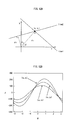
- the tilt estimation unit 140 may estimate the tilt angle with use of the luminance spectrums of the area.
- the cross sections in directions shown by (b), (c) and (d) are shown in 17 B, 17 C and 17 D, respectively. Since a line shown by (b) passes on the peak oriented in the vertical direction in the center of FIG. 17A , a strong signal extends flat without a peak. Since a line shown by (c) is oriented in a direction that crosses the vertical line in FIG. 17A , there are a lot of peaks. Since a line shown by (d) is oriented in the direction between (b) and (c), an interval between peaks are wider than (c).
- the angle histogram may be generated based on the inverse of the number of peaks.
- the tilt estimation unit 140 may estimate the tilt angle based on the directional distribution of the luminance gradients. Specifically, the tilt estimation unit 140 may calculate a directional distribution of the luminance gradients of pixels that belong to each area selected by the area selection unit 130 , and estimate the tilt angle with use of an angle corresponding to a mode of the luminance gradients.
- the sensor 160 detects a direction of a weight of an acceleration sensor or an angular velocity sensor.
- the tilt estimation unit 140 detects the tilt angle of the wearable terminal directly by the sensor 160 .
- Examples of the cases where the tilt estimation unit 140 fails to estimate the tilt angle of the captured image are: a case where the small number of areas are selected by the area selection unit 130 ; and a case where the captured image is dark.
- the tilt estimation unit 140 detects line segments from the selected areas, and estimates the tilt angle of the captured image. Accordingly, in a case where a small number of areas having line segments oriented in the same direction exists in the captured image, the tilt estimation unit 140 cannot estimate the tilt angle of the captured image accurately and as a result the number of selected areas is small. Also, since the tilt estimation unit 140 estimates the tilt angle of the captured image based on the luminance, the tilt estimation unit 140 cannot estimate the tilt angle of the captured image accurately when the captured image as whole is dark. In such a case, the tilt angle detected by the sensor 160 reflects the tilt angle of the captured image more accurately than the tilt angle of the captured image estimated by the tilt estimation unit 140 .
- the sensor 160 uses a biaxial acceleration sensor so as to detect accelerations in two directions that are perpendicular to the image-capturing direction of the camera of the wearable terminal simultaneously with use of a sensor such as a piezoresistive acceleration sensor that converts an applied acceleration into an electrical signal, for example.
- the sensor 160 is fixed on the wearable terminal such that the sensor 160 can detect the acceleration in the x direction and they direction with a y axis and an x axis indicating in the vertical direction and the horizontal direction respectively when the wearable terminal is not tilted.
- a weight acceleration is g
- the detection accuracy of the sensor 160 may be improved by providing a plurality of sensors in the imaging apparatus, and taking the average of values obtained from these sensors, for example.
- the sensor 160 may output a difference between a value and a reference value instead of outputting the tilt angle, or output a difference between the value and a value that is immediately previously obtained.
- the sensor 160 may detect, with use of the angular velocity sensor, an angular velocity at which the sensor 160 rotates, and calculates the tilt angle by temporally integrating angular velocities.
- the tilt angle detected by the sensor 160 when the image is captured may be stored in a memory, and the tilt angle may be read afterwards and used for the image correction.
- the image correction unit 150 corrects the captured image by rotating the captured image in accordance with a tilt angle estimated by the tilt estimation unit 140 or a tilt angle detected by the sensor 160 .
- the image correction unit 150 corrects the captured image with use of the estimated tilt angle.
- the image correction unit 150 corrects the captured image with use of the tilt angle detected by the sensor 160 .
- the image correction unit 150 corrects the captured image by rotating, in the reverse direction, the captured image by an amount corresponding to an angle that is equal to the tilt angle of the captured image estimated or detected, as shown in FIGS. 2A , 2 B and 2 C.
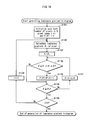
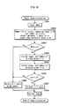
- FIG. 19 is a flowchart showing the operation of the image processing device 100 which is the example of the present invention.
- the image processing unit 100 reads the captured image in the image input unit 110 at first (Step S 3001 ), and then performs initialization such that: the number of all pixels that compose the input image is N; and the number of pixels whose luminance is equal to or larger than the threshold value is M.
- Step S 3003 When a ratio M/N is not larger than a threshold value a (Step S 3003 : N), the image processing unit 100 proceeds to Step S 3009 .
- the image processing unit 100 proceeds to Step S 3004 , and divides the captured image in the image division unit 120 (Step S 3004 ).
- n is defined as the number into which the captured image is divided.
- the area selection unit 130 selects areas in which most of line segments are oriented in the same direction based on the directional characteristics of the textures included in the area determined by the direction judgment unit 125 (Step S 3005 ).
- m is defined as the number of selected areas.
- Step S 3006 When the ratio m/n is not larger than a threshold value ⁇ (Step S 3006 : N), the image processing unit 100 proceeds to Step S 3009 .
- Step S 3007 When the ratio m/n is larger than a threshold value ⁇ (Step S 3006 : Y), the image processing unit 100 proceeds to Step S 3007 , and causes the tilt estimation unit 140 to estimate the tilt angle of the captured image (Step S 3007 ).
- the image correction unit 150 corrects the captured image by rotating the captured image by an amount corresponding to the tilt angle estimated by the tilt estimation unit 140 (Step S 3008 ). However, when it is judged that it is not appropriate to estimate the tilt angle based on the image in Steps S 3003 or S 3006 , the image correction unit 150 causes the sensor to detect the tilt angle (Step S 3009 ), and corrects the captured image with use of the tilt angle.
- the image correction unit 150 since the sensor 160 is not requisite, no processing may be performed on the captured image having insufficient information to estimate the tilt angle if the imaging apparatus does not include the sensor 160 . In such a way, it is possible to prevent the image correction unit 150 from correcting the captured image based on the tilt angle incorrectly estimated, and therefore deterioration in the captured image may be prevented.
- the imaging apparatus includes a sensor 160 , the estimation of the tilt angle using the sensor 160 does not have to be performed, and no processing may be performed on the captured image having insufficient information to estimate the tilt angle if it is difficult to estimate the tilt angle by the sensor 160 .
- an example of cases where it is difficult to estimate the tilt angle by the sensor 160 is a case where an amount of variation in values output by the sensor 160 in a predetermined time period is equal to or larger than a predetermined threshold value. In such a way, it is possible to prevent the image correction unit 150 from correcting the captured image based on the tilt angle incorrectly estimated, and therefore deterioration in the captured image can be prevented.
- the tilt estimation unit 140 may estimate, from the estimated tilt angle of the image captured in the past, the tilt angle of the captured image having insufficient information to estimate the tilt angle by the tilt estimation unit 140 . That is, histories of some of the recently estimated tilt angles of images may be kept, and changes in these tilt angles may be extrapolated, and thus the tilt estimation unit 140 may estimate the tilt angle of the captured image. Also, a tilt angle of the captured image that immediately precedes the tilt angle of the captured image having insufficient information to estimate the tilt angle by the tilt estimation unit 140 may be stored, and such a tilt angle of the captured image may be determined as the tilt angle of the immediately preceding captured image. This is processing based on the assumption that tilt angles of the captured images that have been captured serially change serially if the shaking of the imaging apparatus is small.
- the image processing device selects, from among areas composing the captured image, one or more areas that are suitable for estimating a tilt angle, and estimates the tilt angle based on these areas, it is highly likely to estimate the right tilt angle even if the image is not captured in an upright state.
Landscapes
- Engineering & Computer Science (AREA)
- Physics & Mathematics (AREA)
- General Physics & Mathematics (AREA)
- Theoretical Computer Science (AREA)
- Multimedia (AREA)
- Signal Processing (AREA)
- Computer Vision & Pattern Recognition (AREA)
- Probability & Statistics with Applications (AREA)
- Image Processing (AREA)
- Image Analysis (AREA)
- Studio Devices (AREA)
Abstract
Description
- Patent document 1: Japanese Laid-open Patent Application Publication No. 2003-304486
- Patent document 2: Japanese Patent Publication No. 3676360
-
- 100: image processing device
- 110: image input unit
- 120: image division unit
- 125: direction judgment unit
- 130: area selection unit
- 140: tilt estimation unit
- 150: image correction unit
- 160: sensor
x cos θ+y sin θ=ρ (ρ=x i cos θ+y i sin θ [Equation 9]
Claims (38)
θ=tan−1(Δy/Δx),
Applications Claiming Priority (3)
| Application Number | Priority Date | Filing Date | Title |
|---|---|---|---|
| JP2007183626 | 2007-07-12 | ||
| JP2007-183626 | 2007-07-12 | ||
| PCT/JP2008/001859 WO2009008174A1 (en) | 2007-07-12 | 2008-07-10 | Image processing device, image processing method, image processing program, recording medium with image processing program recorded therein, and image processing processor |
Publications (2)
| Publication Number | Publication Date |
|---|---|
| US20100172598A1 US20100172598A1 (en) | 2010-07-08 |
| US8180176B2 true US8180176B2 (en) | 2012-05-15 |
Family
ID=40228366
Family Applications (1)
| Application Number | Title | Priority Date | Filing Date |
|---|---|---|---|
| US12/602,273 Expired - Fee Related US8180176B2 (en) | 2007-07-12 | 2008-07-10 | Image processing device, image processing method, image processing program, recording medium with image processing program recorded therein, and image processing processor |
Country Status (4)
| Country | Link |
|---|---|
| US (1) | US8180176B2 (en) |
| JP (1) | JP4862080B2 (en) |
| CN (1) | CN101689294B (en) |
| WO (1) | WO2009008174A1 (en) |
Cited By (1)
| Publication number | Priority date | Publication date | Assignee | Title |
|---|---|---|---|---|
| US20100315689A1 (en) * | 2009-06-15 | 2010-12-16 | Canon Kabushiki Kaisha | Image processing apparatus, image processing method, and image processing program recorded recording medium |
Families Citing this family (26)
| Publication number | Priority date | Publication date | Assignee | Title |
|---|---|---|---|---|
| JP2010224987A (en) * | 2009-03-24 | 2010-10-07 | Sharp Corp | Image processing apparatus, image processing method, program, and recording medium |
| GB2470942B (en) * | 2009-06-11 | 2014-07-16 | Snell Ltd | Detection of non-uniform spatial scaling of an image |
| WO2011155161A1 (en) | 2010-06-11 | 2011-12-15 | パナソニック株式会社 | Image processing apparatus and image processing method |
| JP5781743B2 (en) * | 2010-06-28 | 2015-09-24 | ソニー株式会社 | Image processing apparatus, image processing method, and image processing program |
| JP5628596B2 (en) * | 2010-08-24 | 2014-11-19 | 株式会社ブリヂストン | Tire appearance inspection method and appearance inspection apparatus |
| US8411161B2 (en) * | 2010-10-04 | 2013-04-02 | Sony Corporation | Apparatus for automatic estimate of the angle in tilted images for level correction |
| JP5641884B2 (en) * | 2010-11-05 | 2014-12-17 | キヤノン株式会社 | Imaging apparatus and control method thereof |
| US9183633B2 (en) * | 2011-12-21 | 2015-11-10 | Panasonic Intellectual Property Management Co., Ltd. | Image processing apparatus and image processing method |
| JP6137464B2 (en) * | 2013-04-04 | 2017-05-31 | 富士ゼロックス株式会社 | Image processing apparatus and image processing program |
| US9151953B2 (en) * | 2013-12-17 | 2015-10-06 | Amazon Technologies, Inc. | Pointer tracking for eye-level scanners and displays |
| JP6278741B2 (en) * | 2014-02-27 | 2018-02-14 | 株式会社キーエンス | Image measuring instrument |
| JP6290651B2 (en) * | 2014-02-27 | 2018-03-07 | 株式会社キーエンス | Image measuring instrument |
| JP6373664B2 (en) * | 2014-07-09 | 2018-08-15 | 株式会社東芝 | Electronic device, method and program |
| JP6492603B2 (en) * | 2014-12-09 | 2019-04-03 | 日本電気株式会社 | Image processing apparatus, system, image processing method, and program |
| US9800778B2 (en) * | 2015-07-21 | 2017-10-24 | Qualcomm Incorporated | Camera orientation notification system |
| JP6630741B2 (en) * | 2015-12-14 | 2020-01-15 | ヤマハ発動機株式会社 | Vehicle roll angle estimation system, vehicle, vehicle roll angle estimation method and program |
| CN105701786B (en) * | 2016-03-21 | 2019-09-24 | 联想(北京)有限公司 | A kind of image processing method and electronic equipment |
| GB2553103B (en) * | 2016-08-19 | 2022-04-27 | Apical Ltd | Method of angle detection |
| US10652472B2 (en) * | 2018-02-22 | 2020-05-12 | Adobe Inc. | Enhanced automatic perspective and horizon correction |
| US10825241B2 (en) * | 2018-03-16 | 2020-11-03 | Microsoft Technology Licensing, Llc | Using a one-dimensional ray sensor to map an environment |
| JP7130041B2 (en) * | 2018-07-17 | 2022-09-02 | 三菱電機株式会社 | Imaging device |
| CN111583097A (en) * | 2019-02-18 | 2020-08-25 | 北京三星通信技术研究有限公司 | Image processing method, image processing device, electronic equipment and computer readable storage medium |
| CN110312070B (en) * | 2019-04-23 | 2021-08-24 | 维沃移动通信有限公司 | An image processing method and terminal |
| CN112562304B (en) * | 2020-11-26 | 2022-02-18 | 英博超算(南京)科技有限公司 | Interactive system of application layer and sensor data |
| JP7508350B2 (en) * | 2020-12-04 | 2024-07-01 | 株式会社日立製作所 | CALIBRATION APPARATUS AND CALIBRATION METHOD |
| CN114565885B (en) * | 2021-12-14 | 2025-08-26 | 中国铁路上海局集团有限公司科学技术研究所 | A safety detection method for opening and closing door operations of boxcars in railway freight yards |
Citations (12)
| Publication number | Priority date | Publication date | Assignee | Title |
|---|---|---|---|---|
| JPH04177583A (en) | 1990-11-09 | 1992-06-24 | Seiko Epson Corp | Tilt angle detection method |
| JPH06195462A (en) | 1992-12-22 | 1994-07-15 | Fujitsu Ltd | Angle of inclination of image measuring system |
| JPH06215134A (en) | 1993-01-19 | 1994-08-05 | Aisin Seiki Co Ltd | Preprocessing method for on-vehicle picture data to be recognized |
| US5982563A (en) * | 1994-10-28 | 1999-11-09 | Kabushiki Kaisha Toshiba | Projection-type display apparatus |
| US6173088B1 (en) * | 1996-10-01 | 2001-01-09 | Canon Kabushiki Kaisha | Image forming method and apparatus |
| JP2001101399A (en) | 1999-09-28 | 2001-04-13 | Toshiba Corp | Image skew detection / margin detection / skew correction method and document image processing apparatus |
| JP2002092606A (en) | 2000-09-14 | 2002-03-29 | Sharp Corp | Image processing apparatus, image processing method, and recording medium recording the same |
| US20030152291A1 (en) | 2001-06-30 | 2003-08-14 | Cheatle Stephen Philip | Tilt correction of electronic images |
| JP2003304486A (en) | 2002-04-09 | 2003-10-24 | Hitachi Ltd | Storage system and method of selling services using it |
| JP3676360B2 (en) | 2003-02-25 | 2005-07-27 | 松下電器産業株式会社 | Image capture processing method |
| US20060165264A1 (en) * | 2005-01-26 | 2006-07-27 | Hirofumi Saitoh | Method and apparatus for acquiring images, and verification method and verification apparatus |
| US20080240615A1 (en) * | 2007-03-27 | 2008-10-02 | Seiko Epson Corporation | Image processing for image deformation |
Family Cites Families (2)
| Publication number | Priority date | Publication date | Assignee | Title |
|---|---|---|---|---|
| JP3781016B2 (en) * | 2002-06-18 | 2006-05-31 | カシオ計算機株式会社 | Electronic camera, photographing direction acquisition method and program |
| JP3714365B1 (en) * | 2004-03-30 | 2005-11-09 | セイコーエプソン株式会社 | Keystone correction of projector |
-
2008
- 2008-07-10 WO PCT/JP2008/001859 patent/WO2009008174A1/en active Application Filing
- 2008-07-10 JP JP2009522527A patent/JP4862080B2/en not_active Expired - Fee Related
- 2008-07-10 US US12/602,273 patent/US8180176B2/en not_active Expired - Fee Related
- 2008-07-10 CN CN2008800244333A patent/CN101689294B/en active Active
Patent Citations (16)
| Publication number | Priority date | Publication date | Assignee | Title |
|---|---|---|---|---|
| JPH04177583A (en) | 1990-11-09 | 1992-06-24 | Seiko Epson Corp | Tilt angle detection method |
| JPH06195462A (en) | 1992-12-22 | 1994-07-15 | Fujitsu Ltd | Angle of inclination of image measuring system |
| JPH06215134A (en) | 1993-01-19 | 1994-08-05 | Aisin Seiki Co Ltd | Preprocessing method for on-vehicle picture data to be recognized |
| US5982563A (en) * | 1994-10-28 | 1999-11-09 | Kabushiki Kaisha Toshiba | Projection-type display apparatus |
| US6173088B1 (en) * | 1996-10-01 | 2001-01-09 | Canon Kabushiki Kaisha | Image forming method and apparatus |
| US6411743B1 (en) * | 1996-10-01 | 2002-06-25 | Canon Kabushiki Kaisha | Image forming method and apparatus |
| JP2001101399A (en) | 1999-09-28 | 2001-04-13 | Toshiba Corp | Image skew detection / margin detection / skew correction method and document image processing apparatus |
| US20040101209A1 (en) | 2000-09-14 | 2004-05-27 | Hideaki Tanaka | Image processing device, image processing method, and record medium on which the same is recorded |
| JP2002092606A (en) | 2000-09-14 | 2002-03-29 | Sharp Corp | Image processing apparatus, image processing method, and recording medium recording the same |
| US20030152291A1 (en) | 2001-06-30 | 2003-08-14 | Cheatle Stephen Philip | Tilt correction of electronic images |
| JP2004534334A (en) | 2001-06-30 | 2004-11-11 | ヒューレット・パッカード・カンパニー | Method for correcting tilt of electronic image, image processing system, image capturing system, and camera |
| JP2003304486A (en) | 2002-04-09 | 2003-10-24 | Hitachi Ltd | Storage system and method of selling services using it |
| JP3676360B2 (en) | 2003-02-25 | 2005-07-27 | 松下電器産業株式会社 | Image capture processing method |
| US20060165395A1 (en) | 2003-02-25 | 2006-07-27 | Matsushita Electric Industrial Co., Ltd. | Image pickup processing method and image pickup apparatus |
| US20060165264A1 (en) * | 2005-01-26 | 2006-07-27 | Hirofumi Saitoh | Method and apparatus for acquiring images, and verification method and verification apparatus |
| US20080240615A1 (en) * | 2007-03-27 | 2008-10-02 | Seiko Epson Corporation | Image processing for image deformation |
Non-Patent Citations (1)
| Title |
|---|
| International Search Report issued Aug. 12, 2008 in International (PCT) Application No. PCT/JP2008/001859. |
Cited By (2)
| Publication number | Priority date | Publication date | Assignee | Title |
|---|---|---|---|---|
| US20100315689A1 (en) * | 2009-06-15 | 2010-12-16 | Canon Kabushiki Kaisha | Image processing apparatus, image processing method, and image processing program recorded recording medium |
| US8630025B2 (en) * | 2009-06-15 | 2014-01-14 | Canon Kabushiki Kaisha | Image processing apparatus, image processing method, and image processing program recorded recording medium |
Also Published As
| Publication number | Publication date |
|---|---|
| CN101689294B (en) | 2012-07-04 |
| JP4862080B2 (en) | 2012-01-25 |
| CN101689294A (en) | 2010-03-31 |
| WO2009008174A1 (en) | 2009-01-15 |
| JPWO2009008174A1 (en) | 2010-09-02 |
| US20100172598A1 (en) | 2010-07-08 |
Similar Documents
| Publication | Publication Date | Title |
|---|---|---|
| US8180176B2 (en) | Image processing device, image processing method, image processing program, recording medium with image processing program recorded therein, and image processing processor | |
| CN101690166B (en) | Camera device, method, system integrated circuit | |
| EP2582127B1 (en) | Image processing apparatus and image processing method | |
| US8532420B2 (en) | Image processing apparatus, image processing method and storage medium storing image processing program | |
| JP3600755B2 (en) | Face image processing device | |
| JP4816725B2 (en) | Image processing apparatus, image processing program, electronic camera, and image processing method for image analysis of lateral chromatic aberration | |
| JP5258859B2 (en) | Runway estimation apparatus and program | |
| RU2621480C1 (en) | Device for evaluating moving body position and method for evaluating moving body position | |
| US20080292192A1 (en) | Human detection device and method and program of the same | |
| US20090290809A1 (en) | Image processing device, image processing method, and program | |
| US9183633B2 (en) | Image processing apparatus and image processing method | |
| WO2012172817A1 (en) | Image stabilization apparatus, image stabilization method, and document | |
| US9224212B2 (en) | Image processing apparatus and image processing method | |
| CN113822942A (en) | Method for measuring object size by monocular camera based on two-dimensional code | |
| CN107292828B (en) | Image edge processing method and device | |
| US20090207260A1 (en) | Image pickup apparatus and image pickup method | |
| CN114124397B (en) | Method and apparatus for determining the authenticity of a video | |
| US20110286659A1 (en) | Image Processing Apparatus, Image Processing Method, and Computer Program | |
| US20120148104A1 (en) | Pedestrian-crossing marking detecting method and pedestrian-crossing marking detecting device | |
| CN105915785A (en) | Double-camera shadedness determining method and device, and terminal | |
| US7602943B2 (en) | Image processing apparatus, image processing method, and image processing program | |
| JP6492603B2 (en) | Image processing apparatus, system, image processing method, and program | |
| CN109496326B (en) | Image processing method, device and system | |
| KR101101139B1 (en) | Image Quality Evaluation Method and Apparatus Using Motif Scan | |
| JP2001006084A (en) | Vehicle end point detection method |
Legal Events
| Date | Code | Title | Description |
|---|---|---|---|
| AS | Assignment |
Owner name: PANASONIC CORPORATION, JAPAN Free format text: ASSIGNMENT OF ASSIGNORS INTEREST;ASSIGNOR:KIMURA, MASAYUKI;REEL/FRAME:023849/0072 Effective date: 20091109 |
|
| FEPP | Fee payment procedure |
Free format text: PAYOR NUMBER ASSIGNED (ORIGINAL EVENT CODE: ASPN); ENTITY STATUS OF PATENT OWNER: LARGE ENTITY |
|
| ZAAA | Notice of allowance and fees due |
Free format text: ORIGINAL CODE: NOA |
|
| ZAAB | Notice of allowance mailed |
Free format text: ORIGINAL CODE: MN/=. |
|
| STCF | Information on status: patent grant |
Free format text: PATENTED CASE |
|
| AS | Assignment |
Owner name: PANASONIC INTELLECTUAL PROPERTY CORPORATION OF AME Free format text: ASSIGNMENT OF ASSIGNORS INTEREST;ASSIGNOR:PANASONIC CORPORATION;REEL/FRAME:033033/0163 Effective date: 20140527 Owner name: PANASONIC INTELLECTUAL PROPERTY CORPORATION OF AMERICA, CALIFORNIA Free format text: ASSIGNMENT OF ASSIGNORS INTEREST;ASSIGNOR:PANASONIC CORPORATION;REEL/FRAME:033033/0163 Effective date: 20140527 |
|
| FPAY | Fee payment |
Year of fee payment: 4 |
|
| MAFP | Maintenance fee payment |
Free format text: PAYMENT OF MAINTENANCE FEE, 8TH YEAR, LARGE ENTITY (ORIGINAL EVENT CODE: M1552); ENTITY STATUS OF PATENT OWNER: LARGE ENTITY Year of fee payment: 8 |
|
| AS | Assignment |
Owner name: PIECE FUTURE PTE LTD, SINGAPORE Free format text: ASSIGNMENT OF ASSIGNORS INTEREST;ASSIGNOR:PANASONIC CORPORATION;REEL/FRAME:051591/0587 Effective date: 20200116 |
|
| AS | Assignment |
Owner name: IMAGIXE LIMITED, HONG KONG Free format text: ASSIGNMENT OF ASSIGNORS INTEREST;ASSIGNOR:PIECE FUTURE PTE. LTD.;REEL/FRAME:053544/0576 Effective date: 20190825 |
|
| FEPP | Fee payment procedure |
Free format text: MAINTENANCE FEE REMINDER MAILED (ORIGINAL EVENT CODE: REM.); ENTITY STATUS OF PATENT OWNER: LARGE ENTITY |
|
| LAPS | Lapse for failure to pay maintenance fees |
Free format text: PATENT EXPIRED FOR FAILURE TO PAY MAINTENANCE FEES (ORIGINAL EVENT CODE: EXP.); ENTITY STATUS OF PATENT OWNER: LARGE ENTITY |
|
| STCH | Information on status: patent discontinuation |
Free format text: PATENT EXPIRED DUE TO NONPAYMENT OF MAINTENANCE FEES UNDER 37 CFR 1.362 |
|
| FP | Lapsed due to failure to pay maintenance fee |
Effective date: 20240515 |