US10825241B2 - Using a one-dimensional ray sensor to map an environment - Google Patents
Using a one-dimensional ray sensor to map an environment Download PDFInfo
- Publication number
- US10825241B2 US10825241B2 US15/924,025 US201815924025A US10825241B2 US 10825241 B2 US10825241 B2 US 10825241B2 US 201815924025 A US201815924025 A US 201815924025A US 10825241 B2 US10825241 B2 US 10825241B2
- Authority
- US
- United States
- Prior art keywords
- point
- points
- computing device
- map
- wearable computing
- Prior art date
- Legal status (The legal status is an assumption and is not a legal conclusion. Google has not performed a legal analysis and makes no representation as to the accuracy of the status listed.)
- Active
Links
Images


Classifications
-
- G—PHYSICS
- G06—COMPUTING; CALCULATING OR COUNTING
- G06T—IMAGE DATA PROCESSING OR GENERATION, IN GENERAL
- G06T17/00—Three dimensional [3D] modelling, e.g. data description of 3D objects
- G06T17/05—Geographic models
-
- G—PHYSICS
- G01—MEASURING; TESTING
- G01S—RADIO DIRECTION-FINDING; RADIO NAVIGATION; DETERMINING DISTANCE OR VELOCITY BY USE OF RADIO WAVES; LOCATING OR PRESENCE-DETECTING BY USE OF THE REFLECTION OR RERADIATION OF RADIO WAVES; ANALOGOUS ARRANGEMENTS USING OTHER WAVES
- G01S7/00—Details of systems according to groups G01S13/00, G01S15/00, G01S17/00
- G01S7/48—Details of systems according to groups G01S13/00, G01S15/00, G01S17/00 of systems according to group G01S17/00
- G01S7/481—Constructional features, e.g. arrangements of optical elements
- G01S7/4817—Constructional features, e.g. arrangements of optical elements relating to scanning
-
- G—PHYSICS
- G01—MEASURING; TESTING
- G01S—RADIO DIRECTION-FINDING; RADIO NAVIGATION; DETERMINING DISTANCE OR VELOCITY BY USE OF RADIO WAVES; LOCATING OR PRESENCE-DETECTING BY USE OF THE REFLECTION OR RERADIATION OF RADIO WAVES; ANALOGOUS ARRANGEMENTS USING OTHER WAVES
- G01S17/00—Systems using the reflection or reradiation of electromagnetic waves other than radio waves, e.g. lidar systems
- G01S17/02—Systems using the reflection of electromagnetic waves other than radio waves
- G01S17/06—Systems determining position data of a target
- G01S17/08—Systems determining position data of a target for measuring distance only
- G01S17/10—Systems determining position data of a target for measuring distance only using transmission of interrupted, pulse-modulated waves
-
- G—PHYSICS
- G01—MEASURING; TESTING
- G01S—RADIO DIRECTION-FINDING; RADIO NAVIGATION; DETERMINING DISTANCE OR VELOCITY BY USE OF RADIO WAVES; LOCATING OR PRESENCE-DETECTING BY USE OF THE REFLECTION OR RERADIATION OF RADIO WAVES; ANALOGOUS ARRANGEMENTS USING OTHER WAVES
- G01S17/00—Systems using the reflection or reradiation of electromagnetic waves other than radio waves, e.g. lidar systems
- G01S17/88—Lidar systems specially adapted for specific applications
- G01S17/89—Lidar systems specially adapted for specific applications for mapping or imaging
-
- G—PHYSICS
- G06—COMPUTING; CALCULATING OR COUNTING
- G06T—IMAGE DATA PROCESSING OR GENERATION, IN GENERAL
- G06T2210/00—Indexing scheme for image generation or computer graphics
- G06T2210/04—Architectural design, interior design
Definitions
- alternate realities e.g., augmented, virtual, or mixed realities
- An exemplary approach to developing maps or blueprints of the user's surroundings include employing expensive sensors and hardware that provide real-time surface reconstruction of the user's environment. This approach can be expensive and at times produce imperfect results.
- a wearable device implements a one-dimensional depth sensor, such as a LIDAR (Light Detection and Ranging) system, which is statically affixed to the wearable device and passively scans a physical environment, generates and stores points from the scan, and builds a blueprint for the physical environment, in which the blueprints are gradually built as the user navigates the area.
- the wearable device can include any one of a head-mounted display device, watch, head phones, and the like.
- the depth sensor is configured to continuously operate and detect the physical environment that the user navigates. To reduce cost, the depth sensor may operate in a fixed position on the wearable device and scan along a single axis; thus, the depth sensor operates and builds the environment according to the user's movements, position, and gaze direction.
- the depth sensor and wearable device are configured to generate a blueprint or map of the negative space in the user's environment using a point cloud structure based on the points derived from the depth sensor.
- the negative space for the blueprints include permanent structures such as walls, floors, countertops, ceilings, doorways, and the like.
- the wearable device is configured to distinguish between temporary (or movable) objects (e.g., a chair, pet, person, toys, etc.) from permanent structures. This way, a reliable blueprint of the building's architecture is generated without cluttering the blueprint or wasting unnecessary system memory and resources for transitory items.
- the wearable device may first identify its location within the physical environment. Although the depth sensor itself can be used to recognize its location within the point cloud structure, other available sensor devices such as GPS, Wi-Fi (e.g., fingerprinting, triangulation, etc.), among others, can be used to help determine the location. Once position is known, these devices can be switched off to save power consumption, in which the wearable device can rely on the depth sensor for its location at that point forward. These localization devices can be used again if location becomes an issue, the wearable device is switched off, moves to a new location, etc.
- GPS GPS
- Wi-Fi e.g., fingerprinting, triangulation, etc.
- Each point that the depth sensor generates represents a corresponding point in the physical environment.
- Each point is stored in a point cloud structure with defined coordinates (e.g., XYZ coordinates) for surface reconstruction of the environment.
- the depth sensor or map building application assigns a timestamp to each generated point so that points that are not verified within a pre-set time frame are set to expire.
- Generated points for locations that do not exist in memory are considered new, and therefore stored in memory.
- Generated points for locations within the point cloud structure that are currently associated with pre-existing points are updated or discarded depending on the scenario.
- the wearable device may use the subsequent point due to its recency, or alternatively, may maintain the pre-existing point if there is no discernable change.
- the subsequent point may be discarded, or alternatively, may replace the pre-existing point.
- the subsequent point may be discarded when the reliability of the pre-existing point satisfies a threshold.
- the pre-existing point may replace it.
- the pre-existing point may be unreliable when it is believed to be associated with a temporary object as opposed to a permanent structure.
- the wearable device continues to update and supplement the point cloud structure and blueprints with newly detected points.
- the completed blueprints can be useful for the wearable device itself, local applications on the wearable device, or for extensibility beyond the wearable device.
- resource-intensive hardware components on the wearable device can be disabled or switched off, such as components that provide location information for the user. Since the user's relative location within the physical environment is known from the developed blueprints, some of these resource-intensive and power-consuming components can be temporarily disabled.
- Such components can include Wi-Fi transceivers, location components like GPS (Global Positioning System), or other depth sensors (in embodiments where multiple depth sensors are implemented) to detect the physical environment.
- the single-axis depth sensor and wearable device provide a low-cost and low-power method to identify and develop the user's physical environment and thereby generate reliable blueprints.
- the wearable device may stitch together pre-existing points with subsequent points.
- multiple user environments can be stitched together to form blueprints to expedite the development process of the map.
- the wearable device can utilize the collective points among multiple users to formulate the blueprints.
- FIG. 1 shows an illustrative system architecture of a wearable device
- FIG. 2 shows illustrative components of an exemplary depth sensor using a LIDAR system
- FIG. 3 shows an illustrative environment of computing devices interacting over a network
- FIG. 4 shows an illustrative diagram of a created point and associations with the point
- FIG. 5 shows illustrative operations after a passive scan by the depth sensor
- FIG. 6 shows an illustrative original point picked up by the depth sensor
- FIG. 7 shows an illustrative subsequent point picked up by the depth sensor
- FIG. 8 shows an illustrative lifespan of a point
- FIG. 9 shows an illustrative real-world layout of a physical environment
- FIG. 10 shows an illustrative initial blueprint for the physical environment of FIG. 9 ;
- FIG. 11 shows an illustrative development of the blueprint after a walkthrough by a user wearing the wearable device
- FIG. 12 shows an illustrative gradual development of the blueprint after a subsequent walkthrough by the user wearing the wearable device
- FIG. 13 shows an illustrative completed blueprint after N number of walkthroughs by the user wearing the wearable device
- FIG. 14 shows an illustrative taxonomy of functions or uses of the blueprint for the wearable device or other computing devices
- FIGS. 15-17 show illustrative processes performed by one or more wearable devices or computing devices
- FIG. 18 a simplified block diagram of an illustrative wearable device that may be used in part to implement the use of the one-dimensional ray sensor to map an environment
- FIG. 19 is a simplified block diagram of an illustrative computer system that may be used in part to implement the use of the one-dimensional ray sensor to map an environment.
- FIG. 1 shows an illustrative system architecture 100 of a wearable device 105 .
- the wearable device 105 may include one or more of a variety of different computing devices that are configured to be readily and conveniently worn by the user to enable various functionalities and provide beneficial user experiences.
- the wearable device 105 may be implemented using components that are donned like eyeglass, caps, gloves, headbands, headsets, hats, helmets, earbuds, shoes, wristbands, and belts, and/or be positioned on the user's body using attachments like neck straps, arm/leg straps, lanyards, and the like.
- Wearable devices may also be incorporated or embedded into clothing (as indicated by the dashed lines in FIG. 1 ).
- wearable devices may be configured to provide hands-free and eyes-free experiences as the device operates, using battery power to facilitate portability and mobility.
- wearable device 105 Various types of user interfaces may be utilized by the wearable device 105 including displays and inputs systems. Some wearable devices may be operated through voice interaction and sensed gestures and/or user activity. Wearable devices may be configured to operate continuously in a non-intrusive manner and may also support functionalities and user experiences that rely on explicit user interactions or other user inputs. The wearable device may be further configured with communication and networking interfaces to enable it to interact with either or both local and remote users, devices, systems, services, and resources.
- the wearable device 105 is configured to include various sensors, as described below, that may be configured to detect and/or measure motion, light, surfaces, temperature, humidity, location, altitude, and other parameters that are descriptive of the user or device environment.
- Other sensors may be supported on the wearable device which are positioned directly or indirectly on the user's body to monitor parameters that are descriptive of the user's physiological state such as movement, body and/or body part position or pose, pulse, skin temperature, and the like.
- the sensors may be operated in various combinations so that a given descriptive parameter may, in some cases, be derived by suitable systems in the wearable device using data from more than one sensor, or by combining sensor data with other information that is available to the device.
- the architecture 100 is conceptually arranged in layers and includes a hardware layer 120 , operating system (OS) layer 115 , and application layer 110 .
- the hardware layer 120 provides an abstraction of the various hardware used by the wearable device 105 (e.g., input and output devices, networking and radio hardware, etc.) to the layers above it.
- the hardware layer supports processor(s) 125 , memory 130 , transceiver (e.g., network connectivity hardware) 135 , a depth sensor 140 , other sensory devices (e.g., Inertial Measurement Unit (IMU)) 145 , and input/output, speakers, microphones, buttons, and the like (not shown).
- the wearable device depicts various components 155 which can represent the hardware components in the hardware layer.
- the representation of depth sensor 140 on the wearable device is exemplary and other such locations on the wearable device are also possible.
- FIG. 2 shows illustrative components of an exemplary depth sensor 140 using a Light Detection and Ranging (LIDAR) system.
- LIDAR measures distance to a target and builds an image that represents external surface properties of a target or physical environment.
- LIDAR transmits laser pulses and scans properties of the reflected laser pulses to build point cloud data points based on XYZ coordinates, in which the point cloud data points represent an external surface of a target object or physical environment.
- the point cloud data points or structure may be stored in memory either locally, at a remote service, or a combination thereof.
- reference to points herein pertain to the data points generated from LIDAR or other depth sensor, each point of which represents a scanned point of the real-world and physical environment.
- Typical components of LIDAR include a processor 205 to build the image based on scanned reflective properties, laser transmitter 210 (e.g., ultraviolet, visible or infrared), scanners and optics 215 (e.g., fixed position scanner/sensor), receiver electronics 220 (e.g., photodetector or solid state detector), and positioning and orientation system (POS) 225 (e.g., GPS and IMU).
- the POS may provide the location and orientation (e.g., pitch, yaw, roll) for the LIDAR to sense and generate points for coordinates.
- the LIDAR may use local or remote components for the POS, in which the projected ray from the scanner can be performed regardless of where or how POS is calculated.
- the wearable device may be configured as a beacon that is detected from external components, such as a camera, which can therefore externally detect the POS characteristics of the wearable device.
- LIDAR is shown in FIG. 2 as the implemented depth sensor, alternative sensors which can be used in alternative embodiments include RADAR (Radio Detection and Ranging), ultrasonic systems, and passive visual systems.
- the application layer 110 in this illustrative example supports various applications 160 , including an application configured to build blueprints 165 as discussed herein.
- the application to build blueprints can use the point cloud data points from the LIDAR, or other depth sensor, to build the physical environment around the user in a map.
- the blueprints are built over time upon each occurrence in which the user navigates an environment. New data points that are currently undiscovered within the physical environment supplement or update the point cloud structure to create a reliable and complete blueprint for an environment over time.
- FIG. 1 Other applications not shown can include a web browser configured to provide connectivity to the world wide web, games, etc. Although only certain applications are depicted in FIG. 1 , any number of applications can be utilized by the wearable device, whether proprietary or developed by third-parties. The applications are often implemented using locally executing code. However, in some cases these applications can rely on services and/or remote code execution provided by remote servers or other computing platforms such as those supported by a service provider or other cloud-based resources ( FIG. 3 ).
- the OS layer 115 supports, among other operations, managing system 170 and operating applications 175 , such as operate the build blueprint application 165 (as illustratively shown by the arrow).
- the OS layer may interoperate with the application and hardware layers in order to perform various functions and features.
- FIG. 3 shows an illustrative environment 300 in which a user 305 operates the wearable device 105 , and the wearable device is configured to interoperate with external computing devices such as a remote maps service 310 and client device 315 over network 320 .
- the network can include any number and combination of local area network, wide area network, the Internet, or the World Wide Web.
- the external computing devices can interoperate with an extensibility client 330 of the build blueprint application 165 , in which the external computing devices can, in whole or in part, build the blueprints upon receiving the collected data points from the wearable device's depth sensor. Therefore, any discussion with respect to the development of blueprints and a point cloud structure using generated points can be local to the wearable device, external thereto at external computing devices, or a combination thereof.
- an external maps service 325 may communicate with the maps service 310 or other computing devices shown in FIG. 3 .
- the external maps service can store external maps that represent the user's physical environment which are different from the developed blueprints. These external maps may include maps previously built using surface reconstruction techniques, maps directly input by a user, maps obtained from public or private sources, etc.
- the external maps service may use the blueprints derived from the wearable device to verify and/or update content within these external maps, or vice versa. Thus, if an external map depicts floorplans for an office building which places a wall at a location contrary to the developed blueprint, then the external map may be updated accordingly, either with a correction to the external map itself or a notation that the map may be inaccurate.
- the environment 300 may include multiple users and wearable devices configured like wearable device 105 , as representatively shown by reference numerals 305 n and 105 n .
- Blueprints can be built using data points derived from a single user or multiple users.
- the maps service 310 may combine and share developed blueprints and point cloud structures derived from a multitude of users. Since the present system develops the blueprints over time, additional users navigating an environment allows greater opportunities for depth sensors to capture points of the user's physical environment, and thereby hastens the process and shortens the time period for the blueprints to develop.
- FIG. 4 shows an illustrative high-level diagram 400 in which the various hardware components ( FIGS. 1 and 2 ) are utilized to develop a point 405 for the point cloud structure.
- the depth sensor e.g., LIDAR
- POS 225 e.g., POS 225
- processor 125 e.g., POS 225
- clock 410 e.g., POS 225 , processor 125 , and clock 410 are configured to generate individual points and point characteristics which correspond to scanned points in the physical environment.
- Each point or group of points is assigned a timestamp 415 (e.g., a date and time the point is generated), a location 420 (e.g., using a coordinate system such as XYZ coordinates), and content 425 .
- timestamp 415 e.g., a date and time the point is generated
- location 420 e.g., using a coordinate system such as XYZ coordinates
- content 425 e.
- the content 425 can provide an indication or inference as to whether the point or group of points is associated with a permanent structure 430 or temporary object 435 .
- the present system is configured to build blueprints for negative space defined by permanent structures associated with the physical environment, such as walls, floors, ceilings, doorways, beams, structural support, windows, foyers and other structural surface characteristics. Therefore, temporary and movable objects, such as people, pets, toys, chairs, waste baskets, and the like may be discarded from the developed blueprints. Criteria may be utilized to distinguish between temporary objects and permanent structures, such as by comparing pre-existing points to newly generated points.
- FIG. 5 shows an exemplary diagram 500 of a passive scan 505 performed by the depth sensor and subsequent processing performed for each generated point.
- the scan may be passive in that it performs a one-dimensional scan along a single axis according to the direction in which the user faces.
- the passive scan along a single axis may be utilized to reduce cost, weight, and power consumption of the wearable device and save real estate by using quantitatively less sensors.
- multiple depth sensors configured to perform two- or three-dimensional scans along two or three axes can be performed to scan a greater number of points.
- the depth sensor may perform the passive scan when the depth sensor or wearable device's location is known.
- localization techniques can include using, with notice to the user and user consent, one or more of GPS, Wi-Fi fingerprinting or other Wi-Fi localization techniques using signal strength, Bluetooth® beaconing, and the like. Once the location of the wearable device is known, these additional localization components can be switched off to save battery power, but can be switched on again if the depth sensor has trouble identifying its relative location. In order to identify its location, the depth sensor can use a developed point cloud structure to locate its position and orientation using scanned data points.
- the wearable device may update a pre-existing point 510 , store a new point 515 , increase a reliability count for a point 520 , or perform other operations as represented by the ellipsis. Any one or more of these operations may be performed for each point.
- Each point may be assigned a timestamp 525 , which can occur at any stage of the process (e.g., before, or contemporaneous with, operations at numerals 510 , 515 , and 520 ).
- the timestamp may be assigned by the depth sensor or the processor during development of the blueprint.
- the wearable device may update a pre-existing point if the generated point shares or conflicts with a location of the pre-existing point in the point cloud structure.
- the wearable device may store a new point if no corresponding point currently exists in the point cloud structure. Whether the generated point updates a pre-existing point or is stored as a new point, a reliability count may be incremented.
- the reliability count represents a confidence value that the point is accurate. For example, a pre-existing point that has been verified several times based on subsequent scans provides a relatively strong indication that the point is accurate and that the point is not associated with a transitory or temporary object.
- FIGS. 6 and 7 show illustrative sequential environments where a point generated from a previous scan changes during a subsequent scan.
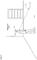
- the user 305 operates the wearable device 105 which projects a one-dimensional ray at a dog 605 in the direction of the user's gaze.
- the dog represents a transitory object.
- the depth sensor detects that the location (e.g. coordinates) for a point 610 is elevated above the floor 615 and stores the point in the point cloud structure.
- FIG. 7 represents a temporally subsequent scan, such as later that day, the next day, or the following week, in which the dog is no longer present.
- This scan the location for the point changed as shown in the different locations for pre-existing point 610 and subsequent point 705 .
- the subsequent point 705 represents a location on the floor 615 .
- the wearable device may delete the pre-existing point 610 and update the point cloud structure with the subsequent point 705 .
- a reliability counter may be refreshed for point 705 since the pre-existing point has been deleted.
- Differences in point locations may be identified based on the depth sensor's position and orientation systems and utilization of the point cloud structure. For example, the position and orientation systems identify a similar angle and location under similar circumstances between FIGS. 6 and 7 .
- the point cloud structure may have indicated that the location for point 705 previously represented a surface several inches or feet above the floor ( FIG. 6 ), which was contrary to current data.
- the position and orientation systems and point cloud structure together indicate distances, differences, and similarities between points.
- points that represent a permanent structure may be maintained if a subsequent scan shows a different point location.
- a subsequent scan shows a different point location.
- the reliability increases for points associated with permanent structures by confidence measures such as the reliability counter. Therefore, transitory objects that are picked up by subsequent scans may be discarded when reliability for a pre-existing point surpasses a threshold (e.g., five verifications for the pre-existing point).
- certain points may be outliers when compared with a group of points, and thereby discarded.
- algorithms that compare adjacent or surrounding points can provide indications as to whether a certain point is an outlier (e.g., transitory), or comports with the layout of other known points.
- FIG. 8 shows an illustrative diagram 800 in which the wearable device initiates a decay process of a point 805 after expiration of the point's lifetime using the point's assigned timestamp 525 .
- all points may be assigned a pre-set lifetime during a previous scan 810 .
- the previous scan may be an initial scan of a point or may be temporally prior to a subsequent scan 825 .
- the pre-set lifetime may be a date and time for the point to expire or a timer that counts down. If the point is not verified 815 before expiration of the lifetime, such as picked up in a subsequent scan, the wearable device initiates a decay process 820 of the point.
- the decay process can include deleting the point upon expiration of its lifetime.
- the subsequent scan 825 may pick up and generate a point that corresponds to the point 805 , in which case the point 805 becomes pre-existing.
- the wearable device increases the reliability counter for the pre-existing point, updates the point's timestamp 830 , confirms that the point is verified 815 , and maintains the point in the point cloud structure 835 .
- the point may continue to be assigned a pre-set lifetime that requires verification.
- the pre-set lifetime may be assigned when the reliability counter or confidence value for a point has not met a threshold.
- a point may stop being assigned a lifetime if its reliability counter (e.g., a reliability counter of seven) or confidence value satisfies a threshold value.
- FIGS. 9-14 show exemplary diagrams for a physical environment for which blueprints gradually develop over time.
- FIG. 9 shows an actual layout of an exemplary physical environment 900 , such as an office building, home, store, etc.
- FIG. 10 shows an initial blueprint of the negative space for the environment 900 which is stored in memory. The wearable device has not yet formulated or developed a blueprint for the environment since the wearable device has yet to navigate the space.
- FIGS. 11-13 show the gradual development of the blueprint for the layout in FIG. 9 .
- FIG. 11 shows an initial development of the negative space blueprint represented as permanent or non-transient structures (e.g., floor and walls) after a first walkthrough by the user.
- FIG. 12 shows the gradual development of the negative space during one or more subsequent walkthroughs.
- FIG. 13 shows a virtually completed blueprint after N number of walkthroughs.
- Blueprints may continue to develop over long periods of time, such as weeks, months, or years.
- the development of the blueprints depends on the amount of time the user navigates through a building and the extent of the user's coverage of the building. For example, a user who navigates many areas of a physical space may cause the wearable device to develop blueprints for an environment relatively quicker than a user who only traverses a single hallway or portion of a physical space.
- the development progression depicted in FIGS. 11-13 may be based on different times the user navigated the defined space of the environment. For example, a user with his wearable device may navigate the area one day and subsequently depart the defined area. When the user subsequently returns to that same defined area, such as later that day, the next day, or weeks, months, or years later, the point cloud structure and blueprint will continue to develop and build on top of the previously generated points. This process repeats itself so the blueprints continue to develop over time.
- FIG. 14 shows an illustrative taxonomy of functions 1405 for which blueprints can be used.
- the various functions may be utilized while the map is currently in development or when the map is completed beyond a threshold level.
- the threshold level may be a percentage (e.g., 75%, 90%, etc.) of completion of a room, building, or defined area.
- the wearable device may disable resource intensive components 1410 , which thereby allows the wearable device to enter a low-power state. For example, if multiple depth sensors are implemented to capture points for the environment, one or more of the depth sensors may be switched off or disabled since the physical environment is sufficiently known.
- the wearable device may disable certain positioning or orientation sensors (e.g., Wi-Fi transceiver, GPS, or IMU) since the wearable device can rely more heavily on the developed blueprints.
- Additional functionality provided by the blueprints include extensibility to other applications (e.g., location-aware applications) 1415 , determining wearable's or user's location within the blueprint 1420 , comparing, verifying, or combining blueprints with external maps 1425 , combining blueprints with additional knowledge of the space 1430 , determining location of objects within the blueprints 1435 , or showing location of objects within the blueprints 1440 .
- applications e.g., location-aware applications
- FIG. 15 is a flowchart of an illustrative method 1500 in which a wearable device updates a blueprint of a physical environment. Unless specifically stated, methods or steps shown in the flowcharts and described in the accompanying text are not constrained to a particular order or sequence. In addition, some of the methods or steps thereof can occur or be performed concurrently and not all the methods or steps have to be performed in a given implementation depending on the requirements of such implementation and some methods or steps may be optionally utilized.
- a location is identified for the wearable device.
- the location can be identified using GPS, the user's position relative to a Wi-Fi access point, among other options.
- original depth data is received from a depth sensor.
- a negative space blueprint is developed for the physical environment at the identified location using the original depth data. The developed blueprint is based on points collected by the depth sensor.
- the blueprint of the physical environment is updated as the depth sensor collects new depth data, in which pre-existing points are updated and presently undiscovered points are stored.
- FIG. 16 is a flowchart of an illustrative method 1600 which the wearable device may employ to differentiate between temporary or transient objects and permanent structures.
- a location for a wearable device is identified.
- an orientation associated with the wearable device is determined.
- points are collected using a one-dimensional sensor, in which the sensor continually picks up points as the wearable device navigates an area.
- the wearable device may navigate an area, for example, while the user wears the wearable device and walks around a room.
- the collected points and location and orientation information are used to build a map of an area surrounding the wearable device, in which the map distinguishes between objects and permanent structures.
- Permanent structures are desired since the wearable device seeks to build a map of the physical environment that has future utility. That is, storing knowledge of the current location of a pet or chair may have little use in the future when those objects move. Thus, the system seeks to identify negative space of the objects in the form of permanent structures, such as walls, ceilings, doorways, structural support, beams, etc.
- FIG. 17 is a flowchart of an illustrative method 1700 in which a computing device, such as a wearable device, discards points which represent transient structures and updates a point cloud structure as the device continues to receive point data.
- a computing device such as a wearable device
- point data is periodically received from a depth sensor.
- each point or group of points is timestamped.
- a map of negative space is built using the point data, in which the map represents non-transient structures.
- point data which represents transient structures are discarded.
- a map or a point cloud structure is updated as the point data is periodically received.
- FIG. 18 shows an illustrative architecture 1800 for a device capable of executing the various components described herein for providing the present user and device authentication for web applications.
- the architecture 1800 illustrated in FIG. 18 shows an architecture that may be adapted for a wearable device, a server computer, mobile phone, a PDA, a smartphone, a desktop computer, a netbook computer, a tablet computer, GPS device, gaming console, and/or a laptop computer.
- the architecture 1800 may be utilized to execute any aspect of the components presented herein.
- the architecture 1800 illustrated in FIG. 18 includes one or more processors 1802 (e.g., central processing unit, graphic processing units, etc.), a system memory 1804 , including RAM (random access memory) 1806 and ROM (read only memory) 1808 , and a system bus 1810 that operatively and functionally couples the components in the architecture 1800 .
- processors 1802 e.g., central processing unit, graphic processing units, etc.
- system memory 1804 including RAM (random access memory) 1806 and ROM (read only memory) 1808
- a system bus 1810 that operatively and functionally couples the components in the architecture 1800 .
- the architecture 1800 further includes a mass storage device 1812 for storing software code or other computer-executed code that is utilized to implement applications, the file system, and the operating system.
- the mass storage device 1812 is connected to the processor 1802 through a mass storage controller (not shown) connected to the bus 1810 .
- the mass storage device 1812 and its associated computer-readable storage media provide non-volatile storage for the architecture 1800 .
- computer-readable storage media can be any available storage media that can be accessed by the architecture 1800 .
- the architecture 1800 further supports a sensor package 1830 comprising one or more sensors or components that are configured to detect parameters that are descriptive of the environment and/or detect parameters that are descriptive of the device user, or combinations therein.
- the sensors may be positioned directly or indirectly on the user's body.
- the sensors may be configured to run continuously, or periodically, and typically in hands-free and/or eyes-free manners.
- the architecture further supports power and/or battery components (collectively identified by reference numeral 1815 ).
- one or more batteries or power packs may be rechargeable or replaceable to facilitate portability and mobility.
- computer-readable storage media may include volatile and non-volatile, removable and non-removable media implemented in any method or technology for storage of information such as computer-readable instructions, data structures, program modules, or other data.
- computer-readable media includes, but is not limited to, RAM, ROM, EPROM (erasable programmable read only memory), EEPROM (electrically erasable programmable read only memory), Flash memory or other solid state memory technology, CD-ROM, DVDs, HD-DVD (High Definition DVD), Blu-ray, or other optical storage, magnetic cassettes, magnetic tape, magnetic disk storage or other magnetic storage devices, or any other medium which can be used to store the desired information and which can be accessed by the architecture 1800 .
- the architecture 1800 may operate in a networked environment using logical connections to remote computers through a network.
- the architecture 1800 may connect to the network through a network interface unit 1816 connected to the bus 1810 .
- the network interface unit 1816 also may be utilized to connect to other types of networks and remote computer systems.
- the architecture 1800 also may include an input/output controller 1818 for receiving and processing input from a number of other devices, including a keyboard, mouse, touchpad, touchscreen, control devices such as buttons and switches or electronic stylus (not shown in FIG. 18 ).
- the input/output controller 1818 may provide output to a display screen, user interface a printer, or other type of output device (also not shown in FIG. 18 ).
- the architecture 1800 may include a voice recognition unit (not shown) to facilitate user interaction with a device supporting the architecture through voice commands, a natural language interface, or through voice interactions with a personal digital assistant (such as the Cortana® personal digital assistant provided by Microsoft Corporation).
- the architecture 1800 may include a gesture recognition unit (not shown) to facilitate user interaction with a device supporting the architecture through sensed gestures, movements, and/or other sensed inputs.
- the software components described herein may, when loaded into the processor 1802 and executed, transform the processor 1802 and the overall architecture 1800 from a general-purpose computing system into a special-purpose computing system customized to facilitate the functionality presented herein.
- the processor 1802 may be constructed from any number of transistors or other discrete circuit elements, which may individually or collectively assume any number of states. More specifically, the processor 1802 may operate as a finite-state machine, in response to executable instructions contained within the software modules disclosed herein. These computer-executable instructions may transform the processor 1802 by specifying how the processor 1802 transitions between states, thereby transforming the transistors or other discrete hardware elements constituting the processor 1802 .
- Encoding the software modules presented herein also may transform the physical structure of the computer-readable storage media presented herein.
- the specific transformation of physical structure may depend on various factors, in different implementations of this description. Examples of such factors may include, but are not limited to, the technology used to implement the computer-readable storage media, whether the computer-readable storage media is characterized as primary or secondary storage, and the like.
- the computer-readable storage media is implemented as semiconductor-based memory
- the software disclosed herein may be encoded on the computer-readable storage media by transforming the physical state of the semiconductor memory.
- the software may transform the state of transistors, capacitors, or other discrete circuit elements constituting the semiconductor memory.
- the software also may transform the physical state of such components in order to store data thereupon.
- the computer-readable storage media disclosed herein may be implemented using magnetic or optical technology.
- the software presented herein may transform the physical state of magnetic or optical media, when the software is encoded therein. These transformations may include altering the magnetic characteristics of particular locations within given magnetic media. These transformations also may include altering the physical features or characteristics of particular locations within given optical media to change the optical characteristics of those locations. Other transformations of physical media are possible without departing from the scope and spirit of the present description, with the foregoing examples provided only to facilitate this discussion.
- the architecture 1800 may include other types of computing devices, including wearable devices, handheld computers, embedded computer systems, smartphones, PDAs, and other types of computing devices known to those skilled in the art. It is also contemplated that the architecture 1800 may not include all of the components shown in FIG. 18 , may include other components that are not explicitly shown in FIG. 18 , or may utilize an architecture completely different from that shown in FIG. 18 .
- FIG. 19 is a simplified block diagram of an illustrative computer system 1900 such as a wearable device with which the present use of a one-dimensional ray sensor to map an environment may be implemented.
- Computer system 1900 includes a processor 1905 , a system memory 1911 , and a system bus 1914 that couples various system components including the system memory 1911 to the processor 1905 .
- the system bus 1914 may be any of several types of bus structures including a memory bus or memory controller, a peripheral bus, or a local bus using any of a variety of bus architectures.
- the system memory 1911 includes read only memory (ROM) 1917 and random access memory (RAM) 1921 .
- a basic input/output system (BIOS) 1925 containing the basic routines that help to transfer information between elements within the computer system 1900 , such as during startup, is stored in ROM 1917 .
- the computer system 1900 may further include a hard disk drive 1928 for reading from and writing to an internally disposed hard disk (not shown), a magnetic disk drive 1930 for reading from or writing to a removable magnetic disk 1933 (e.g., a floppy disk), and an optical disk drive 1938 for reading from or writing to a removable optical disk 1943 such as a CD (compact disc), DVD (digital versatile disc), or other optical media.
- this illustrative example includes a hard disk, a removable magnetic disk 1933 , and a removable optical disk 1943
- other types of computer-readable storage media which can store data that is accessible by a computer such as magnetic cassettes, Flash memory cards, digital video disks, data cartridges, random access memories (RAMs), read only memories (ROMs), and the like may also be used in some applications of the present use of a one-dimensional ray sensor to map an environment.
- the term computer-readable storage media includes one or more instances of a media type (e.g., one or more magnetic disks, one or more CDs, etc.).
- the phrase “computer-readable storage media” and variations thereof are non-transitory and do not include waves, signals, and/or other transitory and/or intangible communication media.
- a number of program modules may be stored on the hard disk, magnetic disk, optical disk, ROM 1917 , or RAM 1921 , including an operating system 1955 , one or more application programs 1957 , other program modules 1960 , and program data 1963 .
- a user may enter commands and information into the computer system 1900 through input devices such as a keyboard 1966 and pointing device 1968 such as a mouse.
- Other input devices may include a microphone, joystick, game pad, satellite dish, scanner, trackball, touchpad, touchscreen, touch-sensitive device, voice-command module or device, user motion or user gesture capture device, or the like.
- the computer system 1900 is operable in a networked environment using logical connections to one or more remote computers, such as a remote computer 1988 .
- the remote computer 1988 may be selected as a personal computer, a server, a router, a network PC, a peer device, or other common network node, and typically includes many or all of the elements described above relative to the computer system 1900 , although only a single representative remote memory/storage device 1990 is shown in FIG. 19 .
- the logical connections depicted in FIG. 19 include a local area network (LAN) 1993 and a wide area network (WAN) 1995 .
- LAN local area network
- WAN wide area network
- Such networking environments are often deployed, for example, in offices, enterprise-wide computer networks, intranets, and the Internet.
- the computer system 1900 When used in a LAN networking environment, the computer system 1900 is connected to the local area network 1993 through a network interface or adapter 1996 .
- the computer system 1900 When used in a WAN networking environment, the computer system 1900 typically includes a broadband modem 1998 , network gateway, or other means for establishing communications over the wide area network 1995 , such as the Internet.
- the broadband modem 1998 which may be internal or external, is connected to the system bus 1914 via a serial port interface 1971 .
- program modules related to the computer system 1900 may be stored in the remote memory storage device 1990 . It is noted that the network connections shown in FIG. 19 are illustrative and other means of establishing a communications link between the computers may be used depending on the specific requirements of an application of the present use of a one-dimensional ray sensor to map an environment.
- An example includes a wearable device, comprising: one or more processors; a single axis depth sensor affixed in a fixed position to the wearable device configured to passively scan and generate one-dimensional depth data for a physical environment; and memory having computer-readable instructions which, when executed by the one or more processors, cause the wearable device to: identify a location for the wearable device; receive original depth data from the depth sensor; develop a negative space blueprint for the physical environment at the identified location using the original depth data, the blueprint being based on points collected by the depth sensor; and update the blueprint of the physical environment as the depth sensor collects new depth data, in which pre-existing points from the original depth data are updated using the new depth data and undiscovered points of the physical environment are stored using the new depth data.
- the instructions further cause the wearable device to: assign timestamps to points relative to being collected by the wearable device; when a point is not timely verified, initiate a decay process in which the unverified point is deleted from the blueprint; and when a point is timely verified, maintain the point within the blueprint.
- points are assigned a pre-set lifetime that runs based on the assignment of the timestamp, and the decay process for the points initiate when the points are not verified before expiration of the pre-set lifetime.
- points are verified when collected within the new depth data.
- the instructions further cause the wearable device to assign confidence values to points within the blueprint, the confidence values indicating a greater likelihood that a point is negative space and not a temporary object.
- the instructions further cause the wearable device to: use a reliability counter for each point; and increase the reliability counter when coordinates for a point identified in the new depth data correspond to coordinates for a pre-existing point from the original depth data, in which the confidence value for points increases relative to increases to the counter.
- a further example includes a method performed by a wearable device or a computing device in communication with the wearable device over a network: identifying a location associated with the wearable device; determining an orientation associated with the wearable device; collecting points from a one-dimensional ray sensor affixed to the wearable device, in which the sensor continually picks up points as the wearable device navigates an area; and using the collected points and the location and orientation information, building a map of an area surrounding the wearable device, in which the map distinguishes between objects and permanent structures such that permanent structures are included in the map and objects are discarded.
- permanent structures include walls, ceilings, floors, or support beams.
- objects that are discarded are movable or temporary objects within the area.
- the method further comprises replacing an original point within a point cloud image when subsequent point data indicates that the original point represented a temporary object.
- the method further comprises not replacing an original point within a point cloud image when subsequent point data represents a temporary object.
- the method further comprises reducing functionality of one or more components on the wearable device when the area in the map associated with the wearable device's current location is sufficiently developed beyond a threshold.
- reducing functionality includes switching off or disabling functions or components on the wearable device.
- the one or more components include any one or more of a processor, radio transmitter, Global Positioning System (GPS), or sensor.
- a further example includes one or more hardware-based computer-readable memory devices storing instructions which, when executed by one or more processors disposed in a computing device, cause the computing device to: periodically receive point data directly or indirectly from a depth sensor; timestamp each point or group of points in the point data; build a map of negative space representing non-transient structures using the point data; discard the point data which represents transient structures; and update the map or a point cloud structure as point data is periodically received at temporally different times, in which updating the map or the point cloud structure includes at least one of: i) increasing a count associated with a point when the point in subsequent point data corresponds to a point in previous point data; and ii) replacing a point in previous point data with a point in subsequent point data.
Abstract
Description
Claims (18)
Priority Applications (2)
| Application Number | Priority Date | Filing Date | Title |
|---|---|---|---|
| US15/924,025 US10825241B2 (en) | 2018-03-16 | 2018-03-16 | Using a one-dimensional ray sensor to map an environment |
| PCT/US2019/021511 WO2019177915A1 (en) | 2018-03-16 | 2019-03-09 | Using a one-dimensional ray sensor to map an environment |
Applications Claiming Priority (1)
| Application Number | Priority Date | Filing Date | Title |
|---|---|---|---|
| US15/924,025 US10825241B2 (en) | 2018-03-16 | 2018-03-16 | Using a one-dimensional ray sensor to map an environment |
Publications (2)
| Publication Number | Publication Date |
|---|---|
| US20190287296A1 US20190287296A1 (en) | 2019-09-19 |
| US10825241B2 true US10825241B2 (en) | 2020-11-03 |
Family
ID=65895063
Family Applications (1)
| Application Number | Title | Priority Date | Filing Date |
|---|---|---|---|
| US15/924,025 Active US10825241B2 (en) | 2018-03-16 | 2018-03-16 | Using a one-dimensional ray sensor to map an environment |
Country Status (2)
| Country | Link |
|---|---|
| US (1) | US10825241B2 (en) |
| WO (1) | WO2019177915A1 (en) |
Families Citing this family (3)
| Publication number | Priority date | Publication date | Assignee | Title |
|---|---|---|---|---|
| CN112688991B (en) * | 2020-12-15 | 2022-11-04 | 北京百度网讯科技有限公司 | Method for performing point cloud scanning operation, related apparatus and storage medium |
| CN112835518B (en) * | 2021-01-27 | 2023-04-25 | 歌尔科技有限公司 | Data storage method and device, wearable device and storage medium |
| US20230053106A1 (en) * | 2021-08-03 | 2023-02-16 | Strap Technologies Inc | Sensor-actuator and artificial intelligence-based wearable device system and methods |
Citations (24)
| Publication number | Priority date | Publication date | Assignee | Title |
|---|---|---|---|---|
| US6646725B1 (en) * | 2001-07-11 | 2003-11-11 | Iowa Research Foundation | Multiple beam lidar system for wind measurement |
| US20040230552A1 (en) * | 2003-05-13 | 2004-11-18 | Microsoft Corporation | Removal of stale information |
| US20090323121A1 (en) * | 2005-09-09 | 2009-12-31 | Robert Jan Valkenburg | A 3D Scene Scanner and a Position and Orientation System |
| US20100172598A1 (en) * | 2007-07-12 | 2010-07-08 | Masayuki Kimura | Image processing device, image processing method, image processing program, recording medium with image processing program recorded therein, and image processing processor |
| US20130120736A1 (en) | 2010-07-26 | 2013-05-16 | Commonwealth Scientic And Industrial Research Organisation | Three dimensional scanning beam system and method |
| US20140145914A1 (en) * | 2012-11-29 | 2014-05-29 | Stephen Latta | Head-mounted display resource management |
| US8818124B1 (en) * | 2011-03-04 | 2014-08-26 | Exelis, Inc. | Methods, apparatus, and systems for super resolution of LIDAR data sets |
| US20140301633A1 (en) * | 2013-04-09 | 2014-10-09 | Google Inc. | System and Method for Floorplan Reconstruction and Three-Dimensional Modeling |
| US20150362587A1 (en) | 2014-06-17 | 2015-12-17 | Microsoft Corporation | Lidar sensor calibration using surface pattern detection |
| US20160005229A1 (en) | 2014-07-01 | 2016-01-07 | Samsung Electronics Co., Ltd. | Electronic device for providing map information |
| US20160063332A1 (en) | 2014-08-27 | 2016-03-03 | Toyota Jidosha Kabushiki Kaisha | Communication of external sourced information to a driver |
| WO2016041088A1 (en) | 2014-09-19 | 2016-03-24 | Sulon Technologies Inc. | System and method for tracking wearable peripherals in augmented reality and virtual reality applications |
| US9317133B2 (en) | 2010-10-08 | 2016-04-19 | Nokia Technologies Oy | Method and apparatus for generating augmented reality content |
| US20160210785A1 (en) | 2013-10-03 | 2016-07-21 | Sulon Technologies Inc. | Augmented reality system and method for positioning and mapping |
| US20160291134A1 (en) | 2015-04-06 | 2016-10-06 | Google Inc. | Long Range Steerable LIDAR System |
| US20170124396A1 (en) * | 2015-10-29 | 2017-05-04 | Hand Held Products, Inc. | Dynamically created and updated indoor positioning map |
| US9753950B2 (en) * | 2013-03-15 | 2017-09-05 | Pictometry International Corp. | Virtual property reporting for automatic structure detection |
| US20170256096A1 (en) * | 2016-03-07 | 2017-09-07 | Google Inc. | Intelligent object sizing and placement in a augmented / virtual reality environment |
| WO2017151778A1 (en) | 2016-03-01 | 2017-09-08 | ARIS MD, Inc. | Systems and methods for rendering immersive environments |
| US20170300973A1 (en) | 2016-04-19 | 2017-10-19 | Wal-Mart Stores, Inc. | Systems, apparatuses, and method for mapping a space |
| US20180188043A1 (en) * | 2016-12-30 | 2018-07-05 | DeepMap Inc. | Classification of surfaces as hard/soft for combining data captured by autonomous vehicles for generating high definition maps |
| US20180190017A1 (en) * | 2017-01-04 | 2018-07-05 | Daqri, Llc | Environmental Mapping System |
| US20180259966A1 (en) * | 2017-03-13 | 2018-09-13 | Nio Usa, Inc. | Navigation of autonomous vehicles to enhance safety under one or more fault conditions |
| US20180316901A1 (en) * | 2017-04-26 | 2018-11-01 | Ford Global Technologies, Llc | Event reconstruct through image reporting |
-
2018
- 2018-03-16 US US15/924,025 patent/US10825241B2/en active Active
-
2019
- 2019-03-09 WO PCT/US2019/021511 patent/WO2019177915A1/en active Application Filing
Patent Citations (24)
| Publication number | Priority date | Publication date | Assignee | Title |
|---|---|---|---|---|
| US6646725B1 (en) * | 2001-07-11 | 2003-11-11 | Iowa Research Foundation | Multiple beam lidar system for wind measurement |
| US20040230552A1 (en) * | 2003-05-13 | 2004-11-18 | Microsoft Corporation | Removal of stale information |
| US20090323121A1 (en) * | 2005-09-09 | 2009-12-31 | Robert Jan Valkenburg | A 3D Scene Scanner and a Position and Orientation System |
| US20100172598A1 (en) * | 2007-07-12 | 2010-07-08 | Masayuki Kimura | Image processing device, image processing method, image processing program, recording medium with image processing program recorded therein, and image processing processor |
| US20130120736A1 (en) | 2010-07-26 | 2013-05-16 | Commonwealth Scientic And Industrial Research Organisation | Three dimensional scanning beam system and method |
| US9317133B2 (en) | 2010-10-08 | 2016-04-19 | Nokia Technologies Oy | Method and apparatus for generating augmented reality content |
| US8818124B1 (en) * | 2011-03-04 | 2014-08-26 | Exelis, Inc. | Methods, apparatus, and systems for super resolution of LIDAR data sets |
| US20140145914A1 (en) * | 2012-11-29 | 2014-05-29 | Stephen Latta | Head-mounted display resource management |
| US9753950B2 (en) * | 2013-03-15 | 2017-09-05 | Pictometry International Corp. | Virtual property reporting for automatic structure detection |
| US20140301633A1 (en) * | 2013-04-09 | 2014-10-09 | Google Inc. | System and Method for Floorplan Reconstruction and Three-Dimensional Modeling |
| US20160210785A1 (en) | 2013-10-03 | 2016-07-21 | Sulon Technologies Inc. | Augmented reality system and method for positioning and mapping |
| US20150362587A1 (en) | 2014-06-17 | 2015-12-17 | Microsoft Corporation | Lidar sensor calibration using surface pattern detection |
| US20160005229A1 (en) | 2014-07-01 | 2016-01-07 | Samsung Electronics Co., Ltd. | Electronic device for providing map information |
| US20160063332A1 (en) | 2014-08-27 | 2016-03-03 | Toyota Jidosha Kabushiki Kaisha | Communication of external sourced information to a driver |
| WO2016041088A1 (en) | 2014-09-19 | 2016-03-24 | Sulon Technologies Inc. | System and method for tracking wearable peripherals in augmented reality and virtual reality applications |
| US20160291134A1 (en) | 2015-04-06 | 2016-10-06 | Google Inc. | Long Range Steerable LIDAR System |
| US20170124396A1 (en) * | 2015-10-29 | 2017-05-04 | Hand Held Products, Inc. | Dynamically created and updated indoor positioning map |
| WO2017151778A1 (en) | 2016-03-01 | 2017-09-08 | ARIS MD, Inc. | Systems and methods for rendering immersive environments |
| US20170256096A1 (en) * | 2016-03-07 | 2017-09-07 | Google Inc. | Intelligent object sizing and placement in a augmented / virtual reality environment |
| US20170300973A1 (en) | 2016-04-19 | 2017-10-19 | Wal-Mart Stores, Inc. | Systems, apparatuses, and method for mapping a space |
| US20180188043A1 (en) * | 2016-12-30 | 2018-07-05 | DeepMap Inc. | Classification of surfaces as hard/soft for combining data captured by autonomous vehicles for generating high definition maps |
| US20180190017A1 (en) * | 2017-01-04 | 2018-07-05 | Daqri, Llc | Environmental Mapping System |
| US20180259966A1 (en) * | 2017-03-13 | 2018-09-13 | Nio Usa, Inc. | Navigation of autonomous vehicles to enhance safety under one or more fault conditions |
| US20180316901A1 (en) * | 2017-04-26 | 2018-11-01 | Ford Global Technologies, Llc | Event reconstruct through image reporting |
Non-Patent Citations (2)
| Title |
|---|
| "International Search Report and Written Opinion Issued in PCT Application No. PCT/US19/021511", dated Jun. 21, 2019, 12 Pages. |
| Bosse, et al. "Continuous 3D Scan-Matching with a Spinning 2D Laser", In Proceedings of The 2009 IEEE International Conference on Robotics and Automation, May 12, 2009, 8 Pages. |
Also Published As
| Publication number | Publication date |
|---|---|
| WO2019177915A1 (en) | 2019-09-19 |
| US20190287296A1 (en) | 2019-09-19 |
Similar Documents
| Publication | Publication Date | Title |
|---|---|---|
| WO2019109729A1 (en) | Bone posture determining method and device, and computer readable storage medium | |
| CN107077548B (en) | Virtual wearable object | |
| US10571279B2 (en) | Object and location tracking with a graph-of-graphs | |
| US9807725B1 (en) | Determining a spatial relationship between different user contexts | |
| US11573325B2 (en) | Systems and methods for improvements in scanning and mapping | |
| CN109421067A (en) | Robot virtual boundary | |
| US10825241B2 (en) | Using a one-dimensional ray sensor to map an environment | |
| US20170094018A1 (en) | Facilitating dynamic filtering and local and/or remote processing of data based on privacy policies and/or user preferences | |
| WO2018068771A1 (en) | Target tracking method and system, electronic device, and computer storage medium | |
| US10631118B2 (en) | Maintaining privacy in location-based operations | |
| US10715468B2 (en) | Facilitating tracking of targets and generating and communicating of messages at computing devices | |
| US20160080911A1 (en) | Accounting for indoor-outdoor transitions during position determination | |
| CN106164982A (en) | Electronic equipment positioning based on image | |
| Hardegger et al. | 3D ActionSLAM: wearable person tracking in multi-floor environments | |
| JP2017047519A (en) | Cloud robotics system, information processor, program, and method for controlling or supporting robot in cloud robotics system | |
| CN103620620A (en) | Using spatial information in device interaction | |
| US20140378166A1 (en) | Method, storage medium, server, and electronic device for implementing location based service within building | |
| CN106575162A (en) | Facilitating dynamic eye torsion-based eye tracking on computing devices | |
| US10602056B2 (en) | Optimal scanning trajectories for 3D scenes | |
| Khan et al. | Recent advances in vision-based indoor navigation: A systematic literature review | |
| JP6127564B2 (en) | Touch determination device, touch determination method, and touch determination program | |
| US10573273B2 (en) | Method and system for device placement based optimization techniques | |
| US20210357620A1 (en) | System, moving object, and information processing apparatus | |
| US9756475B2 (en) | Mobile terminal and method for controlling place recognition | |
| KR20170100281A (en) | Electronic device for determining position and method for operating thereof |
Legal Events
| Date | Code | Title | Description |
|---|---|---|---|
| FEPP | Fee payment procedure |
Free format text: ENTITY STATUS SET TO UNDISCOUNTED (ORIGINAL EVENT CODE: BIG.); ENTITY STATUS OF PATENT OWNER: LARGE ENTITY |
|
| AS | Assignment |
Owner name: MICROSOFT TECHNOLOGY LICENSING, LLC, WASHINGTON Free format text: ASSIGNMENT OF ASSIGNORS INTEREST;ASSIGNORS:YORK, KENDALL CLARK;SIPKO, JEFFREY;HESKETH, JOHN BENJAMIN;AND OTHERS;SIGNING DATES FROM 20180316 TO 20180321;REEL/FRAME:045310/0314 Owner name: MICROSOFT TECHNOLOGY LICENSING, LLC, WASHINGTON Free format text: ASSIGNMENT OF ASSIGNORS INTEREST;ASSIGNOR:HAWTHORNE, BRYANT DANIEL;REEL/FRAME:045320/0732 Effective date: 20180322 |
|
| STPP | Information on status: patent application and granting procedure in general |
Free format text: RESPONSE TO NON-FINAL OFFICE ACTION ENTERED AND FORWARDED TO EXAMINER |
|
| STPP | Information on status: patent application and granting procedure in general |
Free format text: FINAL REJECTION MAILED |
|
| STPP | Information on status: patent application and granting procedure in general |
Free format text: DOCKETED NEW CASE - READY FOR EXAMINATION |
|
| STPP | Information on status: patent application and granting procedure in general |
Free format text: NON FINAL ACTION MAILED |
|
| STPP | Information on status: patent application and granting procedure in general |
Free format text: NOTICE OF ALLOWANCE MAILED -- APPLICATION RECEIVED IN OFFICE OF PUBLICATIONS |
|
| STPP | Information on status: patent application and granting procedure in general |
Free format text: PUBLICATIONS -- ISSUE FEE PAYMENT VERIFIED |
|
| STCF | Information on status: patent grant |
Free format text: PATENTED CASE |