US8112956B2 - Frame construction arrangement forming an opening in a wall of a low-rise building - Google Patents
Frame construction arrangement forming an opening in a wall of a low-rise building Download PDFInfo
- Publication number
- US8112956B2 US8112956B2 US12/729,395 US72939510A US8112956B2 US 8112956 B2 US8112956 B2 US 8112956B2 US 72939510 A US72939510 A US 72939510A US 8112956 B2 US8112956 B2 US 8112956B2
- Authority
- US
- United States
- Prior art keywords
- frame
- panel
- steel
- wall
- girder
- Prior art date
- Legal status (The legal status is an assumption and is not a legal conclusion. Google has not performed a legal analysis and makes no representation as to the accuracy of the status listed.)
- Expired - Fee Related
Links
Images


Classifications
-
- E—FIXED CONSTRUCTIONS
- E04—BUILDING
- E04B—GENERAL BUILDING CONSTRUCTIONS; WALLS, e.g. PARTITIONS; ROOFS; FLOORS; CEILINGS; INSULATION OR OTHER PROTECTION OF BUILDINGS
- E04B1/00—Constructions in general; Structures which are not restricted either to walls, e.g. partitions, or floors or ceilings or roofs
- E04B1/02—Structures consisting primarily of load-supporting, block-shaped, or slab-shaped elements
- E04B1/08—Structures consisting primarily of load-supporting, block-shaped, or slab-shaped elements the elements consisting of metal
-
- E—FIXED CONSTRUCTIONS
- E04—BUILDING
- E04B—GENERAL BUILDING CONSTRUCTIONS; WALLS, e.g. PARTITIONS; ROOFS; FLOORS; CEILINGS; INSULATION OR OTHER PROTECTION OF BUILDINGS
- E04B1/00—Constructions in general; Structures which are not restricted either to walls, e.g. partitions, or floors or ceilings or roofs
- E04B1/18—Structures comprising elongated load-supporting parts, e.g. columns, girders, skeletons
- E04B1/24—Structures comprising elongated load-supporting parts, e.g. columns, girders, skeletons the supporting parts consisting of metal
- E04B1/2403—Connection details of the elongated load-supporting parts
- E04B2001/2415—Brackets, gussets, joining plates
-
- E—FIXED CONSTRUCTIONS
- E04—BUILDING
- E04B—GENERAL BUILDING CONSTRUCTIONS; WALLS, e.g. PARTITIONS; ROOFS; FLOORS; CEILINGS; INSULATION OR OTHER PROTECTION OF BUILDINGS
- E04B1/00—Constructions in general; Structures which are not restricted either to walls, e.g. partitions, or floors or ceilings or roofs
- E04B1/18—Structures comprising elongated load-supporting parts, e.g. columns, girders, skeletons
- E04B1/24—Structures comprising elongated load-supporting parts, e.g. columns, girders, skeletons the supporting parts consisting of metal
- E04B1/2403—Connection details of the elongated load-supporting parts
- E04B2001/2448—Connections between open section profiles
-
- E—FIXED CONSTRUCTIONS
- E04—BUILDING
- E04B—GENERAL BUILDING CONSTRUCTIONS; WALLS, e.g. PARTITIONS; ROOFS; FLOORS; CEILINGS; INSULATION OR OTHER PROTECTION OF BUILDINGS
- E04B1/00—Constructions in general; Structures which are not restricted either to walls, e.g. partitions, or floors or ceilings or roofs
- E04B1/18—Structures comprising elongated load-supporting parts, e.g. columns, girders, skeletons
- E04B1/24—Structures comprising elongated load-supporting parts, e.g. columns, girders, skeletons the supporting parts consisting of metal
- E04B1/2403—Connection details of the elongated load-supporting parts
- E04B2001/2457—Beam to beam connections
-
- E—FIXED CONSTRUCTIONS
- E04—BUILDING
- E04B—GENERAL BUILDING CONSTRUCTIONS; WALLS, e.g. PARTITIONS; ROOFS; FLOORS; CEILINGS; INSULATION OR OTHER PROTECTION OF BUILDINGS
- E04B1/00—Constructions in general; Structures which are not restricted either to walls, e.g. partitions, or floors or ceilings or roofs
- E04B1/18—Structures comprising elongated load-supporting parts, e.g. columns, girders, skeletons
- E04B1/24—Structures comprising elongated load-supporting parts, e.g. columns, girders, skeletons the supporting parts consisting of metal
- E04B1/2403—Connection details of the elongated load-supporting parts
- E04B2001/2463—Connections to foundations
-
- E—FIXED CONSTRUCTIONS
- E04—BUILDING
- E04B—GENERAL BUILDING CONSTRUCTIONS; WALLS, e.g. PARTITIONS; ROOFS; FLOORS; CEILINGS; INSULATION OR OTHER PROTECTION OF BUILDINGS
- E04B1/00—Constructions in general; Structures which are not restricted either to walls, e.g. partitions, or floors or ceilings or roofs
- E04B1/18—Structures comprising elongated load-supporting parts, e.g. columns, girders, skeletons
- E04B1/24—Structures comprising elongated load-supporting parts, e.g. columns, girders, skeletons the supporting parts consisting of metal
- E04B2001/2496—Shear bracing therefor
Definitions
- the present invention relates to a frame construction for a low-rise building of one to three stories having a large opening such as a doorway or a window, and/or for a large span low-rise building of, e.g., one to three stories having a large opening such as a doorway or a window.
- a steel frame work method (hereinafter referred to as a first prior art method) has been mainly employed as a construction method for a low-rise building of one to three stories in the prior art
- a steel house construction method has recently been prevalent.
- the steel house is defined as a building of a steel panel structure composed of frame members made of thin lightweight section steel and construction surface members or braces.
- This construction method is referred to as a second prior art method hereinafter.
- FIGS. 16 to 18 An example of a single-storied building constructed by the first prior art method (the steel frame work method) is illustrated in FIGS. 16 to 18 .
- Individual footings 1 and a floor (a stall) 2 are constructed from concrete.
- the features of the first example are as follows.
- a material cost for the roof is low; the number of parts is low; manufacturing is easy; site work is easy in that one day is sufficient for erecting a building for a convenience store or the like; the opening is freely prepared (if necessary, studs may be used in accordance with a width of the opening); and only cutting of the constituent members is needed.
- drawbacks thereof are that the precision of execution of work is liable to vary; LGS (light-gage steel) is necessary as a substrate for finishing the wall; and site work needs two days.
- FIGS. 19 to 21 illustrate another example of a single-storied building for a convenience store or the like constructed by the second prior art method (the steel house (SH) method).
- a continuous footing 8 and a floor (a stall) 2 are constructed from concrete, and wall frame panels 9 made of thin light-gauge section steel are stood on the continuous footing 8 .
- the wall frame panel 9 is formed by standing vertical frame members 11 of thin light-gauge section steel on a lower frame member 10 of thin light-gauge section steel, placing an upper frame member 12 of thin light-gauge section steel on the vertical frame members 11 , and fixing a construction surface member 13 to the respective frame members with drill screws 19 .
- the product obtained by fixing the construction surface member 13 to the respective frame members is referred to as an SH panel 9 .
- a truss 14 of thin light-gauge section steel (hereinafter referred to as an SH truss) is assembled to be supported by the wall frame panel 9 , and a roof 6 is supported by the SH truss 14 .
- reference numeral 15 denotes a relatively large opening (e.g., a window or a doorway).
- FIGS. 20(B) and 20(C) illustrate examples of the lintel 16 , in which lipped channels 16 a of thin steel sheet are opposed to each other and the outside thereof is reinforced with a reinforcement channel(s) 18 .
- FIGS. 20(D) and 20(E) illustrate another example, in which opposite flanges of the lintel bracket 17 of a U-shaped thin steel plate as seen in a plan view are brought into contact with lateral sides of an end of the lintel 16 and fixed to each other with drill screws 19 , and a web is brought into contact with a back side of the vertical frame members 11 and fixed to each other with drill screws 19 .
- the steel house is constructed by using the frame members of thin light-gauge section steel as main frame elements, to which wood frame members are partially combined or a surface member of plywood is used as a construction surface member if necessary.
- the frame member of thin light-gauge section steel is formed by shaping a thin steel sheet of approximately 1 mm thick, through roll-forming, to be a channel, a lipped channel or a box so that a width or others thereof is matched with a predetermined specification.
- FIGS. 22 to 25 A further example of a frame construction according to the second prior art method is illustrated in FIGS. 22 to 25 .
- a plurality of vertical frame members 11 are provided from lower frame members 10 at a distance between the adjacent ones thereof, and the upper ends of the respective vertical frame members 11 are coupled by upper frame members 12 .
- Wall frame panels (force-resisting wall panels) 9 are formed by attaching construction surface members 13 (see FIGS. 24 and 25 ) or braces to the wall frame members constructed by the lower frame members 10 , the vertical frame members 11 and the upper frame members 12 . Openings 15 such as a doorway 7 or a window 7 a are formed in the building.
- Side beams 5 b and end beams 5 c are supported by the upper frame members 12 of the wall frame panel (force-resisting wall panel) 9 so that both the beams are combined to form a rectangle.
- a plurality of beams 5 c of various lengths are provided in parallel to the side at a predetermined distance.
- Opposite ends of the longer beam 5 d are coupled to the front and rear end beams 5 c via brackets 20 , while one end of the shorter beam 5 d is coupled to the front or rear end beam 5 c and the other end thereof is coupled to a girder 5 a via brackets 11 , respectively.
- a floor panel 2 is constructed by covering the beams 5 d with the construction surface members 13 of plywood or the like.
- reference numeral 5 e denotes an end beam in the floor opening
- 5 f denotes a side beam in the opening
- 20 a denotes a beam bracket
- 20 b denotes a cleat.
- the lintel 16 is provided above the opening 15 .
- an upper frame member 12 and a lintel frame member 16 b are provided above and beneath the lintel 16 of the window 7 a , respectively.
- Upper frame members 12 a of the opening are provided between the lintel frame member 16 b and upper frame member 16 c of the window, and opposite ends of the lintel 16 are attached to lintel receiving members 16 d via the lintel brackets 17 , and vertical frame members 11 a for attaching the lintel brackets are coupled to the vertical frame members 11 at ends of the force-resisting wall 9 by drill screws 19 .
- Reference numeral 7 b denotes a window base
- 7 c denotes a window base
- 10 a denotes a lower frame member of the opening.
- FIG. 24 schematically illustrates an opening 15 of a building formed of a ground floor portion 36 constructed by the SH method and a second floor portion 37 placed on the former
- FIG. 25 illustrates a section taken along a line A-A in FIG. 24
- Each of the drawings shows a connection structure between the lintel 16 , the end beam 5 c and the beam 5 d .
- An end of the beam 5 d having the bracket 20 is coupled to the end beam 5 c made of thin light-gauge section steel.
- the bracket 20 is formed by cutting a lipped channel of thin light-gauge section steel into short pieces and disposing it so that the channel portion is in the vertical direction.
- the lintel 16 arranged beneath the end beam 5 c and coupled thereto by drill screws is formed by opposing the lipped thin light-gauge channels 16 a to each other and fixing the upper and lower sides thereof by connection frame members 16 d.
- a skeleton is constructed of the force-resisting wall panels (SH panels) constructed by the wall frame members which are formed by assembling the frame members of thin light-gauge section steel by using the drill screws and are coupled to the construction surface members also by using the drill screws.
- SH panels force-resisting wall panels
- the merit thereof is that the thin light-gauge section steel necessitates no welding, and is easily cut and drilled, as well as it also being light in weight and capable of being manually conveyed, whereby the working efficiency is high and the manufacturing cost is low.
- SH panel force-resisting wall panel
- the period of erection is half of a day, and in a two or three storied building of approximately 99 to 132 m 2 , the period of erection is two days. Accordingly, this construction method is economical in the field of low-rise buildings.
- the second prior art method (steel house (SH) method), however, has the following drawbacks. For example, in the building for a convenience store or the like, it is required that a large opening is formed on the wall surface and the number of columns is reduced to as small as possible to ensure a large space.
- the lintel is provided in the upper portion of the opening to distribute the vertical load, applied to the opening from above, to the opposite vertical frames of the force-resisting wall panel.
- the lintel is required to have a strength capable of withstanding a vertical load, from above, such as the load of a roof or a floor.
- the lintel preferably uses a member in which a plurality of thin light-gauge section steel pieces are combined to result in the complexity of the manufacture and construction of the lintel.
- the attachment of the lintel to the peripheral members becomes complex in relation to complexity in the structure of the lintel.
- the height of the opening i.e., reference h provided in FIG. 24
- the lintel can be restricted due to the existence of the lintel.
- One of the objects of the present invention is to provide a frame construction for a low-rise building in which the above-mentioned problem has been solved.
- frame construction may be preferably free from the drawbacks of the SH method while maintaining the advantages of a steel house for a low-rise building (for example, a single or two to three-storied building for a convenience store), which partially adopts a heavyweight steel frame structure (hereinafter referred to as a mixed construction) or a frame member construction consisting of a plurality of thin light-gauge section steels coupled together (hereinafter referred to as a composite construction).
- a mixed construction a heavyweight steel frame structure
- a composite construction consisting of a plurality of thin light-gauge section steels coupled together
- Another object of the present invention is to provide frame construction which maintains the advantage of the frame members of thin light-gauge section steel used in the SH method in that it is light in weight and capable of being manually conveyed; and eliminating the drawback thereof in that it is inferior in strength, by combining the same with heavyweight section steel which is inferior in execution property and heavy in weight.
- the frame construction for the low-rise building having features of both the frame member made of thin light-gauge section steel and the heavyweight section steel.
- the lintel is generally not used in the opening, but the force-resisting wall panel and the roof panel or the floor panel can be coupled together via the girder provided in the upper portion of the force-resisting wall panel.
- a frame construction is provided, which require no time for processing the lintel and is free from a restriction in the height of the opening.
- a frame construction for a low-rise building is provided.
- a wall frame panel structured from a lower frame member, an upper frame member and vertical frame members of thin light-gauge section steel is coupled to a girder of heavyweight steel provided at the upper end of the wall frame panel by a coupling arrangement comprising bolts and/or hold-down fasteners.
- a reinforcement steek column may also be provide.
- the wall frame panel can be structured by fixing a construction surface member or a brace to the lower frame member, the upper frame member and the vertical frame members.
- the girder may be formed of channel steel, and the channel steel can be coupled to the upper frame member of the wall frame panel by bolts.
- the girder may also be formed of H-shaped steel, and the H-shaped steel is coupled to the upper frame member of the wall frame panel by bolts.
- the channel steel may be coupled to the upper frame member of the wall frame panel by bolts via a hold down fastener disposed s that a horizontal member is on the upper side, and/or the H-shaped steel can be coupled to the upper fram member of the wall fram panel by bolts via a hold-down fastener disposed so that a horizontal member is on the upper side.
- the problem of the thin light-gauge section steel may be solved by combining the same with heavyweight section steel, while maintaining the merit thereof in that it is light in weight and capable of being manually conveyed, it is possible to smoothly support a roof load by a simple construction based on the steel house method without using a complicated structure such as a roof truss or others.
- the exemplary embodiments of the present invention may solve the following problem which may be inherent to the steel house method: e.g., (i) a cost for constructing a roof is high because it may be necessary to form a truss in the roof portion because the cross-section of the frame member of thin light-gauge channel is thin, resulting in the inferior strength, and the frame member of thin light-gauge section steel is unsuitable for a structure for supporting the roof by a large span of ten or more meters or more when a large room space may be desired.
- the coupling method can be useful for smoothly transmitting a force between the horizontal member of heavyweight steel frame for supporting the roof and the assembled panel of thin steel frames.
- a force may be transmitted as an axial force to vertical frame members of the assembled panel of thin steel frames, whereby the arrangement can be durable against a large withdrawing force.
- the frame construction can include a wall frame panel formed of frame members of thin light-gauge section steel and attached to a construction surface member or a brace, and a girder that is provided above the wall frame panel for supporting a floor panel or a roof.
- the girder may be formed of section steel and coupled to the force-resisting panel and/or the floor panel by bolts, and a lintel is not needed above the opening so that the opening extends to directly beneath the girder.
- a reinforcement member can be provided in a channel of the girder formed of section steel.
- the frame construction having an opening in a wall thereof includes a wall frame panel (formed of frame members of thin light-gauge section steel) attached to a construction surface member or a brace, as well as a girder provided above the wall frame panel for supporting a floor panel or a roof.
- the frame construction can be formed from a plurality of thin light-gauge section steel members assembled together and coupled to the force-resisting panel and/or the floor panel by bolts, and the lintel does not have to be provided above the opening so that the opening extends to directly beneath the girder.
- a reinforcement member can be provided in a channel of the girder formed of the assembled members.
- the girder provided on the wall surface having the opening extending parallel to beams, can be formed of a channel steel disposed so that the web thereof extends in the vertical direction, and a lateral side of the beam is brought into contact with a back surface of the web of the channel steel and coupled to the latter by bolts.
- the girder, provided on the wall surface having the opening extending parallel to beams can be formed of an H-shaped steel disposed so that the web thereof extends in the vertical direction, and a lateral side of the beam is brought into contact with a web surface of the H-shaped steel and coupled to the latter by bolts.
- the girder, provided on the wall surface having the opening extending vertical to beams may be formed of a channel steel disposed so that the web thereof extends in the vertical direction, and an end of the beam is placed on the upper surface of the upper flange of the channel steel and coupled to the latter by bolts.
- the girder provided on the wall surface having the opening extending vertical to beams, can be formed of a H-shaped steel disposed so that the web thereof extends in the vertical direction, and an end of the beam is placed on the upper surface of the upper flange of the H-shaped steel and coupled to the latter by bolts.
- the assembled members of thin light-gauge section steel constituting the girder, provided on the wall surface having the opening extending parallel to beams, may be disposed so that the web thereof extends in the vertical direction, and a lateral side of the beam is brought into contact with the inner surface of the web and coupled to the latter by bolts.
- the assembled members of thin light-gauge section steel constituting the girder provided on the wall surface having the opening extending vertical to beams, can be disposed so that the web thereof extends in the vertical direction, and an end of the beam is brought into contact with the upper surface of the upper surface of the respective upper flange of the assembled member and coupled to the latter by bolts.
- the girder disposed above the force-resisting wall panel with heavyweight steel such as H-shaped steel or channel steel, or the assembled members of thin light-gauge channel steel, it is possible to eliminate the lintel in the low-rise building, whereby it is possible to enlarge the height and width of the opening due to the elimination of lintel, while maintaining the advantage of the method for constructing the steel house mainly formed of frame members of thin light-gauge section steel in that no welding is necessary, cutting and boring are simple, the working efficiency is high, because the material is light in weight and can be manually conveyed, the force-resisting wall panel, the roof and the floor panel are efficiently manufactured in the factory at a high accuracy, the site work is simplified, the construction period is short, and the manufacturing cost is low.
- heavyweight steel such as H-shaped steel or channel steel, or the assembled members of thin light-gauge channel steel
- FIG. 1(A) is a sectional view of a single-storied building of a mixed construction consisting of SH panels formed of frame members and surface members of thin light-gauge section steel and a girder of a heavyweight steel frame;
- FIG. 1(B) is a plan view of the single-storied building of FIG. 1(A) ;
- FIG. 2(A) is an enlarged view of a portion Q shown in FIG. 1 , which illustrates a front of an opening of the single-storied building;
- FIG. 2(B) is an enlarged view of a portion R shown in FIG. 2(A) illustrating a first example of the coupling between the SH panel and the peripheral beam;
- FIG. 2(C) is an enlarged view of a portion R shown in FIG. 2(A) illustrating a second example of the coupling between the SH panel and the peripheral beam;
- FIG. 2(D) is a side view of the first and second examples shown in FIGS. 2(B) and 2(C) ;
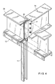
- FIG. 3 is an exemplary illustration of a coupling of the SH panel and the beams (e.g., the peripheral beams and the girder) in correspondence to FIG. 2(C) ;
- FIG. 4 is an illustration of an exemplary structure of the coupling between the SH panel and the peripheral beams shown in FIG. 3 ;
- FIG. 5(A) is an illustration of a first example as to how the SH panel and the beams (the peripheral beams and the girder) are coupled;
- FIG. 5(B) is an illustration of a second example as to how the SH panel and the beams (the peripheral beams and the girder) are coupled;
- FIG. 6 is an illustration of an exemplary structure of the coupling between the SH panel and the peripheral beams shown in FIGS. 5(A) and 5(B) ;
- FIG. 7(A) is an illustration of a first combination of the SH panel and the heavyweight steel frame members with the peripheral beams;
- FIG. 7(B) is an illustration of a second combination of the SH panel and the heavyweight steel frame members with the peripheral beams;
- FIG. 7(C) is an illustration of a third combination of the SH panel and the heavyweight steel frame members with the peripheral beams;
- FIG. 7(D) is an illustration of a fourth combination of the SH panel and the heavyweight steel frame members with the peripheral beams;
- FIG. 7(E) is an illustration of the SH panel of the heavyweight steel frame
- FIG. 7(F) is an illustration of the peripheral beam of the heavyweight steel frame
- FIG. 8 is an illustration of another exemplary embodiment of the present invention (which is embodied in a two-storied building);
- FIG. 9(A) is a sectional view of an exemplary section taken along a line B-B in FIG. 8 ;
- FIG. 9(B) is a plan view of the exemplary section taken along a line B-B in FIG. 8 ;
- FIG. 10(A) is an illustration of an example of the section taken along the line B-B in FIG. 8 ;
- FIG. 10(B) is an illustration of another example of the section taken along the line B-B in FIG. 8 ;
- FIG. 10(C) is an illustration of a beam and a reinforcement member illustrated in FIG. 10(B) ;
- FIG. 11(A) is an illustration of a first example of yet another section taken along the line B-B in FIG. 8 ;
- FIGS. 11(B) and 11(C) are illustrations of second and third examples of yet another section take along the line B-B in FIG. 8 ;
- FIG. 12 illustrates another example (e.g., a two-storied building) according to a further exemplary embodiment of the present invention
- FIG. 13 illustrates a further example (e.g., a two-storied building) according to a further exemplary embodiment of the present invention
- FIG. 14 illustrates a further example (e.g., a two-storied building) according to the a further exemplary embodiment of the present invention
- FIG. 15 illustrates a force resisting walls
- FIG. 16 illustrates a sectional view of a single-storied building constructed by a steel frame work method which is a first prior art method
- FIG. 17 is a front view of the single-storied building shown in FIG. 16 ;
- FIG. 18 is a sectional plan view shown in FIG. 16 ;
- FIG. 19 illustrates a sectional view of a single-storied building constructed by an SH (steel house) method which is a second prior art method
- FIG. 20(A) is front view of a structure as provided in the direction S shown in FIG. 19 , showing an opening of the single-storied building;
- FIG. 20(B) is an illustration of a first example of a portion P of the combination of window lintel shown in FIG. 20(A) ;
- FIG. 20(C) is an illustration of a second example of the portion P of the combination of window lintel shown in FIG. 20(A) ;
- FIG. 20(D) is a front view of a portion T of a lintel bracket shown in FIG. 20(A) ;
- FIG. 20(E) is a side view of the portion T of the lintel bracket shown in FIG. 20(A) ;
- FIG. 21 is an illustration of an SH panel formed of wall frame panels of thin steel sheet coupled to construction surface members
- FIG. 22 is an illustration of a frame construction of a ground floor portion of a steel house
- FIG. 23(A) is an exploded view of a construction of a window frame
- FIG. 23(B) is an illustration of the assembled window frame of FIG. 23(A) ;
- FIG. 24 is an illustration of a low-rise building constructed by a conventional steel house method.
- FIG. 25 is a sectional view taken along a line A-A shown in FIG. 24 .
- FIG. 1 illustrates one example of a single-storied building of a size used for a convenience store or the like, constructed by the steel house (SH) method.
- SH steel house
- a continuous footing 8 and a floor (stall) 2 are formed by placing concrete, and wall frame panels 9 of thin light-gauge section steel are stood on the continuous footing 8 .
- a structure of the wall frame panel 9 can be the same as shown in FIG. 21 ; i.e., the wall frame panel 9 is formed by standing vertical frame members 11 of thin light-gauge section steel on a lower frame member 10 of thin light-gauge section steel, placing an upper frame member 12 of thin light-gauge section steel on the vertical frame members 11 , and fixing a construction surface member 13 to the respective frame members with drill screws 19 .
- This wall frame panel may be called a SH panel 9 a.
- Peripheral beams 5 b of heavyweight steel frame such as heavyweight section steel are provided at the upper end of the SH panel, and girders 5 a of H-shaped steel are bridged between the left and right peripheral beams disposed at a predetermined distance, by which horizontal beams is supported a roof 6 .
- reference numeral denotes 34 a stud for reinforcement.
- a coupling method is important, for smoothly transmitting a force between the wall frame panel 9 of thin steel sheet and the peripheral beam 5 b of heavyweight steel frame.
- a coupling method is important, for smoothly transmitting a force between the wall frame panel 9 of thin steel sheet and the peripheral beam 5 b of heavyweight steel frame.
- an upper frame member 12 of thin steel sheet is disposed downward at the upper ends of the vertical frame members 11 so that the upper ends of the plurality of vertical frames 11 are fixed together.
- Bolts 24 are inserted through holes bored through the contact portions of the respective members and fastened with nuts 25 , whereby the peripheral beam 5 b of the H-shaped steel (heavyweight steel frame) is fastened to the upper end of the SH panel 9 a formed of a construction surface member 13 fixed with the wall frame panel 9 .
- FIG. 2(C) illustrates an example in which a center of the peripheral beam 5 b of the H-shaped steel (that is, a web 26 ) coincides with a thickness center of the SH panel 9 a and both sides of the web 26 are fastened to the SH panel 9 a by the bolts 24 and nuts.
- FIG. 2(B) illustrates another example in which a center of the peripheral beam 5 b of the H-shaped steel (that is, a web 26 ) is shifted from a thickness center of the SH panel 9 a for the reason of design and one side of the web 26 is solely fastened to the SH panel 9 a by the bolt 24 and a nut.
- a center of the peripheral beam 5 b of the H-shaped steel that is, a web 26
- a horizontal additional frame 27 of thin steel sheet channel is arranged above a relatively large opening 15 and fixed at opposite ends thereof to the vertical frame members 11 .
- Vertical additional frames 28 are provided between the horizontal additional frame 27 and the peripheral beam 5 b of the H-shaped steel. These additional frames 27 and 28 have no function for transmitting the vertical load from the upper region of the opening 15 to the vertical members 11 of the SH panel 9 a.
- a coupling plate 30 is welded to a groove section encircled by the upper and lower flanges of the peripheral beam 5 b of the H-shaped steel and the web, and the coupling plate 30 is brought into contact with a lateral side of the web of the H-shaped steel in the girder 5 a .
- Bolts 31 are inserted through holes formed in the contact portion and fastened with nuts, whereby opposite ends of the girder 5 a are fixed to the peripheral beam 5 b.
- FIGS. 5 and 6 illustrate a second exemplary embodiment in which the peripheral beam 5 b of heavyweight steel frame is constructed by a channel. Also in this second exemplary embodiment, a coupling method can smoothly transmit a force between the SH panel 9 a and the peripheral beams 5 b . According to the second exemplary embodiment, this coupling arrangement is formed of a hold-down fastener.
- the upper surface of the web of the upper frame member 12 of thin steel sheet disposed downward at the upper end of the vertical frame member 11 is brought into contact with a lower flange 33 of the peripheral beam 5 b formed of a channel.
- a vertical plate 32 a of the hold-down fastener 32 can be brought into contact with a back surface of the web of the vertical frame member 11 formed of thin steel sheet. Holes may be formed in the contact portion, into which are inserted drill screws 10 to fasten both the members.
- a horizontal plate 32 b provided at the upper end of the hold-down fastener 32 via a reinforcement plate 32 c is positioned in the lower surface of the web of the upper frame member 12 .
- the bolt 24 is inserted into a hole bored upward and downward through the contact portion between the lower flange 33 of the peripheral beam 5 b of channel brought into contact with the upper surface of the web of the upper frame member 12 and the horizontal plate 32 b of the hold-down fastener 32 and fastened to the nut 25 , whereby the peripheral beam 5 b formed of a channel is fixed to the upper end of the SH panel.
- the second exemplary embodiment it is possible to transmit a force between the SH panel 9 a and the peripheral beam 5 b via the hold-down fastener 32 so that a vertical load from the roof 6 or the like is smoothly transmitted to the vertical frame member 11 of the SH panel 9 a , whereby the peripheral beam 5 b is durable against a large withdrawal force applied thereto.
- the peripheral beam 5 b formed of channel may be disposed opposite to FIG. 5(A) as shown in FIG. 5(B) so that the back surface of the web is located outside.
- the first and second exemplary embodiments may also be combined with each other. That is, as an arrangement for coupling the peripheral beam 5 b to the SH panel 9 a , a combination may be used in which the peripheral beam 5 b formed of the H-shaped steel is coupled to the SH panel 9 a by the hold-down fastener 32 and the bolt 24 of the first exemplary embodiment. Also, a combination may be used in which the peripheral beam 5 b formed of the channel is coupled to the SH panel 9 a by the bolt 31 of the second exemplary embodiment.
- FIGS. 7(A) to 7(D) a combination of a peripheral beam (e.g., a girder) 5 b formed of heavy weight steel frame and an SH panel (e.g., a force-resisting wall) 9 a , for the purpose of freely providing an opening 15 , is shown in FIGS. 7(A) to 7(D) .
- a peripheral beam e.g., a girder
- SH panel e.g., a force-resisting wall
- FIG. 7(A) is an example in which the SH panels 9 a are arranged in a well-balanced manner when the width of the opening is not so large and the continuity of a sash is unnecessary.
- FIG. 7(B) is an example in which reinforcement pillars 35 of heavyweight steel frame are provided along the SH panels 9 a disposed at opposite sides of the opening 15 when the stud cannot be disposed midway because a large opening is necessary for a shutter or the like.
- FIG. 7(C) is an example in which a stud 34 of heavyweight steel frame is disposed at a midpoint of the opening 15 when the continuity of a sash is required.
- FIG. 7(D) is an example in which the continuity of a sash is maintained while increasing or decreasing the number of studs 34 of heavyweight steel frame in accordance with the width of the opening.
- a method for coupling the stud 34 of heavyweight steel frame to the peripheral beam 34 of the base is selected from either pinning method or fixing method in view of a balance of the entirety of the building or others.
- FIG. 8 illustrates an exemplary embodiment (e.g., a two-storied building) of the present invention.
- FIGS. 12 , 13 and 14 illustrate other exemplary embodiments of the present invention.
- walls of a ground floor 36 and a second floor 37 are constructed by SH panels (force-resisting wall panels) 9 a , in which the force-resisting wall panels 9 a for the second floor 37 and floor beams 5 d are supported by side beams 5 b and end beams 5 c (both are referred to as beams 5 ) arranged along the upper ends of the force-resisting wall panels 9 a for the ground floor, and a floor panel 2 a can be constructed by bonding a construction surface member (plywood panel) 13 to the floor beams 5 d.
- SH panels force-resisting wall panels
- FIGS. 8 and 12 an opening 15 is provided in a wall vertical to the floor beams 5 d while, in FIG. 13 , the opening 15 is provided in a wall parallel to the floor beams 5 d .
- FIG. 12 illustrates an example of the present invention which has no opening (i.e., referenced as 15 ) in the upper floor, while FIGS. 8 and 13 illustrate other examples having an opening 15 in the upper floor.
- FIG. 14 illustrates an arrangement of the force-resisting wall panels 9 a .
- This force-resisting wall panel 9 a can be structured as shown in FIGS. 15(A) and 15(B) .
- the force-resisting wall panel 9 a is structured by assembling a wall frame member with a lower frame member 10 of thin light-gauge section steel, vertical frame members 11 of thin light-gauge section steel and an upper frame member 12 of thin light-gauge section steel and fixing a construction surface member 13 thereto by drill screws 19 .
- braces 38 are welded or fixed by drill screws 19 to the above-mentioned wall frame member structured by assembling the lower frame member 10 , the vertical frame members 11 and the upper frame member 12 .
- either of the force-resisting wall panel 9 a shown in FIG. 15(A) or 15 (B) may be used.
- the force-resisting wall panel in place of the wall frame member of thin light-gauge section steel, may be constructed by wooden frame members and the surface member (plywood).
- One of the objects of the present invention is to eliminate a conventional lintel in the opening 15 by using the girder 5 a of a special structure in a two or three-storied building constructed by the SH method, in which the coupling structure of three members, the force-resisting wall panel 9 a , the girder 5 a and the floor panel 2 a , constitutes part of the main construction.
- FIGS. 9 to 11 illustrate six examples in which the force-resisting wall panel 9 a , the girder 5 a and the floor panel 2 a are coupled together. These six examples may be classified into three types in accordance with the structure of the girder 5 a , and further into two kinds in accordance with the combination of the three members. Thus, in the drawings, the six examples are shown in total.
- FIG. 9 a first example is illustrated, in which a girder (also called a peripheral beam) 5 a is coupled to three members of a floor panel 2 a .
- FIGS. 10(A) and 10(B) illustrate second and third examples; while FIGS. 11(A) , 11 (B) and 11 (C) illustrate fourth, fifth and sixth examples, respectively.
- a coupling structure is illustrated, in which vertical and horizontal forces applied to the opening 15 formed in the wall are relatively small, for example, when the opening 15 is disposed on the wall surface parallel to the floor beam 5 d .
- coupling structures are illustrated, in which vertical and horizontal forces applied to the opening 15 formed in the wall are relatively large, for example, when the opening is disposed on the wall surface vertical to the floor beam 5 d.
- the girder 5 a is constructed of: (i) a channel steel in FIGS. 9 and 11(A) , (ii) an H-shaped steel in FIGS. 10(A) and 11(B) ; and (iii) a combination member, in which two thin light-gauge channels are coupled in a back-to-back relationship, in FIGS. 10(B) and 11(C) .
- the floor beam 5 d is coupled to the lateral side of the girder 5 a by bolts.
- the floor beam 5 d is placed on the upper surface of the girder 5 a and coupled by bolts.
- FIGS. 9 to 11 Detailed structures shown in FIGS. 9 to 11 are described as follows.
- a lower flange 21 of a circumferential girder 5 formed of a channel which is disposed so that the web 26 is vertical and the channel portion that is outward is brought into contact with the upper surface of the web of an upper frame member 12 formed of thin light-gauge channel in a force-resisting wall panel 9 a , and a bracing plate 39 is disposed on the lower surface of the web.
- a bracket 20 provided at an end of the floor beam 5 d is brought into contact with a back surface of the web in the circumferential beam 5 formed of channel steel.
- This bracket 20 is formed of a lipped channel of thin steel sheet cut into short pieces and is coupled to an end of the floor beam 5 d in the vertical posture so that one flange thereof is brought into contact with a back surface of the web in the girder 5 a .
- a bolt 24 is inserted through the contact portion via a bracing plate 39 and screw-engaged with a nut 25 .
- the floor beam 5 d is coupled to the girder 5 a .
- a reinforcement member 40 is provided in the channel portion of the girder 5 a .
- the floor panel 2 a is structured by the floor beams 5 d on which the construction surface member 13 is bonded.
- the lower frame member 1 of thin light-gauge channel in the force-resisting wall panel 7 in the upper floor is placed and fixed by bolts.
- a bolt 24 is inserted into a hole bored through these members and fastened to a nut 25 to couple the force-resisting wall panel 9 a to the girder 5 a .
- the bracket 20 provided at the end of the floor beam 5 d is brought into contact with a back surface of the web of the girder 5 a formed of H-shaped steel.
- the remaining structure is the same as the first example shown in FIG. 9 .
- the girder 5 a is constructed by a combination of two members formed of thin light-gauge channel steel coupled so that the back surfaces thereof are opposed to each other.
- the lower flange 21 of the girder 5 a disposed so that the web 26 thereof extends in the vertical direction, is brought into contact with the upper surface of the web of the upper frame member 12 formed of thin light-gauge channel steel in the force-resisting wall panel 9 a , and the respective members in the contact portion are coupled to each other by bolts or drill screws, whereby the force-resisting wall panel 9 a is coupled to the girder 5 a .
- the reinforcement member 40 is provided in the channel of the girder 5 a formed of the combination of the thin light-gauge channel steel members.
- the remaining structure is the same as the first example shown in FIG. 9 .
- the girder 5 a functions as an lintel in the prior art without any problems.
- the vertical force and the horizontal force supported by the girder 5 a provided in the wall having the opening 15 parallel to the floor beam 5 d are relatively small in comparison with the vertical arrangement, it is possible to ensure a sufficient supporting force even if the end of the floor beam 5 d is coupled to the lateral side of the girder 5 a.
- FIGS. 11(A) , 11 (B) and 11 (C) illustrate fourth, fifth and sixth examples, respectively, in which the girder 5 a on the force-resisting wall panel 9 a is coupled to the floor beam 5 d on the wall surface having the opening disposed vertical to the floor beam 5 d .
- the end of the floor beam 5 d is placed on the girder 5 a and coupled thereto by bolts.
- the girder 5 a shown in FIGS. 11(A) , 11 (B) and 11 (C) has the same structure as the girder 5 a shown in FIGS. 9 , 10 (A) and 10 (B). Also, the coupling structure thereof with the upper end of the force-resisting wall panel 9 a may be the same as that shown in the above-identified figures.
- the floor beam 5 d has the same structure as the floor beam 5 d shown in FIGS. 9 , 10 (A) and 10 (B).
- the end beam 5 c formed of thin light-gauge channel steel and coupled with the floor beam 5 d is placed on the upper surface of the upper flange 41 of the girder 5 a formed of channel steel.
- the bolt 24 is provided through the coupling portion of the upper flange 41 , the thin light-gauge channel steel member and the bracing plate 39 and fastened to the nut 25 , whereby the girder 5 a is coupled to the floor beam 5 d .
- the lower frame member 10 formed of thin light-gauge channel steel in the force-resisting wall panel 9 a in the upper floor is placed and fastened by bolts.
- the end beam 5 c formed of thin light-gauge channel steel and coupled with the floor beam 5 d is placed on the upper surface of the upper flange 41 of the girder 5 a formed of channel steel.
- the bolt 24 is provided through the coupling portion of the upper flange 41 , the thin light-gauge channel steel member and the bracing plate 39 and fastened to the nut 25 , whereby the girder 5 a is coupled to the floor beam 5 d.
- the lower frame member 10 formed of thin light-gauge channel steel in the force-resisting wall panel 9 a in the upper floor is placed and fastened by bolts.
- the end beam 5 c formed of thin light-gauge channel steel and coupled with the floor beam 5 d is placed on the upper surface of the upper flange 41 of the girder 5 a formed of the combined members of thin light-gauge channel steel.
- the bolt 24 is provided through the coupling portion of the upper flange 41 , the thin light-gauge channel steel member and the bracing plate 39 and fastened to the nut 25 , whereby the girder 5 a is coupled to the floor beam 5 d.
- a reinforcement frame 42 formed of thin light-gauge channel steel is provided on the outside surface of the end beam 5 c , and the lower frame member 10 formed of thin light-gauge channel steel in the force-resisting wall panel 9 a in the upper floor is placed on the upper surface of the end of the construction surface member 13 bonded to the upper surface of the floor beam 5 d and coupled by bolts.
- the girder 5 a high in rigidity and formed of heavyweight channel steel or H-shaped steel or the combined member of thin light-gauge channel steel, may be provided on the wall surface having the opening 15 (see FIG. 14 ), the girder 5 a can function as an lintel in the prior art without any problems.
- the structure of the respective portion and the fastening member may be suitably changed in accordance with loads applied to the girder, which changes in design should be understood by those of ordinary skill in the art as being completely disclosed by the description and drawings referenced herein.
- the advantages of the steel house method in the construction of a low-rise building mainly using frame members formed of thin light-gauge section steel in that no welding is necessary, the cutting and boring are simple, the material is light in weight and capable of being manually conveyed, the panel accuracy may be improved and/or ensured, the execution of work can be easier, the construction period may be short and the manufacturing cost may be low, the problems thereof, in that the strength is too weak to support a roof load, are solved by combining the members of thin light-gauge section steel with a horizontal beam member of heavyweight section steel, high in strength, which is simple in structure because the roof truss is unnecessary.
- the circumferential beam on the force-resisting wall panel is formed of heavyweight section steel such as an H-shaped steel or a channel or the combination beam of thin light-gauge section steel, it is possible to omit the lintel member and thus to enlarge the height and width of the opening, while maintaining the merits of the conventional SH technology in that the roof and the floor panels are efficiently manufactured in a factory and the site work may be simplified.
Landscapes
- Engineering & Computer Science (AREA)
- Architecture (AREA)
- Physics & Mathematics (AREA)
- Electromagnetism (AREA)
- Civil Engineering (AREA)
- Structural Engineering (AREA)
- Load-Bearing And Curtain Walls (AREA)
- Panels For Use In Building Construction (AREA)
Abstract
A frame construction for a low rise building. In the construction, a wall frame panel is made of thin light-gauge section steel by bonding together a surface member, a lower frame member, vertical frame members and an upper frame member. Roof or floor support girders are made of heavyweight section steel having H-shape or channel shape. The girders are coupled to frame construction panels by bolts or hold-down fasteners.
Description
This application is a continuation application of Ser. No. 11/255,246 filed Oct. 21, 2005 now abandoned which is a divisional of U.S. patent application Ser. No. 10/495,406 filed May 12, 2004 now abandoned as a national phase application of International patent application No. PCT/JP02/04966 filed on May 22, 2002 (published as WO 03/031669) claiming priority to Japanese patent application Nos. JP 2001347119 and JP 2001348879 that were filed on Nov. 13, 2001 and Nov. 14, 2001, respectively. This application claims the benefit under 35 U.S.C. §119 and §235 of all of the aforementioned applications, all of which applications are incorporated by reference herein in their entireties.
The present invention relates to a frame construction for a low-rise building of one to three stories having a large opening such as a doorway or a window, and/or for a large span low-rise building of, e.g., one to three stories having a large opening such as a doorway or a window.
While a steel frame work method (hereinafter referred to as a first prior art method) has been mainly employed as a construction method for a low-rise building of one to three stories in the prior art, a steel house construction method has recently been prevalent. In this regard, the steel house is defined as a building of a steel panel structure composed of frame members made of thin lightweight section steel and construction surface members or braces. This construction method is referred to as a second prior art method hereinafter.
An example of a single-storied building constructed by the first prior art method (the steel frame work method) is illustrated in FIGS. 16 to 18 . Individual footings 1 and a floor (a stall) 2 are constructed from concrete.
The features of the first example are as follows. A material cost for the roof is low; the number of parts is low; manufacturing is easy; site work is easy in that one day is sufficient for erecting a building for a convenience store or the like; the opening is freely prepared (if necessary, studs may be used in accordance with a width of the opening); and only cutting of the constituent members is needed. However, drawbacks thereof are that the precision of execution of work is liable to vary; LGS (light-gage steel) is necessary as a substrate for finishing the wall; and site work needs two days.
As shown in FIG. 21 , the wall frame panel 9 is formed by standing vertical frame members 11 of thin light-gauge section steel on a lower frame member 10 of thin light-gauge section steel, placing an upper frame member 12 of thin light-gauge section steel on the vertical frame members 11, and fixing a construction surface member 13 to the respective frame members with drill screws 19. Hereinafter, the product obtained by fixing the construction surface member 13 to the respective frame members is referred to as an SH panel 9.
Further, a truss 14 of thin light-gauge section steel (hereinafter referred to as an SH truss) is assembled to be supported by the wall frame panel 9, and a roof 6 is supported by the SH truss 14. In FIG. 20(A) , reference numeral 15 denotes a relatively large opening (e.g., a window or a doorway).
As shown in FIG. 20(A) , both ends of a lintel 16 are fixed to the vertical frame members 11 via lintel brackets 17 above the opening 15 for transmitting a vertical load from the roof to the wall frame panel 9. FIGS. 20(B) and 20(C) illustrate examples of the lintel 16, in which lipped channels 16 a of thin steel sheet are opposed to each other and the outside thereof is reinforced with a reinforcement channel(s) 18.
In such a manner, the steel house is constructed by using the frame members of thin light-gauge section steel as main frame elements, to which wood frame members are partially combined or a surface member of plywood is used as a construction surface member if necessary.
The frame member of thin light-gauge section steel is formed by shaping a thin steel sheet of approximately 1 mm thick, through roll-forming, to be a channel, a lipped channel or a box so that a width or others thereof is matched with a predetermined specification.
A further example of a frame construction according to the second prior art method is illustrated in FIGS. 22 to 25 . A plurality of vertical frame members 11 are provided from lower frame members 10 at a distance between the adjacent ones thereof, and the upper ends of the respective vertical frame members 11 are coupled by upper frame members 12.
Wall frame panels (force-resisting wall panels) 9 are formed by attaching construction surface members 13 (see FIGS. 24 and 25 ) or braces to the wall frame members constructed by the lower frame members 10, the vertical frame members 11 and the upper frame members 12. Openings 15 such as a doorway 7 or a window 7 a are formed in the building.
Opposite ends of the longer beam 5 d are coupled to the front and rear end beams 5 c via brackets 20, while one end of the shorter beam 5 d is coupled to the front or rear end beam 5 c and the other end thereof is coupled to a girder 5 a via brackets 11, respectively.
One end of the girder 5 a is coupled to the side beam 5 b, while the other end thereof is coupled to the longer beam 5 d via the brackets 20, respectively. A floor panel 2 is constructed by covering the beams 5 d with the construction surface members 13 of plywood or the like.
In FIG. 22 , reference numeral 5 e denotes an end beam in the floor opening, 5 f denotes a side beam in the opening, 20 a denotes a beam bracket, and 20 b denotes a cleat.
In the above-mentioned building according to the SH method, as there are no vertical frame members 11 in the opening 15 such as a doorway 7 or a window 7 a, no columns exist in the opening 15, for supporting a vertical load from the upper portion of the building such as a roof, resulting in the deterioration of strength in the opening 15.
Therefore, it may be necessary to reinforce the upper portion above the opening 15. Thus, the lintel 16 is provided above the opening 15.
As shown in FIG. 22 , an upper frame member 12 and a lintel frame member 16 b are provided above and beneath the lintel 16 of the window 7 a, respectively.
The bracket 20 is formed by cutting a lipped channel of thin light-gauge section steel into short pieces and disposing it so that the channel portion is in the vertical direction. The lintel 16 arranged beneath the end beam 5 c and coupled thereto by drill screws is formed by opposing the lipped thin light-gauge channels 16 a to each other and fixing the upper and lower sides thereof by connection frame members 16 d.
According to the second prior art method (the steel house (SH) method), a skeleton is constructed of the force-resisting wall panels (SH panels) constructed by the wall frame members which are formed by assembling the frame members of thin light-gauge section steel by using the drill screws and are coupled to the construction surface members also by using the drill screws. The merit thereof is that the thin light-gauge section steel necessitates no welding, and is easily cut and drilled, as well as it also being light in weight and capable of being manually conveyed, whereby the working efficiency is high and the manufacturing cost is low.
The merit of the force-resisting wall panel (SH panel) is that the accuracy of the product is stable and prefabrication of the panel is possible, whereby the execution of work becomes easy due to the shortening of construction period and the maintenance of panel accuracy.
For example, in a single-storied building for a convenience store, the period of erection is half of a day, and in a two or three storied building of approximately 99 to 132 m2, the period of erection is two days. Accordingly, this construction method is economical in the field of low-rise buildings.
The second prior art method (steel house (SH) method), however, has the following drawbacks. For example, in the building for a convenience store or the like, it is required that a large opening is formed on the wall surface and the number of columns is reduced to as small as possible to ensure a large space.
That is, in the building, when a roof of large span is constructed in correspondence to a required large span of several meters or longer, as the cross-section of the thin light-gauge section steel is small, the strength thereof is too weak to support a load from the roof solely by the end members. Thereby, it is necessary to construct a roof truss consisting of a plurality of members.
In the above-mentioned roof truss, the number of parts increases, the number of portions to be coupled by drill screws or bolts increases, and an area of the side surface wall increases, which are uneconomical because of the increase in man-hours. Also, when it is required to guarantee a large room space, the second prior art method could not respond to a case in which the span between supports of the roof is as large as ten or more meters.
In the low-rise building of 2 to 3 stories constructed by thin light-gauge section steel, as an opening such as a doorway or a window formed on the wall surface lacks the strength for supporting the vertical load applied from above, the lintel is provided in the upper portion of the opening to distribute the vertical load, applied to the opening from above, to the opposite vertical frames of the force-resisting wall panel.
The lintel is required to have a strength capable of withstanding a vertical load, from above, such as the load of a roof or a floor. Thereby, the lintel preferably uses a member in which a plurality of thin light-gauge section steel pieces are combined to result in the complexity of the manufacture and construction of the lintel.
Further, when the opposite ends of the lintel are attached to the side ends of the force-resisting wall panel disposed on both sides of the opening, the attachment of the lintel to the peripheral members becomes complex in relation to complexity in the structure of the lintel. Further, the height of the opening (i.e., reference h provided in FIG. 24 ) can be restricted due to the existence of the lintel.
One of the objects of the present invention is to provide a frame construction for a low-rise building in which the above-mentioned problem has been solved. For example, such frame construction may be preferably free from the drawbacks of the SH method while maintaining the advantages of a steel house for a low-rise building (for example, a single or two to three-storied building for a convenience store), which partially adopts a heavyweight steel frame structure (hereinafter referred to as a mixed construction) or a frame member construction consisting of a plurality of thin light-gauge section steels coupled together (hereinafter referred to as a composite construction).
Further, another object of the present invention is to provide frame construction which maintains the advantage of the frame members of thin light-gauge section steel used in the SH method in that it is light in weight and capable of being manually conveyed; and eliminating the drawback thereof in that it is inferior in strength, by combining the same with heavyweight section steel which is inferior in execution property and heavy in weight.
Thus, the frame construction for the low-rise building is provided, having features of both the frame member made of thin light-gauge section steel and the heavyweight section steel.
For example, in the low-rise building, the lintel is generally not used in the opening, but the force-resisting wall panel and the roof panel or the floor panel can be coupled together via the girder provided in the upper portion of the force-resisting wall panel. As a result, a frame construction is provided, which require no time for processing the lintel and is free from a restriction in the height of the opening.
According to one exemplary embodiment of the present invention, a frame construction for a low-rise building is provided. In particular, a wall frame panel structured from a lower frame member, an upper frame member and vertical frame members of thin light-gauge section steel is coupled to a girder of heavyweight steel provided at the upper end of the wall frame panel by a coupling arrangement comprising bolts and/or hold-down fasteners. A reinforcement steek column may also be provide.
The wall frame panel can be structured by fixing a construction surface member or a brace to the lower frame member, the upper frame member and the vertical frame members. The girder may be formed of channel steel, and the channel steel can be coupled to the upper frame member of the wall frame panel by bolts. The girder may also be formed of H-shaped steel, and the H-shaped steel is coupled to the upper frame member of the wall frame panel by bolts. For example, the channel steel may be coupled to the upper frame member of the wall frame panel by bolts via a hold down fastener disposed s that a horizontal member is on the upper side, and/or the H-shaped steel can be coupled to the upper fram member of the wall fram panel by bolts via a hold-down fastener disposed so that a horizontal member is on the upper side.
According to yet a further embodiment of the present invention, in the low-rise building constructed by the SH method using frame members of thin light-gauge channel steel, the problem of the thin light-gauge section steel, that it is weak in mechanical strength and inferior in processibility, may be solved by combining the same with heavyweight section steel, while maintaining the merit thereof in that it is light in weight and capable of being manually conveyed, it is possible to smoothly support a roof load by a simple construction based on the steel house method without using a complicated structure such as a roof truss or others.
It may be advantageous to have a large opening present on the wall surface and a large space is obtained in the building by decreasing the number of columns as much as possible. For this purpose, a large span of several meters or more is required. According to still another exemplary embodiment of the present invention, a building such as a convenience store which may need such a large span can be reasonably constructed. Indeed, the exemplary embodiments of the present invention may solve the following problem which may be inherent to the steel house method: e.g., (i) a cost for constructing a roof is high because it may be necessary to form a truss in the roof portion because the cross-section of the frame member of thin light-gauge channel is thin, resulting in the inferior strength, and the frame member of thin light-gauge section steel is unsuitable for a structure for supporting the roof by a large span of ten or more meters or more when a large room space may be desired.
Also, the coupling method can be useful for smoothly transmitting a force between the horizontal member of heavyweight steel frame for supporting the roof and the assembled panel of thin steel frames.
According to yet another exemplary embodiment of the present invention, a force may be transmitted as an axial force to vertical frame members of the assembled panel of thin steel frames, whereby the arrangement can be durable against a large withdrawing force.
For example, the frame construction can include a wall frame panel formed of frame members of thin light-gauge section steel and attached to a construction surface member or a brace, and a girder that is provided above the wall frame panel for supporting a floor panel or a roof. The girder may be formed of section steel and coupled to the force-resisting panel and/or the floor panel by bolts, and a lintel is not needed above the opening so that the opening extends to directly beneath the girder. In addition, a reinforcement member can be provided in a channel of the girder formed of section steel.
According to a further exemplary embodiment of the present invention, the frame construction having an opening in a wall thereof includes a wall frame panel (formed of frame members of thin light-gauge section steel) attached to a construction surface member or a brace, as well as a girder provided above the wall frame panel for supporting a floor panel or a roof. In this exemplary embodiment, the frame construction can be formed from a plurality of thin light-gauge section steel members assembled together and coupled to the force-resisting panel and/or the floor panel by bolts, and the lintel does not have to be provided above the opening so that the opening extends to directly beneath the girder. In addition a reinforcement member can be provided in a channel of the girder formed of the assembled members.
According to another exemplary variant of the present invention the girder, provided on the wall surface having the opening extending parallel to beams, can be formed of a channel steel disposed so that the web thereof extends in the vertical direction, and a lateral side of the beam is brought into contact with a back surface of the web of the channel steel and coupled to the latter by bolts.
In another variant of the present invention, the girder, provided on the wall surface having the opening extending parallel to beams, can be formed of an H-shaped steel disposed so that the web thereof extends in the vertical direction, and a lateral side of the beam is brought into contact with a web surface of the H-shaped steel and coupled to the latter by bolts. According to yet another variant of the present invention, the girder, provided on the wall surface having the opening extending vertical to beams, may be formed of a channel steel disposed so that the web thereof extends in the vertical direction, and an end of the beam is placed on the upper surface of the upper flange of the channel steel and coupled to the latter by bolts.
Further, the girder, provided on the wall surface having the opening extending vertical to beams, can be formed of a H-shaped steel disposed so that the web thereof extends in the vertical direction, and an end of the beam is placed on the upper surface of the upper flange of the H-shaped steel and coupled to the latter by bolts. The assembled members of thin light-gauge section steel constituting the girder, provided on the wall surface having the opening extending parallel to beams, may be disposed so that the web thereof extends in the vertical direction, and a lateral side of the beam is brought into contact with the inner surface of the web and coupled to the latter by bolts.
Alternatively, the assembled members of thin light-gauge section steel constituting the girder, provided on the wall surface having the opening extending vertical to beams, can be disposed so that the web thereof extends in the vertical direction, and an end of the beam is brought into contact with the upper surface of the upper surface of the respective upper flange of the assembled member and coupled to the latter by bolts.
According to a still further exemplary embodiment of the present invention, by constituting the girder disposed above the force-resisting wall panel with heavyweight steel such as H-shaped steel or channel steel, or the assembled members of thin light-gauge channel steel, it is possible to eliminate the lintel in the low-rise building, whereby it is possible to enlarge the height and width of the opening due to the elimination of lintel, while maintaining the advantage of the method for constructing the steel house mainly formed of frame members of thin light-gauge section steel in that no welding is necessary, cutting and boring are simple, the working efficiency is high, because the material is light in weight and can be manually conveyed, the force-resisting wall panel, the roof and the floor panel are efficiently manufactured in the factory at a high accuracy, the site work is simplified, the construction period is short, and the manufacturing cost is low.
Exemplary embodiments of the present invention will be described with reference to the attached drawings, in which the same reference numerals are used for denoting the same elements.
A first exemplary embodiment of the present invention is illustrated in FIGS. 1 to 4 . FIG. 1 illustrates one example of a single-storied building of a size used for a convenience store or the like, constructed by the steel house (SH) method.
A continuous footing 8 and a floor (stall) 2 are formed by placing concrete, and wall frame panels 9 of thin light-gauge section steel are stood on the continuous footing 8. A structure of the wall frame panel 9 can be the same as shown in FIG. 21 ; i.e., the wall frame panel 9 is formed by standing vertical frame members 11 of thin light-gauge section steel on a lower frame member 10 of thin light-gauge section steel, placing an upper frame member 12 of thin light-gauge section steel on the vertical frame members 11, and fixing a construction surface member 13 to the respective frame members with drill screws 19. This wall frame panel may be called a SH panel 9 a.
In the above structure, a coupling method is important, for smoothly transmitting a force between the wall frame panel 9 of thin steel sheet and the peripheral beam 5 b of heavyweight steel frame. Provided below is an explanation thereof.
According to a first exemplary embodiment of the present invention in which the peripheral beam 5 b is formed of H-shaped steel, as shown in FIGS. 2 and 3 , an upper frame member 12 of thin steel sheet is disposed downward at the upper ends of the vertical frame members 11 so that the upper ends of the plurality of vertical frames 11 are fixed together.
Further, the lower surface of a lower flange 21 of the peripheral beam 5 b of H-shaped steel is brought into contact with the upper surface of a web of the upper frame member 12, and a reinforcement plate 23 of a predetermined thickness is brought into contact with the lower surface of the web of the upper frame member 12.
For example, in FIG. 2(A) , a horizontal additional frame 27 of thin steel sheet channel is arranged above a relatively large opening 15 and fixed at opposite ends thereof to the vertical frame members 11. Vertical additional frames 28 are provided between the horizontal additional frame 27 and the peripheral beam 5 b of the H-shaped steel. These additional frames 27 and 28 have no function for transmitting the vertical load from the upper region of the opening 15 to the vertical members 11 of the SH panel 9 a.
When the SH panel is coupled to the beams as shown in FIGS. 3 and 4 , as an arrangement for coupling the left and right peripheral beams 5 b provided at the upper end of the SH panel 13 to the girder 5 a of the H-shaped steel bridged between the two, a coupling plate 30 is welded to a groove section encircled by the upper and lower flanges of the peripheral beam 5 b of the H-shaped steel and the web, and the coupling plate 30 is brought into contact with a lateral side of the web of the H-shaped steel in the girder 5 a. Bolts 31 are inserted through holes formed in the contact portion and fastened with nuts, whereby opposite ends of the girder 5 a are fixed to the peripheral beam 5 b.
According to the above coupling structure, it is possible to smoothly transmit the vertical load from the roof 6 or the like to the vertical frame members 11 of the SH panel 9 a as well as to endure a large withdrawing force applied to the peripheral beam 5 b.
In order to connect the upper ends of a plurality of vertical frame members 11, the upper surface of the web of the upper frame member 12 of thin steel sheet disposed downward at the upper end of the vertical frame member 11 is brought into contact with a lower flange 33 of the peripheral beam 5 b formed of a channel.
On the other hand, a vertical plate 32 a of the hold-down fastener 32 can be brought into contact with a back surface of the web of the vertical frame member 11 formed of thin steel sheet. Holes may be formed in the contact portion, into which are inserted drill screws 10 to fasten both the members.
At this time, a horizontal plate 32 b provided at the upper end of the hold-down fastener 32 via a reinforcement plate 32 c is positioned in the lower surface of the web of the upper frame member 12.
The bolt 24 is inserted into a hole bored upward and downward through the contact portion between the lower flange 33 of the peripheral beam 5 b of channel brought into contact with the upper surface of the web of the upper frame member 12 and the horizontal plate 32 b of the hold-down fastener 32 and fastened to the nut 25, whereby the peripheral beam 5 b formed of a channel is fixed to the upper end of the SH panel.
Also, in the second exemplary embodiment, it is possible to transmit a force between the SH panel 9 a and the peripheral beam 5 b via the hold-down fastener 32 so that a vertical load from the roof 6 or the like is smoothly transmitted to the vertical frame member 11 of the SH panel 9 a, whereby the peripheral beam 5 b is durable against a large withdrawal force applied thereto.
The rest of the construction may be the same as that of the first exemplary embodiment. In this regard, as a modification of the second exemplary embodiment, the peripheral beam 5 b formed of channel may be disposed opposite to FIG. 5(A) as shown in FIG. 5(B) so that the back surface of the web is located outside.
The first and second exemplary embodiments may also be combined with each other. That is, as an arrangement for coupling the peripheral beam 5 b to the SH panel 9 a, a combination may be used in which the peripheral beam 5 b formed of the H-shaped steel is coupled to the SH panel 9 a by the hold-down fastener 32 and the bolt 24 of the first exemplary embodiment. Also, a combination may be used in which the peripheral beam 5 b formed of the channel is coupled to the SH panel 9 a by the bolt 31 of the second exemplary embodiment.
Next, a combination of a peripheral beam (e.g., a girder) 5 b formed of heavy weight steel frame and an SH panel (e.g., a force-resisting wall) 9 a, for the purpose of freely providing an opening 15, is shown in FIGS. 7(A) to 7(D) .
In this regard, it may be preferable to employ a method for coupling the stud 34 of heavyweight steel frame to the peripheral beam 34 of the base is selected from either pinning method or fixing method in view of a balance of the entirety of the building or others.
According to the exemplary embodiments of the present invention (e.g., buildings) shown in FIGS. 8 and 12-14, walls of a ground floor 36 and a second floor 37 are constructed by SH panels (force-resisting wall panels) 9 a, in which the force-resisting wall panels 9 a for the second floor 37 and floor beams 5 d are supported by side beams 5 b and end beams 5 c (both are referred to as beams 5) arranged along the upper ends of the force-resisting wall panels 9 a for the ground floor, and a floor panel 2 a can be constructed by bonding a construction surface member (plywood panel) 13 to the floor beams 5 d.
In FIGS. 8 and 12 , an opening 15 is provided in a wall vertical to the floor beams 5 d while, in FIG. 13 , the opening 15 is provided in a wall parallel to the floor beams 5 d. Further, FIG. 12 illustrates an example of the present invention which has no opening (i.e., referenced as 15) in the upper floor, while FIGS. 8 and 13 illustrate other examples having an opening 15 in the upper floor.
In the example shown in FIG. 15(A) , the force-resisting wall panel 9 a is structured by assembling a wall frame member with a lower frame member 10 of thin light-gauge section steel, vertical frame members 11 of thin light-gauge section steel and an upper frame member 12 of thin light-gauge section steel and fixing a construction surface member 13 thereto by drill screws 19.
In the example of the force-resisting wall panel 9 a shown in FIG. 15(B) , braces 38 are welded or fixed by drill screws 19 to the above-mentioned wall frame member structured by assembling the lower frame member 10, the vertical frame members 11 and the upper frame member 12.
According to another exemplary embodiment of the present invention, either of the force-resisting wall panel 9 a shown in FIG. 15(A) or 15(B) may be used. In this regard, in place of the wall frame member of thin light-gauge section steel, the force-resisting wall panel may be constructed by wooden frame members and the surface member (plywood).
One of the objects of the present invention is to eliminate a conventional lintel in the opening 15 by using the girder 5 a of a special structure in a two or three-storied building constructed by the SH method, in which the coupling structure of three members, the force-resisting wall panel 9 a, the girder 5 a and the floor panel 2 a, constitutes part of the main construction.
In FIG. 9 , a first example is illustrated, in which a girder (also called a peripheral beam) 5 a is coupled to three members of a floor panel 2 a. FIGS. 10(A) and 10(B) illustrate second and third examples; while FIGS. 11(A) , 11(B) and 11(C) illustrate fourth, fifth and sixth examples, respectively.
In the third example (see FIG. 3(B)), a coupling structure is illustrated, in which vertical and horizontal forces applied to the opening 15 formed in the wall are relatively small, for example, when the opening 15 is disposed on the wall surface parallel to the floor beam 5 d. In the first, second and fourth to sixth examples, coupling structures are illustrated, in which vertical and horizontal forces applied to the opening 15 formed in the wall are relatively large, for example, when the opening is disposed on the wall surface vertical to the floor beam 5 d.
Constituent elements common to the first to sixth examples will be explained with reference to FIGS. 9 to 11 .
The girder 5 a is constructed of: (i) a channel steel in FIGS. 9 and 11(A) , (ii) an H-shaped steel in FIGS. 10(A) and 11(B) ; and (iii) a combination member, in which two thin light-gauge channels are coupled in a back-to-back relationship, in FIGS. 10(B) and 11(C) . In the girder 5 a provided on the wall surface having the opening 15 parallel to the floor beam 5 d, as shown in FIGS. 9 , 10(A) and 10(B), the floor beam 5 d is coupled to the lateral side of the girder 5 a by bolts.
In the girder 5 a provided on the wall surface having the opening 15 vertical to the floor beam 5 d, as shown in FIGS. 11(A) , 11(B) and 11(C), the floor beam 5 d is placed on the upper surface of the girder 5 a and coupled by bolts.
Detailed structures shown in FIGS. 9 to 11 are described as follows.
In the first example shown in FIG. 9 , at the upper end of a force-resisting wall panel 9 a, a lower flange 21 of a circumferential girder 5 formed of a channel which is disposed so that the web 26 is vertical and the channel portion that is outward is brought into contact with the upper surface of the web of an upper frame member 12 formed of thin light-gauge channel in a force-resisting wall panel 9 a, and a bracing plate 39 is disposed on the lower surface of the web.
Through the respective members in the coupling portion, bolts 24 are provided and screw-engaged with nuts 25. Thus, the force-resisting wall panel 9 a is coupled to the girder 5 a.
A bracket 20 provided at an end of the floor beam 5 d is brought into contact with a back surface of the web in the circumferential beam 5 formed of channel steel. This bracket 20 is formed of a lipped channel of thin steel sheet cut into short pieces and is coupled to an end of the floor beam 5 d in the vertical posture so that one flange thereof is brought into contact with a back surface of the web in the girder 5 a. A bolt 24 is inserted through the contact portion via a bracing plate 39 and screw-engaged with a nut 25.
Thus the floor beam 5 d is coupled to the girder 5 a. In the channel portion of the girder 5 a, a reinforcement member 40 is provided.
As described before, the floor panel 2 a is structured by the floor beams 5 d on which the construction surface member 13 is bonded. On the upper flange 41 of the girder 5 a, the lower frame member 1 of thin light-gauge channel in the force-resisting wall panel 7 in the upper floor is placed and fixed by bolts.
Next, in the second example shown in FIG. 10(A) , at the upper end of the force-resisting wall panel 9 a, a lower flange 21 of the girder 5 a formed of H-shaped steel, disposed so that the web 26 thereof extends in the vertical direction, is brought into contact with the upper surface of a web of the upper frame member 12, and the bracing plate 39 is provided on the lower surface of the web.
A bolt 24 is inserted into a hole bored through these members and fastened to a nut 25 to couple the force-resisting wall panel 9 a to the girder 5 a. The bracket 20 provided at the end of the floor beam 5 d is brought into contact with a back surface of the web of the girder 5 a formed of H-shaped steel. The remaining structure is the same as the first example shown in FIG. 9 .
In the third example shown in FIG. 10(B) , the girder 5 a is constructed by a combination of two members formed of thin light-gauge channel steel coupled so that the back surfaces thereof are opposed to each other.
The lower flange 21 of the girder 5 a, disposed so that the web 26 thereof extends in the vertical direction, is brought into contact with the upper surface of the web of the upper frame member 12 formed of thin light-gauge channel steel in the force-resisting wall panel 9 a, and the respective members in the contact portion are coupled to each other by bolts or drill screws, whereby the force-resisting wall panel 9 a is coupled to the girder 5 a. In the channel of the girder 5 a formed of the combination of the thin light-gauge channel steel members, the reinforcement member 40 is provided. The remaining structure is the same as the first example shown in FIG. 9 .
In the first to third examples, as the girder 5 a high in rigidity formed of heavyweight steel such as channel or H-shaped steel or the combined member of thin light-gauge channel steel is provided above the force-resisting wall panel 9 a on the wall surface having the opening 15 (see FIG. 1 ), the girder 5 a functions as an lintel in the prior art without any problems.
Thus, even if the lintel is omitted from the opening in the conventional steel house construction method, it is possible to sufficiently support the vertical load from the upper floor or the horizontal force.
Also, as the vertical force and the horizontal force supported by the girder 5 a provided in the wall having the opening 15 parallel to the floor beam 5 d are relatively small in comparison with the vertical arrangement, it is possible to ensure a sufficient supporting force even if the end of the floor beam 5 d is coupled to the lateral side of the girder 5 a.
The girder 5 a shown in FIGS. 11(A) , 11(B) and 11(C) has the same structure as the girder 5 a shown in FIGS. 9 , 10(A) and 10(B). Also, the coupling structure thereof with the upper end of the force-resisting wall panel 9 a may be the same as that shown in the above-identified figures. The floor beam 5 d has the same structure as the floor beam 5 d shown in FIGS. 9 , 10(A) and 10(B).
As shown in FIG. 11(A) , the end beam 5 c formed of thin light-gauge channel steel and coupled with the floor beam 5 d is placed on the upper surface of the upper flange 41 of the girder 5 a formed of channel steel.
The bolt 24 is provided through the coupling portion of the upper flange 41, the thin light-gauge channel steel member and the bracing plate 39 and fastened to the nut 25, whereby the girder 5 a is coupled to the floor beam 5 d. On the upper surface of the end of the construction surface member 13 bonded to the upper surface of the floor beam 5 d, the lower frame member 10 formed of thin light-gauge channel steel in the force-resisting wall panel 9 a in the upper floor is placed and fastened by bolts.
As shown in FIG. 11(B) , the end beam 5 c formed of thin light-gauge channel steel and coupled with the floor beam 5 d is placed on the upper surface of the upper flange 41 of the girder 5 a formed of channel steel. The bolt 24 is provided through the coupling portion of the upper flange 41, the thin light-gauge channel steel member and the bracing plate 39 and fastened to the nut 25, whereby the girder 5 a is coupled to the floor beam 5 d.
On the upper surface of the end of the construction surface member 13 bonded to the upper surface of the floor beam 5 d, the lower frame member 10 formed of thin light-gauge channel steel in the force-resisting wall panel 9 a in the upper floor is placed and fastened by bolts.
As shown in FIG. 11(C) , the end beam 5 c formed of thin light-gauge channel steel and coupled with the floor beam 5 d is placed on the upper surface of the upper flange 41 of the girder 5 a formed of the combined members of thin light-gauge channel steel. The bolt 24 is provided through the coupling portion of the upper flange 41, the thin light-gauge channel steel member and the bracing plate 39 and fastened to the nut 25, whereby the girder 5 a is coupled to the floor beam 5 d.
A reinforcement frame 42 formed of thin light-gauge channel steel is provided on the outside surface of the end beam 5 c, and the lower frame member 10 formed of thin light-gauge channel steel in the force-resisting wall panel 9 a in the upper floor is placed on the upper surface of the end of the construction surface member 13 bonded to the upper surface of the floor beam 5 d and coupled by bolts.
Also, in the fourth to sixth examples, as the girder 5 a, high in rigidity and formed of heavyweight channel steel or H-shaped steel or the combined member of thin light-gauge channel steel, may be provided on the wall surface having the opening 15 (see FIG. 14 ), the girder 5 a can function as an lintel in the prior art without any problems.
Thus, even if the lintel is omitted from the opening in the conventional steel house construction method, it is possible to sufficiently support the vertical load, from the upper floor, or the horizontal force.
Also, in the fourth to sixth examples, as the floor beam 5 d is supported on the girder 5 a, no shearing force is applied to the bolt 24, and sufficient supporting force may be obtained even though the vertical or horizontal force to be supported by the girder 5 a provided in the wall having the opening 15 disposed vertical to the floor beam 5 d.
In this regard, according to an exemplary embodiment of the present invention, the structure of the respective portion and the fastening member (bolt, rivet or drill screw) may be suitably changed in accordance with loads applied to the girder, which changes in design should be understood by those of ordinary skill in the art as being completely disclosed by the description and drawings referenced herein.
(Capability of Exploitation in Industry)
According to an exemplary embodiments of the present invention, while maintaining the advantages of the steel house method in the construction of a low-rise building mainly using frame members formed of thin light-gauge section steel, in that no welding is necessary, the cutting and boring are simple, the material is light in weight and capable of being manually conveyed, the panel accuracy may be improved and/or ensured, the execution of work can be easier, the construction period may be short and the manufacturing cost may be low, the problems thereof, in that the strength is too weak to support a roof load, are solved by combining the members of thin light-gauge section steel with a horizontal beam member of heavyweight section steel, high in strength, which is simple in structure because the roof truss is unnecessary.
According to an exemplary embodiment of the present invention, as the circumferential beam on the force-resisting wall panel is formed of heavyweight section steel such as an H-shaped steel or a channel or the combination beam of thin light-gauge section steel, it is possible to omit the lintel member and thus to enlarge the height and width of the opening, while maintaining the merits of the conventional SH technology in that the roof and the floor panels are efficiently manufactured in a factory and the site work may be simplified.
Claims (1)
1. A frame construction arrangement for a low-rise building comprising:
a plurality of wall frame panels including a first, a second and a third wall frame panels, each of the wall frame panels being composed of
a plurality of vertical frame members,
an upper frame member having first and second opposite surfaces,
a lower frame member and
at least one of a first construction surface member and a brace,
wherein the plurality of vertical frame members are vertically placed between the upper and lower frame members to form a wall frame member, and at least one of the first construction surface member and the brace is fixed to the wall frame member to form the wall frame panel and
wherein each of the frame members is composed of thin light-gauge section steel;
a plurality of girders, at least one of the girders being formed from heavy-weight section steel, wherein an opening is formed directly beneath the heavy-weight section steel girder by connecting the first and the second wall frame panels with the heavy-weight section steel girder, wherein the first and the second wall frame panels are separated from each other by the opening, and wherein the first and second wall frame panels and the heavy-weight section steel girder are connected in a way that the heavy-weight section steel girder is directly contacted with the first surface of each upper frame member of the first and second wall frame panels, and is secured by bolts and nuts using a bracing plate placed on the second surface of each upper frame member of the first and second wall frame panels, and the third wall frame panel is provided above the heavy-weight section steel girder;
a plurality of floor beams, one end of each of the floor beams being coupled with the heavy-weight section steel girder by a bracket; and
a second construction surface member provided above the floor beams.
Priority Applications (1)
| Application Number | Priority Date | Filing Date | Title |
|---|---|---|---|
| US12/729,395 US8112956B2 (en) | 2001-11-13 | 2010-03-23 | Frame construction arrangement forming an opening in a wall of a low-rise building |
Applications Claiming Priority (8)
| Application Number | Priority Date | Filing Date | Title |
|---|---|---|---|
| JP2001347119A JP3593329B2 (en) | 2001-11-13 | 2001-11-13 | Low-rise building frame structure |
| JP2001-347119 | 2001-11-13 | ||
| JP2001348879A JP3559543B2 (en) | 2001-11-14 | 2001-11-14 | Frame structure of steel house low-rise building |
| JP2001-348879 | 2001-11-14 | ||
| PCT/JP2002/004966 WO2003042467A1 (en) | 2001-11-13 | 2002-05-22 | Frame structure of low-rise building |
| US10/495,406 US20040261349A1 (en) | 2001-11-13 | 2002-05-22 | Frame structure of low-rise building |
| US11/255,246 US20060037273A1 (en) | 2001-11-13 | 2005-10-21 | Frame construction for low-rise building |
| US12/729,395 US8112956B2 (en) | 2001-11-13 | 2010-03-23 | Frame construction arrangement forming an opening in a wall of a low-rise building |
Related Parent Applications (1)
| Application Number | Title | Priority Date | Filing Date |
|---|---|---|---|
| US11/255,246 Continuation US20060037273A1 (en) | 2001-11-13 | 2005-10-21 | Frame construction for low-rise building |
Publications (2)
| Publication Number | Publication Date |
|---|---|
| US20100236185A1 US20100236185A1 (en) | 2010-09-23 |
| US8112956B2 true US8112956B2 (en) | 2012-02-14 |
Family
ID=26624493
Family Applications (4)
| Application Number | Title | Priority Date | Filing Date |
|---|---|---|---|
| US10/495,406 Abandoned US20040261349A1 (en) | 2001-11-13 | 2002-05-22 | Frame structure of low-rise building |
| US11/255,246 Abandoned US20060037273A1 (en) | 2001-11-13 | 2005-10-21 | Frame construction for low-rise building |
| US12/711,045 Expired - Fee Related US8109056B2 (en) | 2001-11-13 | 2010-02-23 | Frame construction arrangement forming an opening in a wall of a low-rise building |
| US12/729,395 Expired - Fee Related US8112956B2 (en) | 2001-11-13 | 2010-03-23 | Frame construction arrangement forming an opening in a wall of a low-rise building |
Family Applications Before (3)
| Application Number | Title | Priority Date | Filing Date |
|---|---|---|---|
| US10/495,406 Abandoned US20040261349A1 (en) | 2001-11-13 | 2002-05-22 | Frame structure of low-rise building |
| US11/255,246 Abandoned US20060037273A1 (en) | 2001-11-13 | 2005-10-21 | Frame construction for low-rise building |
| US12/711,045 Expired - Fee Related US8109056B2 (en) | 2001-11-13 | 2010-02-23 | Frame construction arrangement forming an opening in a wall of a low-rise building |
Country Status (5)
| Country | Link |
|---|---|
| US (4) | US20040261349A1 (en) |
| KR (1) | KR100536547B1 (en) |
| CN (3) | CN1585849A (en) |
| TW (1) | TW544480B (en) |
| WO (1) | WO2003042467A1 (en) |
Cited By (2)
| Publication number | Priority date | Publication date | Assignee | Title |
|---|---|---|---|---|
| US10041288B1 (en) | 2016-05-04 | 2018-08-07 | Jobsite Steel Manufacturing, LLC | Panel-in-panel wall system |
| US20190063057A1 (en) * | 2017-08-31 | 2019-02-28 | Robert Preddy | Stiffener for Connecting Beams and Columns |
Families Citing this family (20)
| Publication number | Priority date | Publication date | Assignee | Title |
|---|---|---|---|---|
| CN1585849A (en) | 2001-11-13 | 2005-02-23 | 新日本制铁株式会社 | Frame structure of low-rise building |
| US9777479B2 (en) * | 2003-09-05 | 2017-10-03 | Bailey Metal Products Limited | Framing member having reinforced end |
| JP3787348B2 (en) | 2004-11-25 | 2006-06-21 | 新日本製鐵株式会社 | Steel house panel structure and panel construction method |
| CN100570086C (en) * | 2005-12-27 | 2009-12-16 | 洪百燿 | A kind of steel construction unit |
| KR100830240B1 (en) * | 2007-07-02 | 2008-05-16 | 한국건설기술연구원 | Method for hybridizing light-weight composite wall and concrete floor in light-weight composite structure using adapter |
| CA2624555A1 (en) * | 2008-03-07 | 2009-09-07 | Macgregor's Custom Machining Ltd. | Modular building capable of being readily assembled |
| KR100956741B1 (en) * | 2008-04-23 | 2010-05-06 | 이병화 | Set building and building construction method with composite light weight panel for structure |
| JP5490476B2 (en) * | 2009-09-25 | 2014-05-14 | 東芝三菱電機産業システム株式会社 | Housing frame for electrical equipment |
| MY166367A (en) | 2009-12-18 | 2018-06-25 | Patco Llc | Panelized structural system for building construction |
| IT1398220B1 (en) | 2010-03-05 | 2013-02-22 | Mariotti Prefabbricati Snc Di Mariotti Alviero & C | MODULAR EQUIPMENT FOR THE CONSTRUCTION OF A BUILDING AND BUILDING MADE FOR THROUGH THE SAFETY EQUIPMENT. |
| ES2387771B1 (en) * | 2011-03-04 | 2013-08-09 | Gustavo David AMOR CABADO | MODULAR CONSTRUCTION. |
| CN102277906B (en) * | 2011-05-05 | 2013-03-20 | 杨东佐 | Top beam connecting component |
| JP5814003B2 (en) * | 2011-06-13 | 2015-11-17 | 積水ハウス株式会社 | Connecting bracket, frame provided with the same, and building using the same |
| US8833039B2 (en) | 2011-09-23 | 2014-09-16 | Consolidated Metal Products, Inc. | Hot-rolled high-strength steel truck frame rail |
| US9027309B2 (en) | 2012-01-09 | 2015-05-12 | Consolidated Metal Products, Inc. | Welded hot-rolled high-strength steel structural members and methods |
| CN103452188B (en) * | 2012-04-25 | 2015-07-08 | 株式会社Drb东一 | Steel frame structure using u-shaped composite beam |
| KR101658954B1 (en) * | 2015-08-24 | 2016-09-22 | 주식회사 해광 | Light weight lattice shape-retaining double bottom structure of the floor |
| CN107700709A (en) * | 2016-08-08 | 2018-02-16 | 湖北源盛钢构有限公司 | A kind of structure and construction method of environment-friendly type concrete wall |
| CN112302245A (en) * | 2019-08-02 | 2021-02-02 | 黄永嘉 | Structure of pre-cast building material |
| KR102461092B1 (en) * | 2020-11-11 | 2022-10-31 | 서울대학교산학협력단 | Prefab shear wall module connecting structure |
Citations (30)
| Publication number | Priority date | Publication date | Assignee | Title |
|---|---|---|---|---|
| US1813044A (en) | 1929-12-13 | 1931-07-07 | Tidal Oil Company | Mounting for calf wheels or the like |
| US1821015A (en) * | 1927-10-04 | 1931-09-01 | Francis D Hardesty | Fireproof building construction |
| US2076728A (en) * | 1933-03-29 | 1937-04-13 | Bitting Inc | Building structure |
| US2114901A (en) | 1934-03-06 | 1938-04-19 | William P Witherow | Structural steel system |
| US3305989A (en) * | 1963-02-19 | 1967-02-28 | Geoffrey Benjamin Hern | Multi-storey building framework |
| US3675385A (en) * | 1970-02-16 | 1972-07-11 | Metallic Building Co | Method of constructing parking garage structures |
| JPS5022611A (en) | 1973-06-27 | 1975-03-11 | ||
| US4144686A (en) | 1971-07-22 | 1979-03-20 | William Gold | Metallic beams reinforced by higher strength metals |
| US4461130A (en) | 1981-05-29 | 1984-07-24 | Calvin Shubow | Building construction using hollow core wall slabs |
| JPH01260152A (en) * | 1988-04-11 | 1989-10-17 | Sekisui House Ltd | Bearing wall frame |
| US4875314A (en) * | 1987-01-06 | 1989-10-24 | Boilen Kenneth T | Connection system for preventing uplift of shear walls |
| US4918897A (en) | 1987-10-06 | 1990-04-24 | Luedtke Charles W | Construction system for detention structures and multiple story buildings |
| US5048257A (en) | 1987-10-06 | 1991-09-17 | Luedtke Charles W | Construction system for detention structures and multiple story buildings |
| US5113631A (en) | 1990-03-15 | 1992-05-19 | Digirolamo Edward R | Structural system for supporting a building utilizing light weight steel framing for walls and hollow core concrete slabs for floors and method of making same |
| US5333426A (en) * | 1993-01-06 | 1994-08-02 | Forintek Canada Corporation | Wood frame construction system with prefabricated components |
| JPH06336776A (en) | 1993-05-28 | 1994-12-06 | Okuchi Kensan Kk | Structure for skelton material for wall panel in modular coordination |
| US5402612A (en) * | 1990-03-15 | 1995-04-04 | Digirolamo; Edward R. | Structural system for supporting a building utilizing light weight steel framing for walls and hollow core concrete slabs for floors |
| JPH0960156A (en) | 1995-08-28 | 1997-03-04 | Matsushita Electric Works Ltd | Steel frame beam and wall panel |
| JPH09273248A (en) | 1996-04-08 | 1997-10-21 | Nippon Steel Corp | Joining structure of brace in steel house |
| JPH10311110A (en) | 1997-05-13 | 1998-11-24 | Sugimoto Kenchiku Kenkyusho:Kk | Jointing structure for building |
| JPH1155431A (en) | 1997-07-31 | 1999-02-26 | Aiphone Co Ltd | Power supply circuit |
| JP3055431B2 (en) | 1995-05-29 | 2000-06-26 | 松下電器産業株式会社 | Electronic component manufacturing method |
| US6298617B1 (en) | 1996-07-19 | 2001-10-09 | Jorge De Quesada | High rise building system using steel wall panels |
| US6298612B1 (en) | 1995-09-05 | 2001-10-09 | James A. Adams | Wall strengthening component |
| US6460297B1 (en) | 1999-12-21 | 2002-10-08 | Inter-Steel Structures, Inc. | Modular building frame |
| US20020170243A1 (en) | 2001-05-15 | 2002-11-21 | Don Lawrence C. | Construction system for manufactured housing units |
| US6523322B1 (en) * | 1998-04-28 | 2003-02-25 | Agencja Podgorze S.C. | Method for building construction |
| WO2003042467A1 (en) | 2001-11-13 | 2003-05-22 | Nippon Steel Corporation | Frame structure of low-rise building |
| US6623322B1 (en) | 2002-05-08 | 2003-09-23 | Steve A. Lesniak | Inflatable dinghy cover |
| US20040200172A1 (en) | 2003-04-14 | 2004-10-14 | Beck John R. | Building construction systems and methods |
Family Cites Families (3)
| Publication number | Priority date | Publication date | Assignee | Title |
|---|---|---|---|---|
| JPS529206Y2 (en) * | 1973-06-20 | 1977-02-26 | ||
| JPH0355431U (en) * | 1989-10-03 | 1991-05-28 | ||
| KR20020066335A (en) * | 1999-12-29 | 2002-08-14 | 오웬스 코닝 | Glass fiberizing combustion fuel mixture |
-
2002
- 2002-05-22 CN CNA028225074A patent/CN1585849A/en active Pending
- 2002-05-22 US US10/495,406 patent/US20040261349A1/en not_active Abandoned
- 2002-05-22 KR KR10-2004-7007150A patent/KR100536547B1/en not_active IP Right Cessation
- 2002-05-22 WO PCT/JP2002/004966 patent/WO2003042467A1/en active Application Filing
- 2002-05-22 CN CN2009101666324A patent/CN101696583B/en not_active Expired - Fee Related
- 2002-05-22 CN CN200910166633A patent/CN101696584A/en active Pending
- 2002-05-22 TW TW091110950A patent/TW544480B/en not_active IP Right Cessation
-
2005
- 2005-10-21 US US11/255,246 patent/US20060037273A1/en not_active Abandoned
-
2010
- 2010-02-23 US US12/711,045 patent/US8109056B2/en not_active Expired - Fee Related
- 2010-03-23 US US12/729,395 patent/US8112956B2/en not_active Expired - Fee Related
Patent Citations (32)
| Publication number | Priority date | Publication date | Assignee | Title |
|---|---|---|---|---|
| US1821015A (en) * | 1927-10-04 | 1931-09-01 | Francis D Hardesty | Fireproof building construction |
| US1813044A (en) | 1929-12-13 | 1931-07-07 | Tidal Oil Company | Mounting for calf wheels or the like |
| US2076728A (en) * | 1933-03-29 | 1937-04-13 | Bitting Inc | Building structure |
| US2114901A (en) | 1934-03-06 | 1938-04-19 | William P Witherow | Structural steel system |
| US3305989A (en) * | 1963-02-19 | 1967-02-28 | Geoffrey Benjamin Hern | Multi-storey building framework |
| US3675385A (en) * | 1970-02-16 | 1972-07-11 | Metallic Building Co | Method of constructing parking garage structures |
| US4144686A (en) | 1971-07-22 | 1979-03-20 | William Gold | Metallic beams reinforced by higher strength metals |
| JPS5022611A (en) | 1973-06-27 | 1975-03-11 | ||
| US4461130A (en) | 1981-05-29 | 1984-07-24 | Calvin Shubow | Building construction using hollow core wall slabs |
| US4875314A (en) * | 1987-01-06 | 1989-10-24 | Boilen Kenneth T | Connection system for preventing uplift of shear walls |
| US4918897A (en) | 1987-10-06 | 1990-04-24 | Luedtke Charles W | Construction system for detention structures and multiple story buildings |
| US5048257A (en) | 1987-10-06 | 1991-09-17 | Luedtke Charles W | Construction system for detention structures and multiple story buildings |
| JPH01260152A (en) * | 1988-04-11 | 1989-10-17 | Sekisui House Ltd | Bearing wall frame |
| US5402612A (en) * | 1990-03-15 | 1995-04-04 | Digirolamo; Edward R. | Structural system for supporting a building utilizing light weight steel framing for walls and hollow core concrete slabs for floors |
| US5113631A (en) | 1990-03-15 | 1992-05-19 | Digirolamo Edward R | Structural system for supporting a building utilizing light weight steel framing for walls and hollow core concrete slabs for floors and method of making same |
| US5333426A (en) * | 1993-01-06 | 1994-08-02 | Forintek Canada Corporation | Wood frame construction system with prefabricated components |
| JPH06336776A (en) | 1993-05-28 | 1994-12-06 | Okuchi Kensan Kk | Structure for skelton material for wall panel in modular coordination |
| JP3055431B2 (en) | 1995-05-29 | 2000-06-26 | 松下電器産業株式会社 | Electronic component manufacturing method |
| JPH0960156A (en) | 1995-08-28 | 1997-03-04 | Matsushita Electric Works Ltd | Steel frame beam and wall panel |
| US6298612B1 (en) | 1995-09-05 | 2001-10-09 | James A. Adams | Wall strengthening component |
| JPH09273248A (en) | 1996-04-08 | 1997-10-21 | Nippon Steel Corp | Joining structure of brace in steel house |
| US6298617B1 (en) | 1996-07-19 | 2001-10-09 | Jorge De Quesada | High rise building system using steel wall panels |
| JPH10311110A (en) | 1997-05-13 | 1998-11-24 | Sugimoto Kenchiku Kenkyusho:Kk | Jointing structure for building |
| JPH1155431A (en) | 1997-07-31 | 1999-02-26 | Aiphone Co Ltd | Power supply circuit |
| US6523322B1 (en) * | 1998-04-28 | 2003-02-25 | Agencja Podgorze S.C. | Method for building construction |
| US6460297B1 (en) | 1999-12-21 | 2002-10-08 | Inter-Steel Structures, Inc. | Modular building frame |
| US20030024174A1 (en) | 1999-12-21 | 2003-02-06 | Inter-Steel Structures, Inc. | Modular building frame |
| US20020170243A1 (en) | 2001-05-15 | 2002-11-21 | Don Lawrence C. | Construction system for manufactured housing units |
| WO2003042467A1 (en) | 2001-11-13 | 2003-05-22 | Nippon Steel Corporation | Frame structure of low-rise building |
| US6623322B1 (en) | 2002-05-08 | 2003-09-23 | Steve A. Lesniak | Inflatable dinghy cover |
| US20040200172A1 (en) | 2003-04-14 | 2004-10-14 | Beck John R. | Building construction systems and methods |
| US20100037546A1 (en) | 2003-04-14 | 2010-02-18 | Dietrich Industries, Inc. | Wall and floor systems |
Non-Patent Citations (33)
| Title |
|---|
| U.S. Appl. No. 10/495,406: Aug. 7, 2006 Final Office Action. |
| U.S. Appl. No. 10/495,406: Dec. 21, 2010 Decision on Petition to Revive. |
| U.S. Appl. No. 10/495,406: Feb. 26, 2007 Non-Final Office Action. |
| U.S. Appl. No. 10/495,406: Feb. 4, 2008 Notice of Non-Compliant. |
| U.S. Appl. No. 10/495,406: Feb. 8, 2007 RCE/Response to Final Office Action. |
| U.S. Appl. No. 10/495,406: Jul. 26, 2007 Response to Non-Final Office Action. |
| U.S. Appl. No. 10/495,406: Jun. 23, 2010 Notice of Abandonment. |
| U.S. Appl. No. 10/495,406: Jun. 30, 2008 Petition to Revive. |
| U.S. Appl. No. 10/495,406: Mar. 2, 2011 Final Office Action. |
| U.S. Appl. No. 10/495,406: May 18, 2006 Response to Non-Final Office Action. |
| U.S. Appl. No. 10/495,406: May 22, 2008 Notice of Abandonment. |
| U.S. Appl. No. 10/495,406: Nov. 14, 2005 Non-Final Office Action. |
| U.S. Appl. No. 10/495,406: Nov. 15, 2007 Response to Non-Final Office Action. |
| U.S. Appl. No. 10/495,406: Nov. 9, 2010 Petition to Revive and Response to Non-Final Office Action. |
| U.S. Appl. No. 10/495,406: Oct. 17, 2007 Notice of Non-compliant Amendment. |
| U.S. Appl. No. 10/495,406: Sep. 12, 2008 Decision on Petition to Revive. |
| U.S. Appl. No. 11/255,246: Apr. 12, 2010 Notice of Abandonment. |
| U.S. Appl. No. 11/255,246: Dec. 28, 2007 Final Office Action. |
| U.S. Appl. No. 11/255,246: Feb. 8, 2007 Non-Final Office Action. |
| U.S. Appl. No. 11/255,246: Feb. 8, 2010 Advisory Action. |
| U.S. Appl. No. 11/255,246: Jan. 15, 2009 Response to Non-Final Office Action. |
| U.S. Appl. No. 11/255,246: Jan. 25, 2010 Response to Final Office Action. |
| U.S. Appl. No. 11/255,246: Jul. 15, 2008 Non-Final Office Action. |
| U.S. Appl. No. 11/255,246: Jul. 9, 2007 Response to Non-Final Office Action. |
| U.S. Appl. No. 11/255,246: Jun. 15, 2009 Response to Non-Final Office Action. |
| U.S. Appl. No. 11/255,246: Jun. 30, 2008 RCE/Response to Final Office Action. |
| U.S. Appl. No. 11/255,246: May 20, 2009 Notice of Non-compliant Amendment. |
| U.S. Appl. No. 11/255,246: Oct. 9, 2007 Response to Non-Final Office Action. |
| U.S. Appl. No. 11/255,246: Sep. 14, 2007 Notice of Non-compliant Amendment. |
| U.S. Appl. No. 11/255,246: Sep. 24, 2009 Final Office Action. |
| U.S. Appl. No. 12/711,045: Jun. 25, 2010 Non-Final Office Action. |
| U.S. Appl. No. 12/711,045: Mar. 31, 2011 Final Office Action. |
| U.S. Appl. No. 12/711,045: Nov. 23, 2010 Response to Non-Final Office Action. |
Cited By (2)
| Publication number | Priority date | Publication date | Assignee | Title |
|---|---|---|---|---|
| US10041288B1 (en) | 2016-05-04 | 2018-08-07 | Jobsite Steel Manufacturing, LLC | Panel-in-panel wall system |
| US20190063057A1 (en) * | 2017-08-31 | 2019-02-28 | Robert Preddy | Stiffener for Connecting Beams and Columns |
Also Published As
| Publication number | Publication date |
|---|---|
| US8109056B2 (en) | 2012-02-07 |
| CN1585849A (en) | 2005-02-23 |
| CN101696583B (en) | 2011-12-07 |
| KR20040101193A (en) | 2004-12-02 |
| TW544480B (en) | 2003-08-01 |
| CN101696584A (en) | 2010-04-21 |
| CN101696583A (en) | 2010-04-21 |
| US20100146902A1 (en) | 2010-06-17 |
| US20040261349A1 (en) | 2004-12-30 |
| KR100536547B1 (en) | 2005-12-14 |
| WO2003042467A1 (en) | 2003-05-22 |
| US20060037273A1 (en) | 2006-02-23 |
| US20100236185A1 (en) | 2010-09-23 |
Similar Documents
| Publication | Publication Date | Title |
|---|---|---|
| US8112956B2 (en) | Frame construction arrangement forming an opening in a wall of a low-rise building | |
| US6308469B1 (en) | Shear wall panel | |
| US5706626A (en) | Pre-assembled internal shear panel | |
| EP2513384B1 (en) | Panelized structural system for building construction | |
| CA2678586C (en) | Insulated modular building frame | |
| US6892498B1 (en) | Interlocking construction system | |
| US20020046514A1 (en) | Shear wall panel | |
| WO1996002713A1 (en) | Premanufactured structural elements | |
| US20050252149A1 (en) | Free-standing clear-span frame structure and components | |
| US4432184A (en) | Support for the construction of buildings | |
| JP3559543B2 (en) | Frame structure of steel house low-rise building | |
| US5718093A (en) | Floor panel joint structure and method of making a wooden building with the same | |
| CA2227572C (en) | Modular frame building | |
| WO2001029338A2 (en) | Shear wall panel | |
| JP3593329B2 (en) | Low-rise building frame structure | |
| JP5004434B2 (en) | Steel house | |
| JP2524409B2 (en) | House of frame, panel construction method | |
| JP2561389Y2 (en) | Structure of the joint between steel beam and grand beam | |
| JP2809430B2 (en) | Wooden building frame structure | |
| JP3322161B2 (en) | Floor structure of building | |
| JPH10140714A (en) | Framework lamination panel and construction method using the framework lamination panel | |
| JPH06257213A (en) | Joint structure between roof panel and wall panel | |
| JPH0515859B2 (en) | ||
| CA2381526A1 (en) | Shear wall panel | |
| JP2001234589A (en) | Joint construction between wall column and foundation using veneer laminated member |
Legal Events
| Date | Code | Title | Description |
|---|---|---|---|
| STCF | Information on status: patent grant |
Free format text: PATENTED CASE |
|
| FPAY | Fee payment |
Year of fee payment: 4 |
|
| FEPP | Fee payment procedure |
Free format text: MAINTENANCE FEE REMINDER MAILED (ORIGINAL EVENT CODE: REM.); ENTITY STATUS OF PATENT OWNER: LARGE ENTITY |
|
| LAPS | Lapse for failure to pay maintenance fees |
Free format text: PATENT EXPIRED FOR FAILURE TO PAY MAINTENANCE FEES (ORIGINAL EVENT CODE: EXP.); ENTITY STATUS OF PATENT OWNER: LARGE ENTITY |
|
| STCH | Information on status: patent discontinuation |
Free format text: PATENT EXPIRED DUE TO NONPAYMENT OF MAINTENANCE FEES UNDER 37 CFR 1.362 |
|
| FP | Lapsed due to failure to pay maintenance fee |
Effective date: 20200214 |