US8112222B2 - Lane determining device, method, and program - Google Patents
Lane determining device, method, and program Download PDFInfo
- Publication number
- US8112222B2 US8112222B2 US12/068,807 US6880708A US8112222B2 US 8112222 B2 US8112222 B2 US 8112222B2 US 6880708 A US6880708 A US 6880708A US 8112222 B2 US8112222 B2 US 8112222B2
- Authority
- US
- United States
- Prior art keywords
- lane
- vehicle
- branch point
- information
- lane marking
- Prior art date
- Legal status (The legal status is an assumption and is not a legal conclusion. Google has not performed a legal analysis and makes no representation as to the accuracy of the status listed.)
- Expired - Fee Related, expires
Links
- 238000000034 method Methods 0.000 title claims abstract description 28
- 238000003384 imaging method Methods 0.000 claims abstract description 26
- 241000283070 Equus zebra Species 0.000 claims description 28
- 238000012545 processing Methods 0.000 description 14
- 238000001514 detection method Methods 0.000 description 4
- 230000006870 function Effects 0.000 description 3
- 239000007787 solid Substances 0.000 description 3
- 230000001133 acceleration Effects 0.000 description 2
- 238000010586 diagram Methods 0.000 description 2
- 230000003287 optical effect Effects 0.000 description 2
- 238000004458 analytical method Methods 0.000 description 1
- 230000009286 beneficial effect Effects 0.000 description 1
- 238000004891 communication Methods 0.000 description 1
- 238000007796 conventional method Methods 0.000 description 1
- 238000012937 correction Methods 0.000 description 1
- 230000009977 dual effect Effects 0.000 description 1
- 238000003708 edge detection Methods 0.000 description 1
- 238000010348 incorporation Methods 0.000 description 1
- 238000012986 modification Methods 0.000 description 1
- 230000004048 modification Effects 0.000 description 1
Images


Classifications
-
- G—PHYSICS
- G01—MEASURING; TESTING
- G01C—MEASURING DISTANCES, LEVELS OR BEARINGS; SURVEYING; NAVIGATION; GYROSCOPIC INSTRUMENTS; PHOTOGRAMMETRY OR VIDEOGRAMMETRY
- G01C21/00—Navigation; Navigational instruments not provided for in groups G01C1/00 - G01C19/00
- G01C21/26—Navigation; Navigational instruments not provided for in groups G01C1/00 - G01C19/00 specially adapted for navigation in a road network
- G01C21/34—Route searching; Route guidance
- G01C21/36—Input/output arrangements for on-board computers
- G01C21/3626—Details of the output of route guidance instructions
- G01C21/3658—Lane guidance
-
- G—PHYSICS
- G01—MEASURING; TESTING
- G01C—MEASURING DISTANCES, LEVELS OR BEARINGS; SURVEYING; NAVIGATION; GYROSCOPIC INSTRUMENTS; PHOTOGRAMMETRY OR VIDEOGRAMMETRY
- G01C21/00—Navigation; Navigational instruments not provided for in groups G01C1/00 - G01C19/00
- G01C21/26—Navigation; Navigational instruments not provided for in groups G01C1/00 - G01C19/00 specially adapted for navigation in a road network
- G01C21/34—Route searching; Route guidance
- G01C21/36—Input/output arrangements for on-board computers
- G01C21/3602—Input other than that of destination using image analysis, e.g. detection of road signs, lanes, buildings, real preceding vehicles using a camera
Definitions
- Related technical fields include devices, methods, and programs that recognize a lane on which a vehicle is traveling, for example, by using image information including a captured image of at least a lane marking around the vehicle.
- Japanese Patent Application Publication No. JP-A2000-105898 discloses an on-vehicle navigation apparatus that recognizes the position of a vehicle by using a camera mounted on the vehicle.
- the apparatus includes a camera capturing an image of a surface of a forward area of a road where the vehicle is traveling.
- the apparatus detects changes in width of lane markings (white lines) marked on the road surface.
- the apparatus determines that the vehicle is traveling on a right branch when the width of the white line on the left of the vehicle increases, and determines that the vehicle is traveling on a left branch when the width of the right white line increases. In this manner, the apparatus is capable of determining the branch that the vehicle is traveling after passing through a branch point.
- the apparatus determines whether each of the white lines on the right and left of the vehicle is a dashed line or a solid line. Thereby, the apparatus is capable of determining on which lane the vehicle is traveling. The apparatus is further capable of determining whether the vehicle has changed lanes, according to a certain distance movement of the white lines in the right or left direction relative to the vehicle.
- the position of the vehicle can be specified even when the vehicle has passed through a branch point or the like, and based on the specified position of the vehicle, the vehicle can be properly controlled.
- a road or a lane where the vehicle is traveling can be recognized immediately even after the vehicle passes through a branch point.
- the branch point is a narrow-angle branch point and thus an angle made by a lane where the vehicle is traveling after passing through the branch point and another road or lane is small, a travel state immediately after the branch is not greatly different from a travel state which would be recognized if the vehicle had taken the other road or lane. Because of this, information from a conventional GPS (Global Positioning System), gyro sensor, G sensor, and vehicle speed sensor, does not allow the immediate recognition of which of the branch roads the vehicle is traveling after passing through the branch point.
- GPS Global Positioning System
- Japanese Patent Application Publication No. JP-A2000-105898 detects the travel information of the vehicle by obtaining the information regarding the lane markings marked on the road surface of the lane where the vehicle is traveling, and therefore, if, for example, there is no lane marking before the position where the narrow-angle branch point exists, the travel information of the vehicle cannot be detected, which poses a problem that it is difficult to recognize the position of the vehicle immediately after the vehicle passes through the narrow-angle branch point.
- Various exemplary implementations of the broad principles described herein are capable of quickly determining on which lane the vehicle is traveling after passing through a branch point of a road even if no lane marking as a basis of the recognition of the lane exists before the branch point.
- Various exemplary implementations provide devices, methods, and programs that obtain vehicle position information indicating a current position of a vehicle, and based on the vehicle position information, obtain road information including positions and forms of lane markings around the current position of the vehicle. Based on the road information, the devices, systems, and methods determine whether a branch point exists on the road in a forward direction of the vehicle. If a branch point exists, the devices, methods, and programs obtain image information of an area before the branch point, and determine whether no lane marking is imaged or is partly imaged in the image information of the area before the branch point.
- the devices, methods, and programs obtain image information of the branch point including a captured image of a lane marking, and determine a lane in which the vehicle is traveling after the branch point based on an imaging order of the lane marking, a form of the lane marking, a position of the lane marking in the image information of the branch point, and the road information.
- FIG. 1 is a block diagram schematically showing an exemplary navigation apparatus including a lane determining device
- FIG. 2 is a view showing the structure of exemplary map information and road information stored in a map database
- FIG. 3 is a view showing an example of image information of an area behind a vehicle equipped with the navigation apparatus when the vehicle is at a Y point in FIG. 6 ;
- FIG. 4 is a view showing an example of image information of an area behind the vehicle when the vehicle is at a Z point in FIG. 6 ;
- FIG. 5 is a view showing exemplary road information including feature information of features near a narrow-angle branch point
- FIG. 6 is a view showing an example of a narrow-angle branch point where lane markings with zebra zones are provided;
- FIG. 7 is a view showing exemplary image information of an area behind the vehicle.
- FIG. 8 is a view showing exemplary road information including feature information of features around the vehicle.
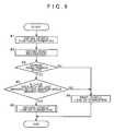
- FIG. 9 is a flowchart showing an exemplary lane determining method
- FIG. 10 is a flowchart showing an exemplary lane determining method.
- FIG. 11 is a view showing an example of a narrow-angle branch point where lane markings with deceleration zones are provided.
- FIG. 1 is a block diagram schematically showing the configuration of an exemplary navigation apparatus 1 including a lane determining device 2 .
- the lane determining device 2 is capable of determining a vehicle lane (a road lane on which a vehicle C is traveling), based on results of image recognition of lane markings included in obtained image information G (see FIG. 3 , FIG. 4 , and FIG. 7 ) and based on road information H obtained from a map database 20 .
- lane markings may include solid or dashed lines, or the like, provided as traffic lane border lines on both sides of the lane.
- the lane determining device 2 is capable of quickly determining the vehicle lane on which the vehicle C is traveling, by using results of image recognition of specific lane markings.
- the navigation apparatus 1 may perform predetermined navigation operations by referring to map information M obtained from the map database 20 and vehicle lane information R that is determined as a result of the lane determination by the lane determining device 2 .
- lane markings refer to solid or dashed white lines, yellow lines, and the like marked as border lines of the traffic lane on both sides or one side of the lane.
- the solid lines 40 , 42 , 43 , dashed lines 41 , and so on, shown in FIG. 6 are examples of such lane markings.
- lane markings The concept of the lane markings includes specific lane markings.
- “specific lane markings” refer to specific types of lane markings that are targets of image recognition in imaging order-based lane determination.
- Lane markings having characteristic shapes such as a lane marking with a zebra zone 44 and a lane marking with a deceleration zone 45 are examples of the “specific lane markings.”
- “branch point” refers to a point where two roads or more meet so that the vehicle can advance in at least two directions, and includes a narrow-angle branch point, an intersection, and the like.
- narrow-angle branch point refers to a branch point where conventional independent navigation using a GPS (Global Positioning System), a gyro sensor such as a yaw rate sensor, a G sensor, a vehicle speed sensor, and the like may have difficulty in determining in which direction the vehicle is advancing from the branch point, due to the configuration of the branch point (e.g., there is a narrow angle between the directions of two of the roads that meet at the branch point).
- lane means a traffic lane as well as branching roads connecting to a branch point.
- the navigation apparatus may, physically, functionally, and/or conceptually include, a vehicle position information obtaining section 3 , a road information obtaining section 4 , an image information obtaining section 5 , an image recognizing section 6 , a lane determining section 7 , and a navigation computing section 8 .
- Such sections may be implemented by applying various kinds of processing to input data, using hardware and/or software in a processor such as a CPU (controller).
- the navigation apparatus may include a map database 20 including, a device having a recording medium (memory) capable of recording information and its driving unit, such as, for example, a hard disk drive, a DVD drive including a DVD-ROM, or a CD drive including a CD-ROM.
- the map database 20 may store a plurality of pieces of the map information M, which are classified on a predetermined area basis, and pieces of road information H respectively corresponding to these pieces of the map information M.
- FIG. 2 is an explanatory view showing an example of the structure of the map information M and the road information H that are stored in the map database 20 .
- the map database 20 may store a road network layer m 1 , a road shape layer m 2 , and a road information layer m 3 .
- pieces of information stored in these layers m 1 to m 3 respectively form the map information M, and among them, the information stored in the road information layer m 3 forms the road information H.
- the road network information m 1 includes inter-road connection information.
- the road network information m 1 may include: information on a large number of nodes n having map position information expressed by longitude and latitude, and information on a large number of links k each linking two nodes n to form a road.
- each of the links k may have, as its link information, information on the road type (type such as an expressway, a toll road, a national road, a prefecture road, or the like), the length, and the like of the link.
- the road shape layer m 2 is stored in correspondence to the road network layer m 1 and shows the shape of each road.
- the road shape layer m 2 may include information on shape interpolation points s which are disposed between the two nodes n (on the link k) and indicate a detailed shape of each of the links k, information on a road width at each of the shape interpolation points s for showing a detailed shape of each road, and so on.
- the road information layer m 3 is formed in correspondence to the road network layer m 1 and the road shape layer m 2 and stores detailed information on each road. Examples of the information stored in the road information layer m 3 are information on each branch point (a narrow-angle branch point and the like), lane information regarding each road, feature information F regarding various kinds of features (lane markings and the like) provided on each road or around each road, and so on.
- the lane information may include information on the number of lanes of each road and lane width of each lane.
- the lane information may further include information on a positional relation of each lane in a plurality of roads branching off and connecting at the branch point and a connection relation of these roads (link angle, substantially straight connection, and so on), and so on.
- the feature information F includes position information and form information regarding each feature.
- the position information may have information on the position of a representative point of each feature on a map (longitude and latitude) and the direction of each feature.
- the form information has information on the shape, size, color, and the like of each feature.
- the feature information F includes type information indicating the type of each feature, and so on.
- Features shown by the feature information F may include road markings (e.g., painted markings) provided on a road surface.
- Examples of the features relating to the road markings include lane markings (various kinds of lane markings such as a solid line, a dashed line, a dual line, a lane marking with a zebra zone (striped), and a lane marking with a deceleration zone) provided along a road to demarcate each lane, traffic direction signs designating a traffic direction of each lane (various arrows such as a straight-ahead arrow, a right-turn arrow, and a left-turn arrow), a pedestrian crossing, a stop line, a speed indication, and the like.
- the features corresponding for which the feature information F is stored may also include various features such as a traffic signal, a traffic sign, an overpass, a tunnel, and the like, in addition to the above road markings.
- the road information H includes the feature information F such as the position information, the form information, and so on regarding the lane markings.
- the road information H regarding lane markings as traffic lane border lines marked on both sides or one side of the traffic lane and, in particular, the road information H regarding the specific lane markings are used.
- the road information H regarding a branch point, in particular, the road information H regarding a narrow-angle branch point is used.
- the vehicle position information obtaining section 3 functions as a vehicle position information obtaining unit obtaining vehicle position information S indicating a current position of the vehicle C.
- the vehicle position obtaining section 3 is connected to a GPS receiver 22 , a direction sensor 23 , and a distance sensor 24 .
- the GPS receiver 22 receives GPS signals from a GPS (Global Positioning System) satellite.
- the GPS signal is normally received every one second and is output to the vehicle position information obtaining section 3 .
- the vehicle position information obtaining section 3 analyses the signals received by the GPS receiver 22 from the GPS satellite, thereby being capable of obtaining information regarding a current position (longitude and latitude), a travel direction, a moving speed, and the like of the vehicle C.
- the direction sensor 23 detects the travel direction of the vehicle C or a change in the travel direction.
- the direction sensor 23 may be formed by a gyro sensor, a geomagnetic sensor, an optical rotation sensor or a rotation-type resistance sensor attached to a rotating portion of a steering handle, an angle sensor attached to a wheel portion, or the like.
- the direction sensor 23 outputs its detection result to the vehicle position information obtaining section 3 .
- the distance sensor 24 detects a speed and a moving distance of the vehicle C.
- the distance sensor 24 may be formed by a vehicle speed pulse sensor outputting a pulse signal every predetermined rotation amount of a drive shaft, a wheel, or the like of the vehicle C, a yaw/G sensor detecting acceleration of the vehicle C, a circuit integrating the detected acceleration, and so on.
- the distance sensor 24 outputs information on the vehicle speed and the moving distance, which are its detection results, to the vehicle position information obtaining section 3 .
- the vehicle position information obtaining section 3 performs calculations for locating the vehicle C by using a generally known method based on the outputs from the GPS receiver 22 , the direction sensor 23 , and the distance sensor 24 . Further, the vehicle position information obtaining section 3 obtains, from the map database 20 , the map information M regarding the vicinity of the vehicle position, and based on the map information M, performs correction for matching the vehicle position on a road shown in the map information M by generally known map matching. In this manner, the vehicle position information obtaining section 3 obtains the vehicle position information S including the information on the current position of the vehicle C (e.g., expressed by longitude and latitude), and the information on the travel direction of the vehicle C. The obtained vehicle position information S includes an error ascribable to detection accuracy and the like of each of the sensors 22 to 24 .
- the navigation apparatus 1 is structured so that the vehicle lane is determined by the later-described lane determining section 7 .
- the vehicle position information S obtained by the vehicle position information obtaining section 3 is output to the road information obtaining section 4 , the lane determining section 7 , and the navigation computing section 8 .
- the road information obtaining section 4 obtains necessary parts of the map information M and the feature information H including the feature information F from the map database 20 based on the vehicle position information S and so on obtained by the vehicle position information obtaining section 3 .
- the road information obtaining section 4 may obtain the road information H including the feature information F regarding features (lane markings and the like) which will be targets of image recognition processing by the image recognizing section 6 , to output the obtained information to the image recognizing section 6 .
- the road information obtaining section 4 may obtain the road information H regarding the vicinity of the vehicle position for use in the vehicle lane determination by the lane determining section 7 , and then may output the obtained information to the lane determining section 7 .
- the road information obtaining section 4 may obtain, from the map database 20 , the map information M regarding an area requested by the navigation computing section 8 for use in the navigation processing by the navigation computing section 8 , and may output the obtained information to the navigation computing section 8 .
- the road information H regarding the vicinity of the vehicle position obtained by the road information obtaining section 4 to be output to the lane determining section 7 may include information on lane markings (including specific lane markings) provided on the road where the vehicle C is traveling (see FIGS. 5 and 8 ), information regarding a branch point (especially, a narrow-angle branch point) present in the forward direction of the vehicle C, information on the number of lanes and widths of the lanes of the road, and so on.
- the image information obtaining section 5 obtains image information G (see FIGS. 3 , 4 , and 7 ) regarding the vicinity of the vehicle position imaged by an imaging device 21 .
- the imaging device 21 may be a camera or the like including an image sensor, and may be provided at a position where it is capable of capturing images of the lane markings (including the specific lane markings) on the road at least in the vicinity of the vehicle C.
- a back camera or the like may be suitably used.
- FIG. 3 shows image information G captured by the back camera from a point Y in FIG. 6
- FIG. 4 shows the image information G captured by the back camera from a point Z in FIG. 6
- the image information obtaining section 5 may receive analog image information captured by the imaging device 21 at predetermined time intervals and converts the analog image information into a digital signal to obtain the image information G.
- the time interval for receiving the image information G at this time may be set between about 10 ms to about 50 ms, for example. Consequently, the image information obtaining section 5 is capable of continuously obtaining a plurality of frames of the image information G captured by the imaging device 21 .
- the obtained plural frames of the image information G may be output to the image recognizing section 6 .
- the image recognizing section 6 performs image recognition processing on the image information G (see FIGS. 3 , 4 , and 7 ) obtained by the image information obtaining section 5 .
- the image recognizing section 6 may perform the image recognition processing of the lane markings (including the specific lane markings) as road markings provided on a surface of the road, by using the road information H obtained by the road information obtaining section 4 .
- the image recognizing section 6 may perform binarization processing, edge detection processing, and so on the obtained image information G to extract contour information of the features (lane markings) included in the image information G.
- the image recognizing section 6 may extract lane markings having the contour information matching the forms shown by the form information, based on the form information of the lane markings included in the road information H obtained by the road information obtaining section 4 .
- the image recognizing section 6 may calculate positional relationships between the vehicle C and the lane markings and may output information on the imaging order of the lane markings, information on the types of the lane markings, and information on the positional relationships with the vehicle C, as image recognition results to the lane determining section 7 .
- the positional relations between the vehicle C and the lane markings in the image information G can be calculated based on the positions of the lane markings in the image information G and based on information indicating a relation between the vehicle position and each of the positions in the image information G, which is calculated in advance based on a mounting position and a mounting angle of the imaging device 21 to the vehicle C, an angle of view of the imaging device 21 , and so on.
- the image recognizing section 6 may perform the image recognition processing of the lane markings (various lane markings such as solid lines 40 , dashed lines 41 , lane markings with zebra zones, and lane markings with deceleration zones) included in the image information G by using the feature information F included in the road information H obtained by the road information obtaining section 4 . Specifically, the feature information F regarding the lane markings in the vicinity of the vehicle position may be used. Then, the image recognizing section 6 may output the image recognition results regarding such lane markings to the lane determining section 7 .
- the lane markings various lane markings such as solid lines 40 , dashed lines 41 , lane markings with zebra zones, and lane markings with deceleration zones
- the lane determining section 7 determines the road lane in which the vehicle C is traveling based on the image recognition results by the image recognizing section 6 , the vehicle position information S obtained by the vehicle position information obtaining section 3 , and the road information H obtained by the road information obtaining section 4 .
- the lane determining section 7 may include a first lane determining part 7 a and a second lane determining part 7 b .
- the lane determining section 7 may output the vehicle lane information R as its determination result to the vehicle position information obtaining section 3 . Consequently, the navigation apparatus 1 is capable of obtaining the vehicle lane information R, and through the navigation computing section 8 and so on, it is capable of performing navigation operations such as road guidance and route search by referring to the vehicle lane information R.
- the lane determining section 7 may detect whether an area where it is highly likely that the vehicle lane cannot be determined exists in the forward direction of the vehicle C.
- the area where it is highly likely that the vehicle lane cannot be determined may be an area where a branch point (especially, a narrow-angle branch point) exists and the lane markings do not exist at all or do not partly exist before the branch point. Area A shown in FIG. 6 is an example of such an area.
- the first lane determining part 7 a performs first vehicle lane determination by using the lane markings according to a conventional method to determine the lane where the vehicle C is traveling.
- the second lane determining part 7 b performs second vehicle lane determination by using the specific lane markings after the vehicle C passes through such an area (e.g., area A), to determine the vehicle lane where the vehicle C is traveling.
- the first lane determining part 7 a performs the first vehicle lane determination when an area in which it is highly likely that the vehicle lane cannot be determined (for example, the area A in FIG. 6 ) does not exist in the forward direction of the vehicle C. That is, if a branch point does not exist or if all of lane markings are imaged in the vicinity of a branch point if any, the first vehicle lane determination is performed by using the lane markings such as the solid lines 40 or the dashed lines 41 existing on both sides of the lane.
- the first lane determining part 7 a performs the vehicle lane determination based on the image recognition results of the lane markings (white lines such as the solid lines 40 or the dashed lines 41 ) by the image recognizing section 6 and the feature information F of the lane markings in the vicinity of the vehicle C, which information is included in the road information H obtained by the road information obtaining section 4 .
- the first lane determining part 7 a performs the vehicle lane determination based on the image information G shown in FIG. 7 and the road information H shown in FIG. 8 .
- the first lane determining part 7 a specifies the lane on which the vehicle C is traveling, based on the type of the lane markings in the vicinity of the vehicle C and the positional relation between each of the lane markings and the vehicle C (which are included in the image recognition results by the image recognition section 6 ), and the feature information F on the lane markings included in the road information H regarding the vicinity of the vehicle position.
- the dashed lines 41 as the lane markings continuously appear on both sides of the vehicle C as shown in FIG.
- the obtained image information G In the obtained road information H regarding the vicinity of the vehicle C, a three-lane road is shown and among four lane markings, the outermost two lines are solid lines F 40 and the central two lines are dashed lines F 41 as shown in FIG. 8 . From this information, it can be determined that a lane where the vehicle C is traveling is the center lane among the three lanes.
- the dashed lines 41 exist on both sides of a widthwise image center which is the position of the vehicle C.
- the solid lines 40 exist respectively.
- the road information H see FIG. 8
- the road where the vehicle C is traveling has three lanes, and pieces of the feature information F of the solid lines F 40 as the lane markings exist on both sides of the road and pieces of the feature information F of the two dashed lines F 41 as the lane markings demarcating the lanes exist on the center portion of the road.
- the first lane determining part 7 a can determine that the lane where the vehicle C exists is the center lane among the three lanes, by comparing these pieces of information.
- the first lane determining part 7 a further determines whether the vehicle C has changed lanes, according to whether the vehicle C has crossed the lane marking, based on the position information regarding the lane markings which is included in the image recognition results by the image recognizing section 6 .
- the second lane determining part 7 b performs the second vehicle lane determination (imaging order-based lane determination) if an area in which it is highly likely that the vehicle lane cannot be determined exists in the forward direction of the vehicle C. For example, in the forward direction of the vehicle C, there is sometimes an area such as the area A in FIG. 6 in which a branch point (especially, a narrow-angle branch point) exists and the solid lines 40 or the dashed lines 41 as the lane markings do not exist at all or do not partly exist before the branch point. In such an area, the vehicle lane determination cannot be performed.
- the second lane determining part 7 b performs the vehicle lane determination based on the image recognition results by the image recognizing section 6 regarding the specific lane markings (the lane markings with the zebra zones 44 , the lane markings with the deceleration zones 45 , and the like), and the feature information F regarding the specific lane markings in the vicinity of the vehicle C (included in the road information H obtained by the road information obtaining section 4 ).
- candidates for a vehicle lane on which the vehicle C may travel after passing through the branch point are limited to the vehicle lane itself indicated by vehicle lane information R 1 which is obtained before the vehicle lane determination by the first lane determining part 7 a becomes impossible, and a lane adjacent to this vehicle lane. Consequently, a lane that is unlikely to become the vehicle lane can be excluded from the candidates, thereby realizing increased accuracy of the imaging order-based lane determination.
- the second lane determining part 7 b performs the lane determination based on the feature information F regarding the specific lane markings of the limited vehicle lanes, and the image recognition results of the specific lane markings included in the image information G.
- the second lane determining part 7 b is capable of specifying the vehicle lane that the vehicle C chooses after passing through the branch point, and outputting vehicle lane information R 2 .
- FIG. 6 is a view showing an example of a narrow-angle branch point where the lane markings with the zebra zones 44 as the specific lane markings are provided.
- FIG. 6 shows an example where the vehicle C passes through the point Y from the point X of a four-lane road to advance to a point Z.
- the second lane determining part 7 b detects, based on the road information H, that the narrow-angle branch point exists in a forward direction d and the lane markings such as the solid lines 40 and the dashed lines 41 do not exist at all or do not partly exist before the narrow-angle branch point (detects the area A). Therefore, the second lane determining part 7 b starts the second vehicle lane determination (imaging order-based lane determination).
- the candidates for a vehicle lane that the vehicle C may choose after passing through the narrow-angle branch point are limited to lanes d 1 , d 2 , d 3 to which the vehicle C can advance along the lane itself in the d direction and its adjacent lanes.
- the second lane determining part 7 b detects whether any lane marking with the zebra zone 44 is recognized in the image recognition results which are obtained based on pieces of the image information G sequentially imaged by the back camera of the vehicle C.
- the second lane determining part 7 b detects on which of the right and left of the vehicle C such a lane marking is recognized. If a plurality of the specific lane markings such as the lane markings with the zebra zones 44 are recognized, the second lane determining part 7 b detects in which order the plural lane markings with the zebra zones 44 are recognized. Then, the second lane determining part 7 b compares these detection results and the information on the positions and forms of the lane markings with the zebra zones 44 provided in the vicinity of the lanes d 1 , d 2 , d 3 , based on the information included in the road information H (see FIGS. 5 and 6 ).
- the lane marking with the zebra zone 44 is first detected on the right of the vehicle C (the left side in the image information G in FIG. 3 ) and subsequently the lane marking with the zebra zone 44 is detected on the left of the vehicle C (on the right in the image information G in FIG. 4 ).
- the vehicle C is traveling on the lane in the d 2 direction.
- the lane marking with the zebra zone 44 is first detected on the left of the vehicle C (on the right in the image information G) and subsequently the lane marking with the zebra zone 44 is detected on the right of the vehicle C (on the left in the image information G), it can be determined that the vehicle C is traveling on the lane in the d 1 direction. If, in the image information G, the lane marking with the zebra zone 44 is first detected on the left of the vehicle C (on the right in the image information G) and no lane marking with the zebra zone 44 is thereafter detected, it can be determined that the vehicle C is traveling on the lane in the d 3 direction.
- the vehicle lane can be determined based on the imaging order of the lane markings with the zebra zones 44 , the positions of the imaged lane markings with the zebra zones 44 relative to the vehicle C, the forms of the imaged lane markings with the zebra zones 44 , and the road information H regarding the lane markings with the zebra zones 44 . Therefore, even if the narrow-angle branch point exists in the forward direction d and the vehicle lane determination is difficult due to the absence of the solid lines 40 or the dashed lines 41 , quick vehicle lane determination is possible.
- the navigation computing section 8 is a processing unit operating according to an application program 8 a in order to execute navigation functions such as vehicle position display, route search from a place of departure to a destination, course guidance to the destination, and destination search.
- the navigation computing section 8 may perform processing such as obtaining the map information M regarding the vicinity of the vehicle C which is obtained from the map database 20 by the road information obtaining section 4 , and then displaying an image of a map on a display unit 25 and displaying a vehicle position mark on the image of the map in an overlaid manner, based on the vehicle position information S.
- the navigation computing section 8 may perform course guidance by using one of or both of the display unit 25 and an audio output device 26 based on a departure-to-destination route calculated by a generally known method and the vehicle position information S.
- the application program 8 a refers to the vehicle lane information R determined by the lane determining section 7 to perform the navigation operations such as the vehicle position display, the route search, and the course guidance. Specifically, for example, the application program 8 a may perform operations such as displaying the determined vehicle lane on the display unit 25 and stopping the course guidance necessitating impossible lane change according to the determined vehicle lane. Therefore, in this example, the navigation computing section 8 , the display unit 25 , and the audio output device 26 may function as a guidance information output section 27 .
- the navigation computing section 8 may be connected not only to these components but also to various known components usable with a navigation apparatus, such as a remote controller, a user interface such as a touch panel integrally provided with the display unit 25 , and so on, which are not shown.
- the exemplary method may be implemented, for example, by one or more components of the above-described navigation apparatus 1 .
- the exemplary structure of the above-described navigation apparatus 1 may be referenced in the description, it should be appreciated that the structure is exemplary and the exemplary method need not be limited by any of the above-described exemplary structure.
- the vehicle position information obtaining section 3 first obtains the vehicle position information S obtained from the GPS receiver 22 and so on (Step # 01 ).
- the road information H regarding an area within a predetermined distance in the forward direction d of the vehicle C is obtained from the map database 20 based on the vehicle position information S (Step # 02 ).
- the obtained road information H includes the information on the position and form of each lane marking. Then, it is detected, based on the road information H, whether or not there is a narrow-angle branch point within the predetermined distance (Step # 03 ).
- Step # 04 If it is determined, based on, for example, the information on the link angle of two links included in the road information H, that there is no narrow-angle branch point (Step # 03 : NO), the first vehicle lane determination is executed (Step # 04 ). On the other hand, if there is a narrow-angle branch point within the predetermined distance (Step # 03 : YES), it is detected whether there is an area (for example, the area A) with no lane markings (the solid lines 40 and the dashed lines 41 ) or without part of the lane markings before the narrow-angle branch point (Step # 05 ). If there is no such an area (Step # 05 : NO), the first vehicle lane determination is executed (Step # 04 ). On the other hand, if there is an area with no lane markings or without part of the lane markings before the narrow-angle branch point (Step # 05 : YES), the second vehicle lane determination is executed (Step # 06 ).
- the navigation apparatus 1 first limits the candidates for a vehicle lane that the vehicle C may choose after passing through the narrow-angle branch point, based on the vehicle lane information R 1 (obtained before the vehicle lane determination by the first lane determination part 7 a becomes impossible) (Step # 11 ). Consequently, a lane that is unlikely to become the vehicle lane can be excluded from the candidates, which can realize increased accuracy of the imaging order-based lane determination.
- the image information obtaining section 5 obtains the image information G of at least the lane markings imaged in the vicinity of the vehicle C (Step # 12 ).
- it is recognized whether any specific lane marking e.g., the lane marking with the zebra zone 44 , the lane marking with the deceleration zone 45 , or the like
- Step # 13 it is recognized whether any specific lane marking is imaged in this image information G. If no specific lane marking is recognized (Step # 14 : NO), the processing returns to Step # 12 , where the image information G is obtained. Therefore, the image information G is continuously obtained until the specific lane marking is recognized.
- Step # 14 YES
- the type of the specific lane marking is recognized (Step # 15 )
- the position of this specific lane marking is recognized, and if any other specific lane marking is recognized, the imaging order of the first recognized specific marking and the other specific lane marking is recognized (Step # 16 ). Consequently, the form of the specific lane markings in the image information G, the positional relation of the specific lane markings relative to the vehicle C (on which of the right and left of the vehicle C, each of the specific lane markings is detected), and the imaging order of the specific lane markings can be recognized.
- Step # 17 it is determined whether the lane on which the vehicle C is traveling after passing through the narrow-angle branch point has been determined. If the vehicle lane has not been determined (Step # 17 : NO), the processing goes to Step # 12 , where the image information G is obtained, and the second vehicle lane determination is continued. On the other hand, if the vehicle lane has been determined (Step # 17 : YES), the second vehicle lane determination is ended, and thus, the lane determination method ( FIG. 9 ) is ended.
- the specific lane marking is mainly the lane marking with the zebra zone 44 is described based on FIG. 6 .
- a lane marking with the deceleration zone 45 as shown in FIG. 11 may also be used.
- the lane marking with the deceleration zone 45 also has a characteristic shape and thus its image recognition is easy performed.
- the lane marking with the zebra zone 44 in the description using FIG. 3 to FIG. 10 is replaced by the lane marking with the deceleration zone 45 .
- the specific lane markings are not particularly limited, but may be any other lane markings, provided that they exist ahead of the branch point and have a characteristic shape, and their imaging order, positional relations relative to the vehicle C, and forms can be specified from the image recognition.
- the vehicle lane determining part 7 a determines the vehicle lane on the road where the vehicle C is traveling, based on the results of the image recognition of the image information G.
- the vehicle lane determining method by the first lane determining part 7 a is not limited to this.
- a structure where the first lane determining part 7 a performs the vehicle lane determination based on information from VICS® (Vehicle Information and Communication System), based on information from an optical beacon or the like sent from a transmitter provided on each lane of a road is also possible.
- VICS® Vehicle Information and Communication System
- the second lane determining part 7 b performs the vehicle lane determination after limiting the candidates for the vehicle lane on which the vehicle C may travel after passing through the narrow-angle branch point.
- a structure in which the second lane determining section 7 b performs the vehicle lane determination without limiting the candidates for the vehicle lane is also possible.
- the present invention in determining a lane on which a vehicle is traveling, by using image recognition results of lane markings, it is possible to quickly determine the lane on which the vehicle travels after passing through a branch point of a road even if no lane marking (solid or dashed white lines) as a basis of the recognition of the lane exists before the branch point. Accordingly, it is possible to provide a lane determining device and a lane determining method usable for a navigation apparatus and the like, that can accurately recognize the position of the vehicle immediately after the vehicle passes through the narrow-angle branch point.
Landscapes
- Engineering & Computer Science (AREA)
- Radar, Positioning & Navigation (AREA)
- Remote Sensing (AREA)
- Automation & Control Theory (AREA)
- General Physics & Mathematics (AREA)
- Physics & Mathematics (AREA)
- Computer Vision & Pattern Recognition (AREA)
- Navigation (AREA)
- Image Analysis (AREA)
- Traffic Control Systems (AREA)
- Image Processing (AREA)
- Inspection Of Paper Currency And Valuable Securities (AREA)
- Radar Systems Or Details Thereof (AREA)
Abstract
Description
Claims (13)
Applications Claiming Priority (2)
| Application Number | Priority Date | Filing Date | Title |
|---|---|---|---|
| JP2007-032352 | 2007-02-13 | ||
| JP2007032352A JP4861850B2 (en) | 2007-02-13 | 2007-02-13 | Lane determination device and lane determination method |
Publications (2)
| Publication Number | Publication Date |
|---|---|
| US20080208460A1 US20080208460A1 (en) | 2008-08-28 |
| US8112222B2 true US8112222B2 (en) | 2012-02-07 |
Family
ID=39462331
Family Applications (1)
| Application Number | Title | Priority Date | Filing Date |
|---|---|---|---|
| US12/068,807 Expired - Fee Related US8112222B2 (en) | 2007-02-13 | 2008-02-12 | Lane determining device, method, and program |
Country Status (6)
| Country | Link |
|---|---|
| US (1) | US8112222B2 (en) |
| EP (1) | EP1959236B1 (en) |
| JP (1) | JP4861850B2 (en) |
| CN (1) | CN101246010B (en) |
| AT (1) | ATE483953T1 (en) |
| DE (1) | DE602008002844D1 (en) |
Cited By (8)
| Publication number | Priority date | Publication date | Assignee | Title |
|---|---|---|---|---|
| US20100246889A1 (en) * | 2009-03-24 | 2010-09-30 | Hitachi Automotive Systems, Ltd. | Vehicle Driving Assistance Apparatus |
| US20100299063A1 (en) * | 2009-05-21 | 2010-11-25 | Clarion Co., Ltd. | Current Position Determining Device and Current Position Determining Method |
| US20110144907A1 (en) * | 2009-12-10 | 2011-06-16 | Aisin Aw Co., Ltd. | Travel guiding apparatus for vehicle, travel guiding method for vehicle, and computer-readable storage medium |
| US20150054952A1 (en) * | 2013-08-21 | 2015-02-26 | Mando Corporation | Back-sideways alarming system for vehicle and alarming control method thereof |
| US20150260530A1 (en) * | 2014-03-11 | 2015-09-17 | Volvo Car Corporation | Method and system for determining a position of a vehicle |
| US9460624B2 (en) | 2014-05-06 | 2016-10-04 | Toyota Motor Engineering & Manufacturing North America, Inc. | Method and apparatus for determining lane identification in a roadway |
| US20160347322A1 (en) * | 2013-12-04 | 2016-12-01 | Mobileye Vision Technologies Ltd. | Systems and methods for navigating a vehicle to a default lane |
| US9830517B2 (en) | 2014-06-19 | 2017-11-28 | Toyota Motor Engineering & Manufacturing North America, Inc. | Road branch detection and path selection for lane centering |
Families Citing this family (76)
| Publication number | Priority date | Publication date | Assignee | Title |
|---|---|---|---|---|
| JP4915739B2 (en) * | 2007-05-31 | 2012-04-11 | アイシン・エィ・ダブリュ株式会社 | Driving assistance device |
| JP5071737B2 (en) * | 2008-09-18 | 2012-11-14 | アイシン・エィ・ダブリュ株式会社 | Lane determination device, lane determination program, and navigation device using the same |
| JP4656456B2 (en) * | 2008-10-22 | 2011-03-23 | 日本電気株式会社 | Lane marking device, lane marking detection method, and lane marking detection program |
| US8929660B2 (en) | 2009-05-04 | 2015-01-06 | Tomtom North America, Inc. | Apparatus and method for lane marking analysis |
| JP5007840B2 (en) | 2009-05-22 | 2012-08-22 | トヨタ自動車株式会社 | Driving assistance device |
| KR101424421B1 (en) * | 2009-11-27 | 2014-08-01 | 도요타지도샤가부시키가이샤 | Drive assistance device and drive assistance method |
| DE102009060600A1 (en) * | 2009-12-23 | 2011-06-30 | Volkswagen AG, 38440 | Method for assigning driving strip of road to car, involves compensating marking characteristics that are extracted from digital map and determined by image processing device using classifier to find driving path regarding actual position |
| DE102010007091A1 (en) | 2010-02-06 | 2011-08-11 | Bayerische Motoren Werke Aktiengesellschaft, 80809 | Method for determining the position of a motor vehicle |
| KR20120113579A (en) * | 2011-04-05 | 2012-10-15 | 현대자동차주식회사 | Apparatus and method for displaying road guide information on the windshield |
| FR2986646B1 (en) * | 2012-02-03 | 2016-07-01 | Renault Sas | METHOD FOR DETERMINING THE POSITIONING OF A VEHICLE IN A WAY CIRCULATION HALL, AND METHODS OF DETECTING ALIGNMENT AND RISK OF COLLISION BETWEEN TWO VEHICLES |
| EP2629243A1 (en) * | 2012-02-15 | 2013-08-21 | Delphi Technologies, Inc. | Method for detecting and tracking lane markings |
| CN104296761B (en) * | 2012-05-30 | 2017-04-19 | 常州市新科汽车电子有限公司 | Method for matching main and side roads by navigator with high real-time performance |
| CN103954293B (en) * | 2012-05-30 | 2016-10-05 | 常州市新科汽车电子有限公司 | The method of work of navigator |
| CN103940436B (en) * | 2012-05-30 | 2017-02-01 | 常州市新科汽车电子有限公司 | Matching method of main and side roads of navigator with high instantaneity and accuracy |
| CN103954292B (en) * | 2012-05-30 | 2017-02-22 | 常州市新科汽车电子有限公司 | Navigator-based method for matching main road and side road of road according to traffic lane line |
| CN102722705B (en) * | 2012-06-12 | 2014-04-30 | 武汉大学 | Method for detecting multi-lane line on basis of random sample consensus (RANSAC) algorithm |
| CN104316069A (en) * | 2012-06-26 | 2015-01-28 | 上海安悦四维信息技术有限公司 | A vehicle navigation device and a navigation method for identifying main and auxiliary roads |
| CN102735256A (en) * | 2012-06-26 | 2012-10-17 | 上海安悦四维信息技术有限公司 | Vehicle-mounted navigation device and navigation method for identifying main and auxiliary roads |
| JP5924508B2 (en) * | 2012-07-06 | 2016-05-25 | トヨタ自動車株式会社 | Vehicle travel control device |
| CN104508708B (en) * | 2012-08-13 | 2017-06-16 | 本田技研工业株式会社 | Road environment recognition device |
| CN103050011B (en) * | 2012-12-15 | 2014-10-22 | 浙江交通职业技术学院 | Driveway information indicating system |
| CN103900597A (en) * | 2012-12-28 | 2014-07-02 | 环达电脑(上海)有限公司 | Navigation system and navigation method of travel direction |
| KR101836246B1 (en) * | 2012-12-31 | 2018-03-08 | 현대자동차 주식회사 | Current Lane Detecting Method |
| DE102013207658A1 (en) * | 2013-04-26 | 2014-10-30 | Bayerische Motoren Werke Aktiengesellschaft | Method for determining a lane course of a traffic lane |
| CN104422426B (en) * | 2013-08-30 | 2017-07-11 | 博世汽车部件(苏州)有限公司 | The method and apparatus that vehicle navigation information is provided in overpass region |
| US9677898B2 (en) | 2014-06-17 | 2017-06-13 | Think Ware Corporation | Electronic apparatus and control method thereof |
| KR102255432B1 (en) * | 2014-06-17 | 2021-05-24 | 팅크웨어(주) | Electronic apparatus and control method thereof |
| CN104217598A (en) * | 2014-09-04 | 2014-12-17 | 苏州大学 | Lane direction prompting device |
| JP6344275B2 (en) * | 2015-03-18 | 2018-06-20 | トヨタ自動車株式会社 | Vehicle control device |
| CN107636751B (en) * | 2015-06-15 | 2021-06-04 | 三菱电机株式会社 | Travel lane determination device and travel lane determination method |
| US9771071B2 (en) * | 2015-11-19 | 2017-09-26 | Ford Global Technologies, Llc | Dynamic lane positioning for improved biker safety |
| CN105588576B (en) * | 2015-12-15 | 2019-02-05 | 招商局重庆交通科研设计院有限公司 | A lane-level navigation method and system |
| US9766344B2 (en) * | 2015-12-22 | 2017-09-19 | Honda Motor Co., Ltd. | Multipath error correction |
| KR102158169B1 (en) * | 2016-01-06 | 2020-09-22 | 주식회사 디젠 | Lane detection apparatus |
| JP2017161501A (en) * | 2016-03-07 | 2017-09-14 | 株式会社デンソー | Travelling location detection device and travelling location detection method |
| JP6628189B2 (en) * | 2016-05-19 | 2020-01-08 | パナソニックIpマネジメント株式会社 | Detection device and detection method |
| CN106092123B (en) * | 2016-06-06 | 2019-02-15 | 广东中星电子有限公司 | A kind of video navigation method and device |
| WO2018031673A1 (en) * | 2016-08-10 | 2018-02-15 | Surround.IO Corporation | Method and system for providing information via collected and stored metadata using inferred attentional model |
| KR101946334B1 (en) * | 2016-12-07 | 2019-05-10 | 주식회사 만도 | Apparatus and method for normal route driving of vehicle |
| CN106530794B (en) * | 2016-12-28 | 2019-03-01 | 上海仪电数字技术股份有限公司 | The automatic identification and calibration method and system of carriage way |
| KR102826622B1 (en) * | 2017-01-17 | 2025-06-27 | 팅크웨어(주) | Method, apparatus, electronic apparatus, computer program and computer readable recording medium for providing driving guide using a photographed image of a camera |
| CN108303103B (en) | 2017-02-07 | 2020-02-07 | 腾讯科技(深圳)有限公司 | Method and device for determining target lane |
| US20180273051A1 (en) * | 2017-03-24 | 2018-09-27 | Bendix Commercial Vehicle Sytems LLC | Controller and Method of Setting an Intervention Zone in a Lane Departure Warning System |
| CN110431609B (en) * | 2017-03-27 | 2022-01-11 | 三菱电机株式会社 | Vehicle position estimation device |
| DE102017207544A1 (en) * | 2017-05-04 | 2018-11-08 | Volkswagen Aktiengesellschaft | METHOD, DEVICES AND COMPUTER READABLE STORAGE MEDIUM WITH INSTRUCTIONS FOR LOCATING A DATE MENTIONED BY A MOTOR VEHICLE |
| WO2018232672A1 (en) * | 2017-06-21 | 2018-12-27 | 深圳支点电子智能科技有限公司 | Method and device for determining vehicle travel road |
| JP6627135B2 (en) * | 2017-06-22 | 2020-01-08 | 本田技研工業株式会社 | Vehicle position determination device |
| US10553110B2 (en) | 2017-06-23 | 2020-02-04 | Here Global B.V. | Detection and estimation of variable speed signs |
| CN109270927B (en) * | 2017-07-17 | 2022-03-11 | 阿里巴巴(中国)有限公司 | Road data generation method and device |
| JP6780611B2 (en) | 2017-08-25 | 2020-11-04 | トヨタ自動車株式会社 | Autonomous driving device |
| JP6978176B2 (en) * | 2017-12-26 | 2021-12-08 | アルパイン株式会社 | Electronic device |
| CN110120081B (en) * | 2018-02-07 | 2023-04-25 | 北京四维图新科技股份有限公司 | Method, device and storage equipment for generating lane markings of electronic map |
| CN108345019A (en) * | 2018-04-20 | 2018-07-31 | 长安大学 | The positioning device and method in a kind of vehicle place track |
| CN109032125B (en) * | 2018-05-31 | 2021-09-10 | 上海工程技术大学 | Navigation method of visual AGV |
| JP7136043B2 (en) * | 2018-08-31 | 2022-09-13 | 株式会社デンソー | TRAVEL TRACK DATA GENERATOR AND TRAVEL DATA GENERATION PROGRAM IN INTERSECTION |
| US12516948B2 (en) | 2018-11-26 | 2026-01-06 | Mobileye Vision Technologies Ltd. | Lane mapping and navigation |
| CN111381269B (en) * | 2018-12-28 | 2023-09-05 | 沈阳美行科技股份有限公司 | Vehicle positioning method, device, electronic equipment and computer readable storage medium |
| WO2020172875A1 (en) * | 2019-02-28 | 2020-09-03 | 深圳市大疆创新科技有限公司 | Method for extracting road structure information, unmanned aerial vehicle, and automatic driving system |
| CN109916414B (en) * | 2019-03-29 | 2021-07-09 | 百度在线网络技术(北京)有限公司 | Map matching method, apparatus, device and medium |
| CN110281945B (en) * | 2019-06-28 | 2021-01-15 | 信利光电股份有限公司 | Vehicle driving auxiliary monitoring method, device and system |
| CN110398255A (en) * | 2019-07-05 | 2019-11-01 | 上海博泰悦臻网络技术服务有限公司 | Localization method, device and vehicle |
| DE102019118788A1 (en) * | 2019-07-11 | 2021-01-14 | Valeo Schalter Und Sensoren Gmbh | Selecting a lane following mode |
| JP7149234B2 (en) * | 2019-07-22 | 2022-10-06 | 本田技研工業株式会社 | Lane data generation device, position specifying device, lane data generation method, and position specifying method |
| CN110455298B (en) * | 2019-08-14 | 2022-02-08 | 灵动科技(北京)有限公司 | Positioning method and positioning system for vehicle |
| EP3798575A1 (en) * | 2019-09-26 | 2021-03-31 | Zenuity AB | Method and system for determining localization of a vehicle on a road |
| CN113032500B (en) * | 2019-12-25 | 2023-10-17 | 沈阳美行科技股份有限公司 | Vehicle positioning method, device, computer equipment and storage medium |
| CN113033267B (en) * | 2019-12-25 | 2023-07-21 | 沈阳美行科技股份有限公司 | Vehicle positioning method, device, computer equipment and storage medium |
| CN111559373B (en) * | 2020-04-26 | 2021-08-13 | 东风汽车集团有限公司 | A vehicle active steering control method |
| CN111595358B (en) | 2020-06-05 | 2022-03-29 | 百度在线网络技术(北京)有限公司 | Navigation data processing method, route guidance method, device and storage medium |
| FR3113879A1 (en) * | 2020-09-10 | 2022-03-11 | Psa Automobiles Sa | Method and device for partitioning a widening zone of a traffic lane delimited by two edges. |
| JP7216699B2 (en) * | 2020-12-28 | 2023-02-01 | 本田技研工業株式会社 | VEHICLE CONTROL SYSTEM AND OWN LANE SPECIFICATION METHOD |
| JP7591436B2 (en) * | 2021-03-10 | 2024-11-28 | 日産自動車株式会社 | Driving support method and driving support device |
| JP7576492B2 (en) * | 2021-03-10 | 2024-10-31 | 日産自動車株式会社 | Driving support method and driving support device |
| CN113392762B (en) * | 2021-06-15 | 2024-04-26 | 北京纵目安驰智能科技有限公司 | Intersection detection method, system, terminal and computer readable storage medium |
| CN113865610A (en) * | 2021-09-30 | 2021-12-31 | 北京百度网讯科技有限公司 | Method, apparatus, device, medium and product for generating navigation information |
| CN114323005B (en) * | 2021-12-28 | 2023-08-11 | 上汽大众汽车有限公司 | A Locating Method for Slightly Diverging Roads |
Citations (9)
| Publication number | Priority date | Publication date | Assignee | Title |
|---|---|---|---|---|
| JPH1172337A (en) | 1997-08-28 | 1999-03-16 | Mitsubishi Motors Corp | Travel lane recognition device |
| JP2000105898A (en) | 1998-02-18 | 2000-04-11 | Equos Research Co Ltd | VEHICLE CONTROL DEVICE, VEHICLE CONTROL METHOD, AND COMPUTER-READABLE MEDIUM RECORDING PROGRAM FOR CAUSING COMPUTER TO EXECUTE VEHICLE CONTROL METHOD |
| US20010056326A1 (en) * | 2000-04-11 | 2001-12-27 | Keiichi Kimura | Navigation apparatus, method for map matching performed in the navigation apparatus, and computer-readable medium storing a program for executing the method |
| US6577334B1 (en) * | 1998-02-18 | 2003-06-10 | Kabushikikaisha Equos Research | Vehicle control |
| EP1605404A2 (en) | 2004-06-02 | 2005-12-14 | Toyota Jidosha Kabushiki Kaisha | Lane boundary detector |
| EP1674827A1 (en) | 2004-12-24 | 2006-06-28 | Aisin Aw Co., Ltd. | System for detecting a lane change of a vehicle |
| JP2007003286A (en) | 2005-06-22 | 2007-01-11 | Nissan Motor Co Ltd | Own vehicle position detection device, navigation device, deceleration control device, and own vehicle position detection method |
| US20090024320A1 (en) * | 2004-12-27 | 2009-01-22 | Masaki Nakamura | Navigation apparatus |
| US7668341B2 (en) * | 2005-01-28 | 2010-02-23 | Aisin Aw Co., Ltd. | Image recognition apparatus and image recognition method |
Family Cites Families (1)
| Publication number | Priority date | Publication date | Assignee | Title |
|---|---|---|---|---|
| CN1254956C (en) * | 2004-04-15 | 2006-05-03 | 上海交通大学 | Calibrating method of pick-up device under condition of traffic monitering |
-
2007
- 2007-02-13 JP JP2007032352A patent/JP4861850B2/en not_active Expired - Fee Related
-
2008
- 2008-02-12 EP EP08151322A patent/EP1959236B1/en not_active Not-in-force
- 2008-02-12 US US12/068,807 patent/US8112222B2/en not_active Expired - Fee Related
- 2008-02-12 AT AT08151322T patent/ATE483953T1/en not_active IP Right Cessation
- 2008-02-12 DE DE602008002844T patent/DE602008002844D1/en active Active
- 2008-02-13 CN CN2008100096085A patent/CN101246010B/en not_active Expired - Fee Related
Patent Citations (9)
| Publication number | Priority date | Publication date | Assignee | Title |
|---|---|---|---|---|
| JPH1172337A (en) | 1997-08-28 | 1999-03-16 | Mitsubishi Motors Corp | Travel lane recognition device |
| JP2000105898A (en) | 1998-02-18 | 2000-04-11 | Equos Research Co Ltd | VEHICLE CONTROL DEVICE, VEHICLE CONTROL METHOD, AND COMPUTER-READABLE MEDIUM RECORDING PROGRAM FOR CAUSING COMPUTER TO EXECUTE VEHICLE CONTROL METHOD |
| US6577334B1 (en) * | 1998-02-18 | 2003-06-10 | Kabushikikaisha Equos Research | Vehicle control |
| US20010056326A1 (en) * | 2000-04-11 | 2001-12-27 | Keiichi Kimura | Navigation apparatus, method for map matching performed in the navigation apparatus, and computer-readable medium storing a program for executing the method |
| EP1605404A2 (en) | 2004-06-02 | 2005-12-14 | Toyota Jidosha Kabushiki Kaisha | Lane boundary detector |
| EP1674827A1 (en) | 2004-12-24 | 2006-06-28 | Aisin Aw Co., Ltd. | System for detecting a lane change of a vehicle |
| US20090024320A1 (en) * | 2004-12-27 | 2009-01-22 | Masaki Nakamura | Navigation apparatus |
| US7668341B2 (en) * | 2005-01-28 | 2010-02-23 | Aisin Aw Co., Ltd. | Image recognition apparatus and image recognition method |
| JP2007003286A (en) | 2005-06-22 | 2007-01-11 | Nissan Motor Co Ltd | Own vehicle position detection device, navigation device, deceleration control device, and own vehicle position detection method |
Non-Patent Citations (1)
| Title |
|---|
| Japanese Patent Office, Notification of Reason(s) for Refusal mailed May 6, 2011 in Japanese Patent Application No. 2007-032352 w/Partial English-language Translation. |
Cited By (15)
| Publication number | Priority date | Publication date | Assignee | Title |
|---|---|---|---|---|
| US20100246889A1 (en) * | 2009-03-24 | 2010-09-30 | Hitachi Automotive Systems, Ltd. | Vehicle Driving Assistance Apparatus |
| US8385600B2 (en) * | 2009-03-24 | 2013-02-26 | Hitachi Automotive Systems, Ltd. | Vehicle driving assistance apparatus |
| US20100299063A1 (en) * | 2009-05-21 | 2010-11-25 | Clarion Co., Ltd. | Current Position Determining Device and Current Position Determining Method |
| US8473201B2 (en) * | 2009-05-21 | 2013-06-25 | Clarion Co., Ltd. | Current position determining device and current position determining method for correcting estimated position based on detected lane change at road branch |
| US20110144907A1 (en) * | 2009-12-10 | 2011-06-16 | Aisin Aw Co., Ltd. | Travel guiding apparatus for vehicle, travel guiding method for vehicle, and computer-readable storage medium |
| US8504293B2 (en) * | 2009-12-10 | 2013-08-06 | Aisin Aw Co., Ltd. | Travel guiding apparatus for vehicle, travel guiding method for vehicle, and computer-readable storage medium |
| US20150054952A1 (en) * | 2013-08-21 | 2015-02-26 | Mando Corporation | Back-sideways alarming system for vehicle and alarming control method thereof |
| US9569970B2 (en) * | 2013-08-21 | 2017-02-14 | Mando Corporation | Back-sideways alarming system for vehicle and alarming control method thereof |
| US20160347322A1 (en) * | 2013-12-04 | 2016-12-01 | Mobileye Vision Technologies Ltd. | Systems and methods for navigating a vehicle to a default lane |
| US9656673B2 (en) * | 2013-12-04 | 2017-05-23 | Mobileye Vision Technologies Ltd. | Systems and methods for navigating a vehicle to a default lane |
| US20150260530A1 (en) * | 2014-03-11 | 2015-09-17 | Volvo Car Corporation | Method and system for determining a position of a vehicle |
| US9644975B2 (en) * | 2014-03-11 | 2017-05-09 | Volvo Car Corporation | Method and system for determining a position of a vehicle |
| US9460624B2 (en) | 2014-05-06 | 2016-10-04 | Toyota Motor Engineering & Manufacturing North America, Inc. | Method and apparatus for determining lane identification in a roadway |
| US10074281B2 (en) | 2014-05-06 | 2018-09-11 | Toyota Motor Engineering & Manufacturing North America, Inc. | Method and apparatus for determining lane identification in a roadway |
| US9830517B2 (en) | 2014-06-19 | 2017-11-28 | Toyota Motor Engineering & Manufacturing North America, Inc. | Road branch detection and path selection for lane centering |
Also Published As
| Publication number | Publication date |
|---|---|
| EP1959236B1 (en) | 2010-10-06 |
| CN101246010A (en) | 2008-08-20 |
| JP2008197905A (en) | 2008-08-28 |
| DE602008002844D1 (en) | 2010-11-18 |
| CN101246010B (en) | 2012-09-26 |
| EP1959236A1 (en) | 2008-08-20 |
| US20080208460A1 (en) | 2008-08-28 |
| JP4861850B2 (en) | 2012-01-25 |
| ATE483953T1 (en) | 2010-10-15 |
Similar Documents
| Publication | Publication Date | Title |
|---|---|---|
| US8112222B2 (en) | Lane determining device, method, and program | |
| JP4446204B2 (en) | Vehicle navigation apparatus and vehicle navigation program | |
| US8346473B2 (en) | Lane determining device, lane determining method and navigation apparatus using the same | |
| JP4861851B2 (en) | Lane determination device, lane determination method, and navigation device using the same | |
| CN101447019B (en) | Image recognition device and image recognition method | |
| JP4366664B2 (en) | Own vehicle position recognition device and own vehicle position recognition program | |
| JP5229293B2 (en) | Vehicle driving support device | |
| JP4738360B2 (en) | Lane determination device, lane determination method, and navigation device using the same | |
| JP2011013039A (en) | Lane determination device and navigation system | |
| JP2011122936A (en) | Vehicle travel guiding device, method and computer program | |
| JP2005214883A (en) | Car navigation system | |
| JP4953012B2 (en) | Image recognition device, program for image recognition device, navigation device using the same, and program for navigation device | |
| US7747385B2 (en) | Traveling condition determination device | |
| JP4875509B2 (en) | Navigation device and navigation method | |
| JP4596566B2 (en) | Self-vehicle information recognition device and self-vehicle information recognition method | |
| JP2010071810A (en) | Lane determining device and lane determination program, and navigation apparatus using the lane determining device | |
| JP5013214B2 (en) | Lane determination device, lane determination program, and navigation device using the same | |
| JP2009058430A (en) | Navigation apparatus and program | |
| JP3864729B2 (en) | Departure determination device for vehicles | |
| JP2008298622A (en) | Feature recognition device, feature recognition method, lane determination device and lane determination method using the same | |
| JP5308810B2 (en) | In-vehicle video display | |
| JP4943246B2 (en) | Lane determination device, lane determination program, and navigation device using the same |
Legal Events
| Date | Code | Title | Description |
|---|---|---|---|
| AS | Assignment |
Owner name: AISIN AW CO., LTD.,JAPAN Free format text: ASSIGNMENT OF ASSIGNORS INTEREST;ASSIGNORS:NAKAO, KOICHI;NAKAMURA, MASAKI;NAKAMURA, MOTOHIRO;SIGNING DATES FROM 20080328 TO 20080407;REEL/FRAME:020896/0162 Owner name: AISIN AW CO., LTD., JAPAN Free format text: ASSIGNMENT OF ASSIGNORS INTEREST;ASSIGNORS:NAKAO, KOICHI;NAKAMURA, MASAKI;NAKAMURA, MOTOHIRO;SIGNING DATES FROM 20080328 TO 20080407;REEL/FRAME:020896/0162 |
|
| FEPP | Fee payment procedure |
Free format text: PAYOR NUMBER ASSIGNED (ORIGINAL EVENT CODE: ASPN); ENTITY STATUS OF PATENT OWNER: LARGE ENTITY |
|
| ZAAA | Notice of allowance and fees due |
Free format text: ORIGINAL CODE: NOA |
|
| ZAAB | Notice of allowance mailed |
Free format text: ORIGINAL CODE: MN/=. |
|
| ZAAA | Notice of allowance and fees due |
Free format text: ORIGINAL CODE: NOA |
|
| STCF | Information on status: patent grant |
Free format text: PATENTED CASE |
|
| FPAY | Fee payment |
Year of fee payment: 4 |
|
| MAFP | Maintenance fee payment |
Free format text: PAYMENT OF MAINTENANCE FEE, 8TH YEAR, LARGE ENTITY (ORIGINAL EVENT CODE: M1552); ENTITY STATUS OF PATENT OWNER: LARGE ENTITY Year of fee payment: 8 |
|
| FEPP | Fee payment procedure |
Free format text: MAINTENANCE FEE REMINDER MAILED (ORIGINAL EVENT CODE: REM.); ENTITY STATUS OF PATENT OWNER: LARGE ENTITY |
|
| LAPS | Lapse for failure to pay maintenance fees |
Free format text: PATENT EXPIRED FOR FAILURE TO PAY MAINTENANCE FEES (ORIGINAL EVENT CODE: EXP.); ENTITY STATUS OF PATENT OWNER: LARGE ENTITY |
|
| STCH | Information on status: patent discontinuation |
Free format text: PATENT EXPIRED DUE TO NONPAYMENT OF MAINTENANCE FEES UNDER 37 CFR 1.362 |
|
| FP | Lapsed due to failure to pay maintenance fee |
Effective date: 20240207 |