US8109434B2 - Cash transaction machine - Google Patents
Cash transaction machine Download PDFInfo
- Publication number
- US8109434B2 US8109434B2 US11/967,431 US96743107A US8109434B2 US 8109434 B2 US8109434 B2 US 8109434B2 US 96743107 A US96743107 A US 96743107A US 8109434 B2 US8109434 B2 US 8109434B2
- Authority
- US
- United States
- Prior art keywords
- financial module
- door
- module
- opening
- financial
- Prior art date
- Legal status (The legal status is an assumption and is not a legal conclusion. Google has not performed a legal analysis and makes no representation as to the accuracy of the status listed.)
- Expired - Fee Related, expires
Links
- 230000008878 coupling Effects 0.000 claims description 33
- 238000010168 coupling process Methods 0.000 claims description 33
- 238000005859 coupling reaction Methods 0.000 claims description 33
- 238000000151 deposition Methods 0.000 description 19
- 230000008439 repair process Effects 0.000 description 6
- 230000007246 mechanism Effects 0.000 description 4
- 230000008859 change Effects 0.000 description 2
- 238000006073 displacement reaction Methods 0.000 description 2
- 238000012423 maintenance Methods 0.000 description 2
- 239000010687 lubricating oil Substances 0.000 description 1
Images


Classifications
-
- G—PHYSICS
- G07—CHECKING-DEVICES
- G07F—COIN-FREED OR LIKE APPARATUS
- G07F19/00—Complete banking systems; Coded card-freed arrangements adapted for dispensing or receiving monies or the like and posting such transactions to existing accounts, e.g. automatic teller machines
- G07F19/20—Automatic teller machines [ATMs]
- G07F19/205—Housing aspects of ATMs
-
- G—PHYSICS
- G07—CHECKING-DEVICES
- G07F—COIN-FREED OR LIKE APPARATUS
- G07F19/00—Complete banking systems; Coded card-freed arrangements adapted for dispensing or receiving monies or the like and posting such transactions to existing accounts, e.g. automatic teller machines
- G07F19/20—Automatic teller machines [ATMs]
-
- G—PHYSICS
- G07—CHECKING-DEVICES
- G07D—HANDLING OF COINS OR VALUABLE PAPERS, e.g. TESTING, SORTING BY DENOMINATIONS, COUNTING, DISPENSING, CHANGING OR DEPOSITING
- G07D2211/00—Paper-money handling devices
Definitions
- the present invention relates to a cash transaction machine, and more particularly, to a cash transaction machine that includes a door on a side of the cash transaction machine.
- a cash transaction machine can be installed in a financial institution such as a bank in order to provide convenient financial services for banking customers.
- the cash transaction machine may be installed in a convenient store, a public place, and the like. Therefore, banking customers may readily deposit and withdraw money using the cash transaction machine.
- the banking customers may use various types of financial services such as checking of the balance, a transfer service, and the like.
- the cash transaction machine includes various types of modules, such as a dispensing module, a depositing module, a card reader, a bankbook arrangement module, a main controller, and the like.
- the independently installed modules may be electrically connected to the main controller and perform cooperative functions.
- a door is provided to open and provide access to the inside of the cash transaction machine.
- the door is provided on a front surface or a rear surface of the cash transaction machine.
- the door needs to be provided on a side of the cash transaction machine.
- the cash transaction machine that includes the door on the side of the cash transaction machine may be referred to as a side open-and-close type cash transaction machine.
- the dispensing module and the depositing module are integrally formed with the door.
- both the dispensing module and the depositing module may be simultaneously exposed.
- the conventional side open-and-close type cash transaction machine includes the dispensing module that is disposed inside the door and the depositing module that is disposed inside the dispensing module. Therefore, both the dispensing module and the depositing module are provided in the door.
- both modules are turned together with the door and are externally exposed. Conversely, when the door is closed, both the modules move into the cash transaction machine to designated internal mounting locations.
- the dispensing module and the depositing module are attached to the door, various types of problems may occur. For example, since the dispensing module and the depositing module are attached to the door, disadvantages may occur in maintenance and repair. When the dispensing module needs to be repaired and maintained, the depositing module that is attached to the dispensing module must be separated from the dispensing module. Also, since the dispensing module and the depositing module are attached together, the width of the door must be larger than the size of the dispensing module or the size of the depositing module in order to open the door while preventing the depositing module from becoming caught on the door. Therefore, it may be difficult to reduce the front and rear length of the cash transaction machine.
- the weight of the dispensing module and the depositing module may damage a hinge of the door.
- the dispensing module and the depositing module may deviate from the centroid. In this case, the weight distribution may be unbalanced in the cash transaction machine.
- An aspect of the present invention provides a cash transaction machine that can independently include a plurality of modules and thus can effectively manage each of the modules.
- Another aspect of the present invention also provides a cash transaction machine that does not need an increase in the size and length of the front and rear of the cash transaction machine, and that can be manufactured within a predetermined size.
- a cash transaction machine including: a body including an opening on a side of the body; a door being mounted on the body to open and close the opening; a first financial module being integrally formed with the door in the door to be externally exposed when the door is opened; and a second financial module being provided in the body, separate from the door to move toward the opening when the door is opened.
- the body may be referred as a type of housing that receives a plurality of modules in the cash transaction machine.
- the opening may be formed on the side of the body and may be opened and closed by the door.
- the plurality of financial modules may be disposed in the body.
- the financial modules may include a dispensing module, a depositing module, a main controller, a card reader, a bankbook arrangement module, and the like. Specifically, the financial modules may be independently provided in the cash transaction machine.
- the first financial module is disposed on the inner surface of the door. Therefore, when the door is opened, the first financial module may be externally exposed together with the door.
- the second financial module is provided in the body, separate from the door. Also, the second financial module may move toward an outside, that is, the opening, depending on the necessity of an operator. Therefore, the operator does not need to separate the second financial module in order to repair or maintain the first financial module. Since a side surface of the first financial module is directly exposed, the first financial module may be more variously designed. Also, when the door is opened, only the first financial module is exposed and thus it is possible to reduce the load to the door. The operator may easily open and close the door.
- the first financial module When the door is opened, the first financial module is also externally exposed. However, a separate operation is needed to take out the second financial module from the cash transaction machine. Generally, the operator may directly move the second financial module to the outside using a knob formed on the second financial module. Depending on embodiments, it is possible to construct the second financial module to automatically move.
- the second financial module may move toward the outside by a predetermined guide member. Also, the second financial module may be slidable with respect to the guide member and thereby additionally move to the outside.
- FIG. 1 is a perspective view illustrating a cash transaction machine according to an exemplary embodiment of the present invention
- FIG. 2 is a perspective view illustrating a state where a door of the cash transaction machine of FIG. 1 is opened;
- FIG. 3 is a top view illustrating the displacement of a first financial module and a second financial module in the cash transaction machine of FIG. 1 ;
- FIG. 4 is a cross-sectional view for describing a portion IV-IV of FIG. 3 ;
- FIGS. 5 through 7 are top views for describing the movement mechanism of the first financial module and the second financial module of FIG. 3 ;
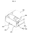
- FIG. 8 is a partially enlarged perspective view for describing a temporary fixing member of FIG. 6 ;
- FIGS. 9A and 9B are cross-sectional views for describing the operating mechanism of the temporary fixing member of FIG. 8 .
- FIG. 1 is a perspective view illustrating a cash transaction machine 100 according to an exemplary embodiment of the present invention
- FIG. 2 is a perspective view illustrating a state where a door 140 of the cash transaction machine 100 is opened.
- the cash transaction machine 100 includes a body 120 that includes an opening on a side of the body 120 , the door 140 that opens and closes the opening, a first financial module 220 that is integrally provided formed with the door 140 in the door 140 to be externally exposed when the door 140 is opened, and a second financial module 240 that is provided in the body 120 , separate from the door 140 to move toward the opening and thereby be externally exposed when the door is opened 140 .
- a manipulation portion 160 , a dispensing portion 182 , and a depositing portion 184 are formed on an external surface of the body 120 .
- a user may enter an amount of withdrawal, a password, and the like using the manipulation portion 160 .
- the user may withdraw or deposit bills via the dispensing portion 182 and the depositing portion 184 .
- the first financial module 220 and the second financial module 240 may denote a dispensing module and a depositing module respectively.
- the dispensing portion 182 and the depositing portion 184 are formed on the body 120 .
- the present invention is not limited thereto. Therefore, the first financial module 220 and the second financial module 240 may replace the above-described other modules and be variously modified depending on embodiments.
- the opening is formed on the side of the body 120 to pass the first financial module 220 and the second financial module 240 .
- the door 140 is provided on one side of the opening.
- the door 140 may be movably provided on the left or right side of the opening.
- the door 140 may be provided adjacent to the side where the dispensing portion 182 is formed. This is because an outlet of the first financial module 220 must be positioned adjacent to the dispensing portion 182 when the door 140 is closed.
- a lock assembly 142 may be mounted onto the door 140 to lock the door 140 .
- only one second financial module 240 is provided separate from the body 240 .
- the present invention is not limited thereto. Specifically, at least two second financial modules may be provided in the body 120 . Also, separate equipments may be installed in the first financial module 220 .
- the first financial module 220 is integrally formed with the door 140 on the inner surface of the door 140 . When the door 140 is opened, the first financial module 220 may be externally exposed together with the door 140 . Also, the second financial module 240 may be further provided in the body 120 . The second financial module 240 is provided in the body 120 in parallel with the first financial module 220 . The second financial module 240 may move, separate from the first financial module 220 , to be externally exposed.
- the second financial module 240 is provided separate from the first financial module 220 . Therefore, when the first financial module 220 or the second financial module 240 needs to be repaired or replaced, it is possible to separately repair or replace the first financial module 220 and the second financial module 240 . Specifically, each of the first financial module 220 and the second financial module 240 may be independently exposed to the outside. Therefore, depending on the necessity of an operator, it is possible to externally expose, and repair or replace each of the first financial module 220 and the second financial module 240 . Each of the first financial module 220 and the second financial module 240 may be formed as a module capable of providing various types of financial services, such as a bill depositing/dispensing portion, a card reader, and the like. The present invention is not limited to or restricted by the type of the financial module that is provided in the body 120 .
- a guide member 260 may be provided to enable the second financial module 240 to move separately from the first financial module 220 as described above.
- the guide member 260 may function to guide the second financial module 240 to move between an internal mounting location and an opening location.
- the guide member 260 includes a guide rail 262 and a guide coupling portion 264 .
- the guide coupling portion 264 is formed on a top surface of the second financial module 240 .
- the guide rail 262 is formed in an inner ceiling 132 of the body 120 and restricts a travel route of the second financial module 240 using the guide coupling portion 264 .
- the guide member 260 will be described with reference to FIGS. 3 and 4 .
- FIG. 3 is a top view illustrating the displacement of the first financial module 220 and the second financial module 240 in the cash transaction machine 100 of FIG. 1
- FIG. 4 is a cross-sectional view for describing a portion IV-IV of FIG. 3 .
- the first financial module 220 and the second financial module 240 are provided in parallel.
- the location may be referred to as “an inner mounting location”.
- the location may be referred to as “an opening location”.
- the guide member 260 may be provided to externally move the second financial module 240 from the body 120 .
- the guide member 260 includes the guide rail 262 and the guide coupling portion 264 .
- the guide rail 262 consists of four slits that are formed on the inner ceiling 132 of the body 120 .
- the four slits are formed in correspondence to protrusions 266 that are formed in the guide coupling portion 264 .
- the guide coupling portion 264 receives a top portion of the second financial module 240 .
- the second financial module 240 may be slidably connected to the guide coupling portion 264 via a rail 244 .
- the guide member 260 is formed on the ceiling of the body 120 .
- the guide member 260 may be formed on an inner floor of the body 120 , or on the ceiling and the floor of the body 120 .
- the guide coupling portion 264 may be formed on the inner floor of the body 120 , or on the inner ceiling 132 and the inner floor of the body 120 .
- the guide rail 262 is coupled with the protrusion 266 .
- the guide rail 262 may guide the movement of the second financial module 240 while the second financial module 240 moves from the inner mounting location to the opening location.
- the slit-shaped guide rail 262 may be formed in a curved shape.
- the guide rails 262 may be formed in the same shape or in different shapes in correspondence to the travel route of the second financial module 240 .
- the guide rail 262 is formed in the slit shape.
- the guide rail 262 may be provided on the inner ceiling of the body 120 as a separate rail member.
- the guide coupling portion 264 may include the protrusion 266 to physically couple with the guide rail 262 .
- the protrusion 266 may be formed to be larger than the slit-width of the guide rail 262 .
- lubricating oil, a bearing, and the like may be disposed between the guide rail 262 and the protrusion 266 .
- the structure of the protrusion 266 and the guide rail 262 may be variously modified based on the required condition, the design specification, and the like.
- FIGS. 5 through 7 are top views for describing the movement mechanism of the first financial module 220 and the second financial module 240 of FIG. 3 .
- the door 140 may be opened for the management of the first financial module 220 and the second financial module 240 , or other purposes.
- the first financial module 220 is integrally formed with the door 140 and thus may be externally exposed along with the door 140 when the door 140 is opened.
- the second financial module 240 is movably provided in the body 120 , separate from the first financial module 220 . Since the second financial module 240 is not provided with the door 140 , it is possible to maintain a small width of the door 140 .
- the operator may move the second financial module 240 to the outside.
- the operator may initially move the second financial module 240 to the opening location adjacent to the opening and subsequently slide the second financial module 240 from the guide coupling portion 264 to be additionally exposed.
- the second financial module 240 is fixed to a temporary fixing member 280 in the inner mounting location.
- the operator may temporarily release the temporary fixing member 280 and then move the guide coupling portion 264 and the second financial module 240 to the outside.
- the temporary fixing member 280 will be described in detail with reference to FIGS. 8 and 9 .
- each protrusion 266 of the guide coupling portion 264 moves along each guide rail 262 and may change the location and the posture of the second financial module 240 .
- the guide rails 262 are formed in the curved shape and thus may guide the location of the second financial module 240 and also turn the posture of the second financial module 240 to about 60 degrees. For the change of the posture, the guide rails 262 are formed in different shapes.
- the curved motion may be more desirable than the linear motion in order to move the second financial module 240 in the restricted inner space.
- the guide rail 262 may be formed in a region where the second financial module 240 may be externally exposed. Depending on the number of protrusions 266 formed on the guide coupling portion 264 , the length and the shape of the guide rail 262 may be determined.
- the operator may pull the knob 242 and thereby additionally move the second financial module 240 after pushing a release button 243 next to the knob 242 .
- the second financial module 240 moves toward an inclined direction, separate from the first financial module 220 . Therefore, it is possible to repair and maintain the second financial module 240 , separate from the first financial module 220 .
- the second financial module 240 may be designed to face various directions from the opening location. Desirably, the second financial module 240 may be designed to face an opposite direction to the hinge of the door 140 .
- the second financial module 240 and the guide coupling portion 264 may be connected to each other using a rail, and the like.
- the rail 244 moving in multi-steps may be used.
- the second financial module 240 may be pushed back into the body 120 to be below the guide coupling portion 264 . Specifically, the second financial module 240 may move from the opening location to the inner mounting location together with the guide coupling portion 264 .
- the temporary fixing member 280 may be used to relatively fix the guide coupling portion 264 with respect to the body 120 . Also, the guide coupling portion 264 may be released from the body 120 using the temporary fixing member 280 .
- FIG. 8 is a partially enlarged perspective view for describing the temporary fixing member 280 of FIG. 6
- FIGS. 9A and 9B are cross-sectional views for describing the operating mechanism of the temporary fixing member 280 of FIG. 8 .
- the temporary fixing member 280 includes an operating bracket 282 and a fixing pin 286 .
- a fixing hole 134 may be formed in the inner ceiling 132 of the body 120 in correspondence to the fixing pin 286 .
- the temporary fixing member 280 is used to temporarily fix the second financial module 240 in the inner mounting location and the opening location. Specifically, the temporary fixing member 280 may enable the second financial module 240 to stably perform operations in the inner mounting location. Also, the temporary fixing member 280 may prevent the second financial module 240 from unintentionally moving toward the inside in the opening location.
- the operating bracket 282 is provided on the side of the guide coupling portion 264 to be upwardly and downwardly movable with respect to the second financial module 240 .
- the fixing pin 286 is vertically provided on one side of the operating bracket 282 to be upwardly and downwardly movable with the operating bracket 282 .
- the operating bracket 282 is connected to one end of a spring 284 .
- the guide coupling portion 264 is connected to another end of the spring 284 . Therefore, the operating bracket 282 may elastically move.
- the fixing hole 134 may be formed in the inner ceiling 132 of the body 120 in correspondence to the fixing pin 286 of the temporary fixing member 280 .
- the fixing hole 134 may be respectively formed corresponding to when the second financial module 240 is positioned in the inner mounting location as shown in FIG. 3 , and when the second financial module is positioned in the opening location as shown in FIG. 6 .
- the operating bracket 282 when no external force is given, the operating bracket 282 is elastically pulled by the spring 284 and the fixing pin 286 is positioned in a location coupled with the inner ceiling 132 .
- the fixing pin 286 when the operator pushes the operating bracket 282 to temporarily move, the fixing pin 286 may be separated from the fixing hole 134 . The operator may move the second financial module 240 from the inner mounting location to the opening location, or conversely from the opening location to the inner mounting location.
Landscapes
- Business, Economics & Management (AREA)
- Accounting & Taxation (AREA)
- Finance (AREA)
- Physics & Mathematics (AREA)
- General Physics & Mathematics (AREA)
- Control Of Vending Devices And Auxiliary Devices For Vending Devices (AREA)
- Financial Or Insurance-Related Operations Such As Payment And Settlement (AREA)
Abstract
Description
Claims (9)
Applications Claiming Priority (2)
| Application Number | Priority Date | Filing Date | Title |
|---|---|---|---|
| KR10-2007-0113938 | 2007-11-08 | ||
| KR1020070113938A KR100951487B1 (en) | 2007-11-08 | 2007-11-08 | Cash transaction machine |
Publications (2)
| Publication Number | Publication Date |
|---|---|
| US20090121011A1 US20090121011A1 (en) | 2009-05-14 |
| US8109434B2 true US8109434B2 (en) | 2012-02-07 |
Family
ID=40622790
Family Applications (1)
| Application Number | Title | Priority Date | Filing Date |
|---|---|---|---|
| US11/967,431 Expired - Fee Related US8109434B2 (en) | 2007-11-08 | 2007-12-31 | Cash transaction machine |
Country Status (2)
| Country | Link |
|---|---|
| US (1) | US8109434B2 (en) |
| KR (1) | KR100951487B1 (en) |
Cited By (2)
| Publication number | Priority date | Publication date | Assignee | Title |
|---|---|---|---|---|
| USD854617S1 (en) * | 2017-08-24 | 2019-07-23 | International Currency Technologies Corporation | Bill output control device |
| US20220084370A1 (en) * | 2020-09-13 | 2022-03-17 | Emsn Initiative & Resolutions 2013 Ltd. | Atm support |
Families Citing this family (1)
| Publication number | Priority date | Publication date | Assignee | Title |
|---|---|---|---|---|
| KR101527659B1 (en) * | 2013-12-27 | 2015-06-10 | 노틸러스효성 주식회사 | Automated teller machine capable of maintaining the center of gravity thereof |
Citations (9)
| Publication number | Priority date | Publication date | Assignee | Title |
|---|---|---|---|---|
| US3083896A (en) * | 1961-05-01 | 1963-04-02 | Rhodes Inc M H | Locking device |
| US4649832A (en) * | 1985-11-06 | 1987-03-17 | Ncr Corporation | Drive-in, self service banking system |
| JPH1131253A (en) | 1997-07-14 | 1999-02-02 | Oki Electric Ind Co Ltd | Medium cassette take-out structure |
| US5896974A (en) * | 1997-07-07 | 1999-04-27 | Gamemax Corporation | Paper money exchanger |
| US6082519A (en) * | 1997-06-27 | 2000-07-04 | Coinstar, Inc. | Coin bin with locking lid |
| US20040178564A1 (en) * | 2003-03-10 | 2004-09-16 | Diebold Self-Service Systems Division Of Diebold, Incorporated | ATM currency cassette door arrangement |
| KR100607562B1 (en) | 2005-03-11 | 2006-08-28 | 노틸러스효성 주식회사 | Financial automated-teller machine and method for drawing cassette provided therein |
| KR20070070586A (en) | 2005-12-29 | 2007-07-04 | 노틸러스효성 주식회사 | Atm with external door for paper money cassette box |
| US20090056599A1 (en) * | 2007-08-20 | 2009-03-05 | Robert Turner | Safe locking mechanism |
Family Cites Families (1)
| Publication number | Priority date | Publication date | Assignee | Title |
|---|---|---|---|---|
| KR200385086Y1 (en) * | 2005-03-11 | 2005-05-24 | 노틸러스효성 주식회사 | Financial automated-teller machine |
-
2007
- 2007-11-08 KR KR1020070113938A patent/KR100951487B1/en active IP Right Grant
- 2007-12-31 US US11/967,431 patent/US8109434B2/en not_active Expired - Fee Related
Patent Citations (10)
| Publication number | Priority date | Publication date | Assignee | Title |
|---|---|---|---|---|
| US3083896A (en) * | 1961-05-01 | 1963-04-02 | Rhodes Inc M H | Locking device |
| US4649832A (en) * | 1985-11-06 | 1987-03-17 | Ncr Corporation | Drive-in, self service banking system |
| US6082519A (en) * | 1997-06-27 | 2000-07-04 | Coinstar, Inc. | Coin bin with locking lid |
| US5896974A (en) * | 1997-07-07 | 1999-04-27 | Gamemax Corporation | Paper money exchanger |
| JPH1131253A (en) | 1997-07-14 | 1999-02-02 | Oki Electric Ind Co Ltd | Medium cassette take-out structure |
| US20040178564A1 (en) * | 2003-03-10 | 2004-09-16 | Diebold Self-Service Systems Division Of Diebold, Incorporated | ATM currency cassette door arrangement |
| KR100607562B1 (en) | 2005-03-11 | 2006-08-28 | 노틸러스효성 주식회사 | Financial automated-teller machine and method for drawing cassette provided therein |
| US7413118B2 (en) * | 2005-03-11 | 2008-08-19 | Nautilus Hyosung Inc. | Financial automated-teller machine and method of withdrawing cassette provided therein |
| KR20070070586A (en) | 2005-12-29 | 2007-07-04 | 노틸러스효성 주식회사 | Atm with external door for paper money cassette box |
| US20090056599A1 (en) * | 2007-08-20 | 2009-03-05 | Robert Turner | Safe locking mechanism |
Cited By (2)
| Publication number | Priority date | Publication date | Assignee | Title |
|---|---|---|---|---|
| USD854617S1 (en) * | 2017-08-24 | 2019-07-23 | International Currency Technologies Corporation | Bill output control device |
| US20220084370A1 (en) * | 2020-09-13 | 2022-03-17 | Emsn Initiative & Resolutions 2013 Ltd. | Atm support |
Also Published As
| Publication number | Publication date |
|---|---|
| KR100951487B1 (en) | 2010-04-07 |
| KR20090047868A (en) | 2009-05-13 |
| US20090121011A1 (en) | 2009-05-14 |
Similar Documents
| Publication | Publication Date | Title |
|---|---|---|
| EP3032506B1 (en) | Teller cash recycler | |
| US20080156614A1 (en) | Bill recycling machine | |
| US20140217669A1 (en) | Paper sheet processing device | |
| US8109434B2 (en) | Cash transaction machine | |
| US10127756B2 (en) | Medium processing apparatus and financial device | |
| WO2012056789A1 (en) | Paper sheet handling device and automatic teller machine | |
| US9997028B2 (en) | Financial device | |
| US7950572B2 (en) | Reject structure in cash transaction machine | |
| RU2596940C1 (en) | Carriers processing device | |
| JP5355427B2 (en) | Shutter structure of automatic transaction equipment | |
| US10994955B2 (en) | Tray unit assembly | |
| KR101001689B1 (en) | Power source connecting apparatus for cassette and power source connecting method | |
| JP6891924B2 (en) | Media processing equipment | |
| US10497221B1 (en) | Automated cash receiving apparatus | |
| JP5500146B2 (en) | Media transaction equipment | |
| KR102106864B1 (en) | Locking and unlocking device of cassette in automated teller machine | |
| KR102361301B1 (en) | Automatic teller machine | |
| KR200393046Y1 (en) | Device of locking for cassette | |
| KR101942545B1 (en) | Medium cassette, medium process apparatus and financial device | |
| KR101628204B1 (en) | Teller cash recycler | |
| CN109716405B (en) | Paper money box baffle | |
| KR20060117404A (en) | Device of locking for cassette | |
| KR102117091B1 (en) | Automated cash receiving apparatus | |
| US10783756B2 (en) | Medium storage apparatus for automated teller machine | |
| KR101629015B1 (en) | Paper money stack structure in reject box |
Legal Events
| Date | Code | Title | Description |
|---|---|---|---|
| AS | Assignment |
Owner name: NAUTILUS HYOSUNG, INC., KOREA, REPUBLIC OF Free format text: ASSIGNMENT OF ASSIGNORS INTEREST;ASSIGNORS:MOON, SUNG JIN;LEE, WON JOON;LEE, DONG SIK;REEL/FRAME:020402/0818 Effective date: 20071220 |
|
| ZAAA | Notice of allowance and fees due |
Free format text: ORIGINAL CODE: NOA |
|
| ZAAB | Notice of allowance mailed |
Free format text: ORIGINAL CODE: MN/=. |
|
| AS | Assignment |
Owner name: NAUTILUS HYOSUNG INC., KOREA, REPUBLIC OF Free format text: (THIS ASSIGNMENT SUPERSEDES THE ASSIGNMENT FILED ON JANUARY 23, 2008 AT REEL 020402 AND FRAME 0818, WHICH WAS INCORRECTLY FILED IN THIS APPLICATION);ASSIGNOR:KIM, YOUN JONG;REEL/FRAME:027498/0268 Effective date: 20071220 |
|
| ZAAA | Notice of allowance and fees due |
Free format text: ORIGINAL CODE: NOA |
|
| STCF | Information on status: patent grant |
Free format text: PATENTED CASE |
|
| FEPP | Fee payment procedure |
Free format text: PAYOR NUMBER ASSIGNED (ORIGINAL EVENT CODE: ASPN); ENTITY STATUS OF PATENT OWNER: LARGE ENTITY |
|
| FPAY | Fee payment |
Year of fee payment: 4 |
|
| MAFP | Maintenance fee payment |
Free format text: PAYMENT OF MAINTENANCE FEE, 8TH YEAR, LARGE ENTITY (ORIGINAL EVENT CODE: M1552); ENTITY STATUS OF PATENT OWNER: LARGE ENTITY Year of fee payment: 8 |
|
| FEPP | Fee payment procedure |
Free format text: MAINTENANCE FEE REMINDER MAILED (ORIGINAL EVENT CODE: REM.); ENTITY STATUS OF PATENT OWNER: LARGE ENTITY |
|
| LAPS | Lapse for failure to pay maintenance fees |
Free format text: PATENT EXPIRED FOR FAILURE TO PAY MAINTENANCE FEES (ORIGINAL EVENT CODE: EXP.); ENTITY STATUS OF PATENT OWNER: LARGE ENTITY |
|
| STCH | Information on status: patent discontinuation |
Free format text: PATENT EXPIRED DUE TO NONPAYMENT OF MAINTENANCE FEES UNDER 37 CFR 1.362 |
|
| FP | Lapsed due to failure to pay maintenance fee |
Effective date: 20240207 |