US8106569B2 - LED retrofit for miniature bulbs - Google Patents
LED retrofit for miniature bulbs Download PDFInfo
- Publication number
- US8106569B2 US8106569B2 US12/778,264 US77826410A US8106569B2 US 8106569 B2 US8106569 B2 US 8106569B2 US 77826410 A US77826410 A US 77826410A US 8106569 B2 US8106569 B2 US 8106569B2
- Authority
- US
- United States
- Prior art keywords
- light source
- heat sink
- led
- conductive material
- led package
- Prior art date
- Legal status (The legal status is an assumption and is not a legal conclusion. Google has not performed a legal analysis and makes no representation as to the accuracy of the status listed.)
- Expired - Fee Related
Links
Images


Classifications
-
- A—HUMAN NECESSITIES
- A61—MEDICAL OR VETERINARY SCIENCE; HYGIENE
- A61B—DIAGNOSIS; SURGERY; IDENTIFICATION
- A61B1/00—Instruments for performing medical examinations of the interior of cavities or tubes of the body by visual or photographical inspection, e.g. endoscopes; Illuminating arrangements therefor
- A61B1/06—Instruments for performing medical examinations of the interior of cavities or tubes of the body by visual or photographical inspection, e.g. endoscopes; Illuminating arrangements therefor with illuminating arrangements
- A61B1/0653—Instruments for performing medical examinations of the interior of cavities or tubes of the body by visual or photographical inspection, e.g. endoscopes; Illuminating arrangements therefor with illuminating arrangements with wavelength conversion
-
- A—HUMAN NECESSITIES
- A61—MEDICAL OR VETERINARY SCIENCE; HYGIENE
- A61B—DIAGNOSIS; SURGERY; IDENTIFICATION
- A61B1/00—Instruments for performing medical examinations of the interior of cavities or tubes of the body by visual or photographical inspection, e.g. endoscopes; Illuminating arrangements therefor
- A61B1/06—Instruments for performing medical examinations of the interior of cavities or tubes of the body by visual or photographical inspection, e.g. endoscopes; Illuminating arrangements therefor with illuminating arrangements
- A61B1/0661—Endoscope light sources
- A61B1/0669—Endoscope light sources at proximal end of an endoscope
-
- A—HUMAN NECESSITIES
- A61—MEDICAL OR VETERINARY SCIENCE; HYGIENE
- A61B—DIAGNOSIS; SURGERY; IDENTIFICATION
- A61B1/00—Instruments for performing medical examinations of the interior of cavities or tubes of the body by visual or photographical inspection, e.g. endoscopes; Illuminating arrangements therefor
- A61B1/06—Instruments for performing medical examinations of the interior of cavities or tubes of the body by visual or photographical inspection, e.g. endoscopes; Illuminating arrangements therefor with illuminating arrangements
- A61B1/0661—Endoscope light sources
- A61B1/0684—Endoscope light sources using light emitting diodes [LED]
-
- A—HUMAN NECESSITIES
- A61—MEDICAL OR VETERINARY SCIENCE; HYGIENE
- A61B—DIAGNOSIS; SURGERY; IDENTIFICATION
- A61B1/00—Instruments for performing medical examinations of the interior of cavities or tubes of the body by visual or photographical inspection, e.g. endoscopes; Illuminating arrangements therefor
- A61B1/12—Instruments for performing medical examinations of the interior of cavities or tubes of the body by visual or photographical inspection, e.g. endoscopes; Illuminating arrangements therefor with cooling or rinsing arrangements
- A61B1/128—Instruments for performing medical examinations of the interior of cavities or tubes of the body by visual or photographical inspection, e.g. endoscopes; Illuminating arrangements therefor with cooling or rinsing arrangements provided with means for regulating temperature
-
- A—HUMAN NECESSITIES
- A61—MEDICAL OR VETERINARY SCIENCE; HYGIENE
- A61B—DIAGNOSIS; SURGERY; IDENTIFICATION
- A61B1/00—Instruments for performing medical examinations of the interior of cavities or tubes of the body by visual or photographical inspection, e.g. endoscopes; Illuminating arrangements therefor
- A61B1/227—Instruments for performing medical examinations of the interior of cavities or tubes of the body by visual or photographical inspection, e.g. endoscopes; Illuminating arrangements therefor for ears, i.e. otoscopes
-
- F—MECHANICAL ENGINEERING; LIGHTING; HEATING; WEAPONS; BLASTING
- F21—LIGHTING
- F21K—NON-ELECTRIC LIGHT SOURCES USING LUMINESCENCE; LIGHT SOURCES USING ELECTROCHEMILUMINESCENCE; LIGHT SOURCES USING CHARGES OF COMBUSTIBLE MATERIAL; LIGHT SOURCES USING SEMICONDUCTOR DEVICES AS LIGHT-GENERATING ELEMENTS; LIGHT SOURCES NOT OTHERWISE PROVIDED FOR
- F21K9/00—Light sources using semiconductor devices as light-generating elements, e.g. using light-emitting diodes [LED] or lasers
- F21K9/60—Optical arrangements integrated in the light source, e.g. for improving the colour rendering index or the light extraction
- F21K9/69—Details of refractors forming part of the light source
-
- F—MECHANICAL ENGINEERING; LIGHTING; HEATING; WEAPONS; BLASTING
- F21—LIGHTING
- F21V—FUNCTIONAL FEATURES OR DETAILS OF LIGHTING DEVICES OR SYSTEMS THEREOF; STRUCTURAL COMBINATIONS OF LIGHTING DEVICES WITH OTHER ARTICLES, NOT OTHERWISE PROVIDED FOR
- F21V29/00—Protecting lighting devices from thermal damage; Cooling or heating arrangements specially adapted for lighting devices or systems
- F21V29/50—Cooling arrangements
- F21V29/70—Cooling arrangements characterised by passive heat-dissipating elements, e.g. heat-sinks
-
- F—MECHANICAL ENGINEERING; LIGHTING; HEATING; WEAPONS; BLASTING
- F21—LIGHTING
- F21W—INDEXING SCHEME ASSOCIATED WITH SUBCLASSES F21K, F21L, F21S and F21V, RELATING TO USES OR APPLICATIONS OF LIGHTING DEVICES OR SYSTEMS
- F21W2131/00—Use or application of lighting devices or systems not provided for in codes F21W2102/00-F21W2121/00
- F21W2131/20—Lighting for medical use
-
- F—MECHANICAL ENGINEERING; LIGHTING; HEATING; WEAPONS; BLASTING
- F21—LIGHTING
- F21Y—INDEXING SCHEME ASSOCIATED WITH SUBCLASSES F21K, F21L, F21S and F21V, RELATING TO THE FORM OR THE KIND OF THE LIGHT SOURCES OR OF THE COLOUR OF THE LIGHT EMITTED
- F21Y2115/00—Light-generating elements of semiconductor light sources
- F21Y2115/10—Light-emitting diodes [LED]
-
- H—ELECTRICITY
- H05—ELECTRIC TECHNIQUES NOT OTHERWISE PROVIDED FOR
- H05K—PRINTED CIRCUITS; CASINGS OR CONSTRUCTIONAL DETAILS OF ELECTRIC APPARATUS; MANUFACTURE OF ASSEMBLAGES OF ELECTRICAL COMPONENTS
- H05K1/00—Printed circuits
- H05K1/02—Details
- H05K1/0201—Thermal arrangements, e.g. for cooling, heating or preventing overheating
- H05K1/0203—Cooling of mounted components
-
- H—ELECTRICITY
- H10—SEMICONDUCTOR DEVICES; ELECTRIC SOLID-STATE DEVICES NOT OTHERWISE PROVIDED FOR
- H10W—GENERIC PACKAGES, INTERCONNECTIONS, CONNECTORS OR OTHER CONSTRUCTIONAL DETAILS OF DEVICES COVERED BY CLASS H10
- H10W72/00—Interconnections or connectors in packages
- H10W72/50—Bond wires
- H10W72/531—Shapes of wire connectors
- H10W72/536—Shapes of wire connectors the connected ends being ball-shaped
-
- Y—GENERAL TAGGING OF NEW TECHNOLOGICAL DEVELOPMENTS; GENERAL TAGGING OF CROSS-SECTIONAL TECHNOLOGIES SPANNING OVER SEVERAL SECTIONS OF THE IPC; TECHNICAL SUBJECTS COVERED BY FORMER USPC CROSS-REFERENCE ART COLLECTIONS [XRACs] AND DIGESTS
- Y02—TECHNOLOGIES OR APPLICATIONS FOR MITIGATION OR ADAPTATION AGAINST CLIMATE CHANGE
- Y02B—CLIMATE CHANGE MITIGATION TECHNOLOGIES RELATED TO BUILDINGS, e.g. HOUSING, HOUSE APPLIANCES OR RELATED END-USER APPLICATIONS
- Y02B20/00—Energy efficient lighting technologies, e.g. halogen lamps or gas discharge lamps
- Y02B20/30—Semiconductor lamps, e.g. solid state lamps [SSL] light emitting diodes [LED] or organic LED [OLED]
Definitions
- This invention relates to many different fields which require a miniature light source in order to illuminate a desired instrument, apparatus, or device. More particularly this invention can be used in such industries as automotive (replacing traditional bulbs used to illuminate the dashboard, interior lighting, or exterior lighting), home or industrial appliances (replacing traditional bulbs used to illuminate display panels), and aircraft (replacing traditional bulbs used to illuminate display panels). While the design and components of the LED retrofit bulb described in this invention can be used in many different products, the specific product that will be shown as an example of a retrofit application in this invention is a medical instrument called an otoscope or opthalmoscope.
- a lamp is put into a fixture to produce light.
- Miniature bulbs or lamps are by definition generally small in size and used, for example, for task or indicator lighting.
- the bulb described here is one for an otoscope or opthalmoscope.
- An otoscope is an instrument used in the medical field to examine the external ear, the eardrum, and, through the eardrum, the ossicles of the middle ear.
- An opthalmoscope is a device used in the medical field to examine the eye. Both units can share the same basic concepts as follows.
- the scope can consist of a light and/or a magnifying lens.
- a scope can have a gripping body and a top attachment to shine light into a patient's ear or eye.
- the top attachment can be connected to a top end of the gripping body, and in some versions a viewing port can be connected to the top end of the gripping body, which itself can contain a battery compartment, to provide a line of sight through the ear speculum.
- a scope can also include a light source that is directed through the ear speculum.
- the disclosures of the present invention are directed in particular to this light source, as well as light sources used in many other industries, tools, instruments, and appliances.
- the majority of the above features are described, for example, in U.S. Pat. No. 3,698,387 to Moore et al., and as further illustrated in FIG. 1, which is a figure from U.S. Pat. No. 3,698,387 to Moore et al., the contents of which is incorporated by reference in its entirety.
- Instruments such as the devices described above, require inefficient large light sources such as incandescent, halogen, or tungsten. They require such large light sources because their collection and delivery of light design is inefficient. These large light sources use a great amount of electrical power that drains the small battery in these small devices quickly.
- the traditional bulbs used in these applications have light illuminated in a very specific (usually omni-directional) manner, which is difficult to focus into a tight beam.
- the light source used in the Welch-Allyn otoscope for example, consists of a tungsten filament miniature lamp mounted on top of a removable hollow cylindrical metal piece as shown in FIG. 2 .
- This lamp is powered by a rechargeable battery incased within the gripping body of the scope.
- the lamp makes electrical contact to the battery at the base of the cylindrical metal through an electrical insulated metal rod (anode) and through the outer metal cylinder (cathode).
- the lamp is turned on-off with the scope's switch that makes electrical contact at the outer wall of the metal hollow cylinder of the lamp.
- the lamp intensity is also dimmable via a resistor built into the switch.
- LED light source as described in the present invention.
- One advantage of the present LED light source over halogen (incandescent) light sources is that the LED bulb contains no fragile filament that can be easily damaged and/or burned out over time.
- the LED light source of the present invention lasts more than 50,000 hours, essentially forever, and will not be damaged by rough handling, dropping, or sudden movement.
- LED otoscope While at least one LED otoscope exists, it has a number of shortcomings.
- One embodiment of a LED otoscope is described in United States Patent Application Publication No. 2004/0186352 by Roberts et al., and as further illustrated in FIG. 3, which is a figure from United States Patent Application Publication No. 2004/0186352 by Roberts et al., the contents of which is incorporated by reference in its entirety.
- a major disadvantage to the LED otoscope described by Roberts is the resistance within the medical industry to change their existing devices.
- Welch-Allyn is a trusted name in medical lighting instruments. The majority of medical personnel and facilities use Welch-Allyn devices which they have owned for many years. The device is trusted and therefore the medical personnel or facility has no desire to switch to a completely new device where the reliability is greatly unknown.
- the disclosures of the present invention allow for the light sources of the present invention to easily replace existing light sources, thereby allowing for easy retrofitting.
- a LED should be mounted to a heat sink with sufficient ability to pull heat away from the LED die without it reaching critical maximum temperatures.
- Most prior heat sinks require the use of wires, plastic, or other materials in order to electrically insulate the anode and cathode of the LED while connecting the anode and cathode to the power source. Any prior heat sink would suffer thermally from the use of materials which are not good thermal conductors.
- a direct plug and play retrofit can be described as an installation where the operator removes the original bulb and replaces it with an LED bulb, and no additional wiring, electronics, or mechanical modifications are needed. There is believed to be a very large market where a retrofit LED bulb will be desirable because new and costly equipment will not need to be purchased.
- prior art heat sinks are not thermally efficient enough to extract the heat from high power LED dies or packages.
- Newer, high power (1+ Watt) LEDs need a large enough heat sink so that the temperature at the junction of the die does not rise beyond the manufacturer's specified maximum junction temperature which is typically in the range of approximately 100° C. to approximately 130° C.
- a diagram of junction temperature (denoted as T J ) can be seen in FIG. 4 .
- this LED retrofit invention be designed to fully optimize the existing otoscope's current optical system to the highest efficiency possible without requiring any modifications whatsoever. It was discovered by way of the present invention that the heat sink design of the present invention is one that takes full advantage of the otoscope's metal construction. This metal construction of the otoscope provides additional thermal extraction from the LED retrofit bulb and can keep the junction temperature below critical values.
- a LED retrofit lamp for use in any miniature retrofit application, said lamp comprising:
- This optic is designed for each application to efficiently extract the light from the white LED package or blue LED die with accompanying remote phosphor conversion.
- This optic could be in the form of many different shapes such as spherical, convex, concave, etc. Additionally, some applications may require no lens at all.
- a “LED retrofit lamp for Welch-Allyn otoscope” designed specifically for use inside a Welch-Allyn otoscope.
- the lamp can include all of the above aspects and features of the LED retrofit lamp, and additionally can include:
- the LED lamp can use the metal body as an electrical contact. Additionally, it can use the metal body as a thermal contact point to extract heat away from the LED.
- the light source includes a heat sink having a conductive material disposed therein, a LED die, and a phosphor dome.
- the LED die can be mounted to a top portion of the conductive material of the heat sink.
- the LED die can be in electrical contact with the heat sink.
- the phosphor dome can be coupled to a top face of the heat sink.
- the conductive material is centrally disposed in the heat sink.
- the conductive material can include an electrically conductive rod that is disposed in at least a portion of the heat sink.
- an outer tube can be disposed around the electrically conductive rod of the conductive material.
- a color rendering index of the light source can be approximately greater than or equal to about 85.
- a color temperature can be approximately in the range of about 2700 K to about 3200 K.
- the heat sink can include one or more radiating fins.
- the heat sink can also include a polymer.
- the light source can also include a wire bond that is configured to create electrical contact between the LED die and the heat sink.
- the light source can include silicone that can be disposed on at least a portion of at least one of the heat sink, the LED die, and the phosphor dome.
- a life expectancy of the light source can be approximately 50,000 hours.
- the light source can include a heat sink having a conductive material disposed therein, a sleeve disposed around at least a portion of the heat sink and the conductive material, a LED package, and an optic.
- the LED package can be mounted above the conductive material, and the optic can be located above the LED package and coupled to the sleeve.
- the conductive material is centrally disposed in the heat sink.
- the conductive material can include an electrically conductive rod that is disposed in at least a portion of the heat sink.
- an outer tube can be disposed around the electrically conductive rod of the conductive material.
- a color rendering index of the light source can be approximately greater than or equal to about 85.
- a color temperature can be approximately in the range of about 2700 K to about 3200 K.
- the heat sink can include one or more radiating fins.
- the heat sink can also include a polymer.
- the light source can also include a spacer that is disposed between the LED package and the conductive material.
- the light source can include an optically clear substance that is located in a space surrounding the LED package.
- the LED package includes a blue chip, an on-chip phosphor conversion layer, and a ceramic substrate.
- FIG. 1 is a side, cross-sectional view of an otoscope of the prior art
- FIG. 2 is an isometric view of a light source of the prior art
- FIG. 3 is a side, cross-sectional view of another otoscope of the prior art
- FIG. 4 is a side, schematic view of one exemplary embodiment of a LED retrofit light source in which a remote phosphor conversion layer is located on top of a chip on board (COB) and illustrating a junction temperature, which is denoted as T J ;
- COB chip on board
- FIG. 5 is an isometric view of another exemplary embodiment of a LED retrofit light source in which a remote phosphor conversion layer is located on top of a chip on board (COB), the light source being in a partially unassembled configuration, including a heat sink body, an inner rod, and an outer tube;
- COB chip on board
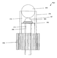
- FIG. 6 is an isometric view of the LED retrofit light source of FIG. 5 in another partially unassembled configuration, in which the inner rod is disposed within the outer tube and including a remote phosphor dome separate from the heat sink body;
- FIG. 7 is an isometric view of the LED retrofit light source of FIG. 6 in a further partially unassembled configuration, including the inner rod and the outer tube being disposed within the heat sink body and the remote phosphor dome still being separate from the heat sink body;
- FIG. 8 is an isometric view of the LED retrofit light source of FIG. 7 in an assembled configuration with the remote phosphor dome being coupled to the heat sink body;
- FIG. 9 is an isometric, exploded view of another exemplary embodiment of a LED retrofit light source in which a newly available, off-the-shelf, high-powered white LED package is incorporated therein;
- FIG. 10 is a side, view of the LED retrofit light source of FIG. 9 in which a portion of an outer tube of the light source is hidden, the light source including the white LED package, a spacer, and an optic;
- FIG. 11A is a partial, top view of the LED retrofit source of FIG. 10 illustrating a bottom portion of the white LED package;
- FIG. 11B is partial, top view of the LED retrofit light source of FIG. 10 illustrating a top portion of the spacer;
- FIG. 12 is partial, top view of the LED retrofit light source of FIG. 10 illustrating the bottom portion of the white LED package and the top portion of the spacer, with the white LED package and the spacer being mounted in a heat sink body, which can be metal;
- FIG. 13 is various isometric views of the LED retrofit light source of FIG. 10 in an assembled configuration
- FIG. 14 is a side, cross-sectional view of an otoscope having the LED retrofit light source of FIG. 8 or FIG. 13 installed therein;
- FIG. 15 is a side, cross-sectional view of the otoscope of FIG. 14 connected to an otoscope body.
- the present invention relates to devices in which a LED light source can be retrofitted, and methods of replacing current light sources with a LED light source as described herein.
- Light sources that can be replaced include existing miniature light bulbs. While the present description and figures primarily discuss the inventive light sources as being used in conjunction with an otoscope, a person skilled in the art will recognize that the inventive light sources disclosed herein, and methods related to the same, can be used in a variety of different instruments and tools across any number of industries. By way of non-limiting example, the inventive light sources, and methods related to the same, can be incorporated in other medical instruments and tools, such as diagnostic devices, ophthalmoscopes, anoscopes, vaginoscopes, and the like.
- inventive light sources, and methods related to the same can be used include household, business, and construction appliances, tools, and instruments, the automotive industry, such as for illuminating dashboards and for other interior and exterior lights, the aircraft industry, such as for panel illumination, the computer industry, the electronics industry, and any number of other industries in which miniature bulbs can be used as light sources.
- automotive industry such as for illuminating dashboards and for other interior and exterior lights
- aircraft industry such as for panel illumination
- the computer industry such as for panel illumination
- the electronics industry any number of other industries in which miniature bulbs can be used as light sources.
- devices and methods discussed herein are primarily discussed with respect to retrofitting an existing device, the disclosed devices and methods can also be used in conjunction with manufacturing new devices and systems in any number of industries.
- FIGS. 5-8 One embodiment of a LED lamp emitting white light for the replacement of tungsten-halogen lamps in otoscopes is shown in FIGS. 5-8 .
- This embodiment uses the concept of a remote phosphor conversion layer being disposed on top of a chip on board (COB).
- COB chip on board
- a light source 360 is shown in isometric view and includes an outer heat sink body 300 , an inner rod 310 , and an outer tube 320 .
- the outer tube 320 is a polycrystalline alumina/aluminum-oxynitride tube (PCA/AlON) tube.
- the heat sink 300 can be constructed out of a material having high thermal conductance such as aluminum or copper.
- the heat sink 300 can be plated with a material such as a gold or silver. Other materials having similar properties can also be used, including in place of, in conjunction with, or as a coating.
- the heat sink can be made of a polymer, such as a plastic, which can help make the cost of manufacturing inexpensive.
- a top face 301 of the heat sink 300 can be wire bonded to the heat sink 300 , and in such instances, a coating that is compatible with such wire bonding can also be included.
- a coating that is compatible with such wire bonding include, but are not limited to, a coating including gold, silver, or zinc.
- coating the heat sink 300 can protect against corrosion. Further, coating the heat sink 300 can allow for a desirable thermal interface between the light source 360 and an inside of an otoscope in which it will be installed, as illustrated, for example, in FIG. 14 , in which the light source 360 is incorporated into the otoscope 500 .
- the inner rod 310 can be used for electrical and thermal conductance.
- the inner rod 310 can constructed out of a material with high thermal conductance, such as metal, including metals like aluminum or copper. Any other number of materials that have or can be adapted to have high thermal conductance can also be used.
- the outer tube 320 can be plated with a material such as gold or silver for the reasons described above, and with other similar materials, as also described above.
- the outer tube 320 can be molded or extruded out of PCA and/or AlON, which are both readily available materials. Other materials can also be used to achieve the desired effect.
- an alternative to including the outer tube 320 includes anodizing the inner rod 310 .
- the anodization can be a thermal but not electrical conductor.
- the outer tube 320 or anodized inner rod 310 can serve as a lateral heat transfer enhancer(s) while providing complete electrical insulation.
- the inner rod 310 can be coupled to the outer tube 320 in any number of ways.
- the inner rod 310 can be press-fit inside the outer tube 320 using any number of physical forces.
- the inner rod 310 is press-fit tightly against the outer tube 320 to allow for good thermal transfer therebetween.
- an adhesive component can be used between the inner rod 310 and the outer tube 320 , such as a thermal epoxy.
- the thermal epoxy can be applied to the outsides of the inner rod 310 and/or the insides of the outer tube 320 so that air space between the two components can be minimized or eliminated when the inner rod 310 is disposed within the outer tube 320 .
- a sealing substance can be disposed between the inner rod 310 and the outer tube 320 after they are coupled together.
- a sub-assembly of the inner rod 310 and the outer tube 320 can be coupled to the heat sink 300 , for instance by press-fitting the sub-assembly into the heat sink 300 by way of a physical force.
- the sub-assembly can generally be referred to as a conductive material.
- the physical force can be applied in any number of ways.
- FIG. 6 there is shown an isometric view of the light source 360 in a partially un-assembled configuration.
- the sub-assembly of the inner rod 310 and the outer tube 320 , the heat sink 300 , a blue light-emitting die or chip (LED die) 340 , a wire bond 341 , and a remote phosphor dome 350 are illustrated.
- LED die blue light-emitting die or chip
- wire bond 341 a remote phosphor dome 350
- a COB approach is used to directly integrate the LED with the heat sink. This method can yield excellent heat extraction because the material interfaces between a bottom of the LED die 340 and the heat sink 300 are minimized.
- the LED die 340 can be mounted to the inner rod 310 in any number of ways using any number of substance.
- the LED die 340 can be bonded at a top surface of the inner rod 310 using epoxy die bonding or eutectic die bonding.
- the LED die 340 can also have a number of different properties.
- the LED 340 can have peak emissions between approximately 445 nanometers and approximately 475 nanometers. Examples of such dies include dies manufactured by Nichia, OSRAM Opto, and Cree.
- the LED die 340 can be chosen that has an anode or cathode, depending on the specific device being retrofitted, so that when the inner rod 310 makes contact with the battery electrical contact inside an otoscope or other device, the polarity is correct.
- an electrical contact can be made between a cathode of the LED die 340 and a cathode of the heat sink 300 .
- the heat sink 300 can serve as both a cathode and a cooling device.
- the heat sink 300 includes one or more radiating fins 302 that transfer heat from the LED die 340 to the otoscope's metal body, thereby resulting in an even greater cooling surface area.
- the top face 301 of the heat sink 300 can be where electrical contact between the cathode of the LED die 340 and the cathode of the heat sink 300 is made. This electrical contact can be bridged using the wire bond 341 .
- the wire bond 341 can be bonded from the cathode point of the LED die 340 over to the heat sink 300 .
- the heat sink 300 can be compatible with wire bonding, thereby serving as an excellent point of contact for the wire bond 341 .
- One way of achieving the excellent point of contact for the heat sink 300 can be by including a plating made of materials such as gold, silver, or zinc.
- FIG. 7 A better view of the completed wire bond can be seen in FIG. 7 .
- the remote phosphor dome 350 can be seen and will be explained in further detail below.
- FIG. 7 there is shown an isometric view of the light source 360 in another partially un-assembled configuration showing the inner rod 310 inserted inside of the outer tube 320 to form a sub-assembly, and the sub-assembly inserted into heat sink 300 .
- the remote phosphor dome 350 is shown as being removed from a top of the heat sink 300 , but when coupled together the dome 350 and the heat sink 300 with the sub-assembly disposed therein and the LED die 340 can form the fully assembled light source 360 .
- a portion or the entire surface of any of the LED die 340 , the wire bond 341 , the inner rod 310 , the outer tube 320 , and the heat sink 300 can be covered with one or more drops of silicone that can serve as index matching of refraction for the LED to enhance blue light extraction.
- the entire surface of each of the LED die 340 , the wire bond 341 , the inner rod 310 , the outer tube 320 , and the heat sink 300 is covered by at least one drop of silicone.
- the dome 350 can be coupled to the heat sink 300 after the silicone is placed on the various components of the light source 360 , and thus can be placed on top of the drop of silicone.
- the remote phosphor dome 350 can have a number of shapes and sizes, but in the illustrated embodiment the dome is hemispherical is shape to form a shell or dome layer.
- the phosphor dome 350 can made of clear plastics or silicone blended with a mix of phosphors to convert blue light from the light emitting diode into warm white light, which can have a high color rendering index (CRI), for instance, approximately greater than about 85.
- CRI color rendering index
- the warm color temperature typically required for the scope which can include a color temperature (CCT) from approximately 2700 K to approximately 3200 K, can be achieved by varying the ratio of commercially available red phosphors and YAG/Ce yellow phosphors manufactured for LED use.
- FIG. 8 there is shown an isometric view of the light source 360 in its fully assembled configuration.
- the remote phosphor dome or shell 350 can be seen installed on top.
- the dome 350 can be coupled to the heat sink 300 by way of male and female components associated with the dome 350 and the heat sink 300 , a snap-fit configuration, an interference-fit configuration, or any number of ways by which two components can be coupled.
- the completed LED retrofit using COB and remote phosphor can now be seen finished as light source 360 .
- the heat sink fins are shown in a spiraled configuration, rather than the straight configuration described with respect to the fins 302 described previously in FIG. 6 .
- the completed LED retrofit lamp or light source 360 can be installed inside an otoscope head, like the head 100 of FIG. 1 , replacing a tungsten-halogen bulb 26 . It can also be installed in a new otoscope, or other new or existing device.
- FIGS. 9-13 A second embodiment of a LED lamp emitting white light for the replacement of tungsten-halogen lamps in otoscopes is shown in FIGS. 9-13 .
- This embodiment use the concept of incorporating high-powered white LED packages into a light source. High-powered white LED packages are available off-the-shelf.
- FIG. 9 there is shown an isometric view of an embodiment of a light source 460 in a fully exploded configuration.
- This embodiment shares the following same components as the first embodiment of the invention: the heat sink 300 , the inner rod 310 , and the outer tube 320 .
- Each of these components can have properties similar to those described above for the components.
- the components can be coated and assembled in a similar manner.
- the main difference between the light source 460 and the light source 360 is that the light source 460 incorporates a high-powered white LED package 390 into the design. This white LED package is newly available from manufacturers such as Nichia, OSRAM Opto, and Cree.
- the white LED package 390 is a Nichia 119 .
- Advancements included in the present invention include a ceramic substrate 391 and new phosphor blends that yield a desirable CCT of approximately 2700 K to approximately 3200 K and a desirable CRI of approximately greater than about 85. These advancements allow for a very high lumen per watt rating, which in turn can yield a high power and light output efficiency.
- the white LED package 390 can be mounted on the face 311 of the inner rod 310 and on the heat sink 300 . Unlike the light source 360 , a wire bond is not used because the white LED package 390 has its anode and cathode connection points at a bottom of the ceramic substrate 391 via gold plated electrically conducted pads.
- a spacer 380 can be molded out of a high thermally conductive ceramic material such as PCA and/or AlON, or other high conductance electrically insulated material as desired.
- the spacer 380 can be placed between the heat sink 300 and the white LED package 390 .
- the material used to form or coat the spacer 380 should be an electric insulator but thermal conductor.
- the spacer 380 which as shown is a ring shape but can have any number of shapes depending on the other components with which it is used, can be thin to minimize the time it takes for the heat to extract down from the white LED package 390 and into the heat sink 300 and inner rod 310 .
- the integration between the white LED package 390 and the other components of the lamp are described below with respect to FIGS. 10-12 .
- a sleeve 370 can be designed to fit directly over an upper portion 303 of the heat sink 300 .
- The, the sleeve 370 can be disposed around at least a portion of the heat sink 300 and the sub-assembly formed by the inner rod 310 and the outer tube 320 disposed in the heat sink 300 .
- the sleeve 370 is tubular.
- the heat sink 300 can be configured to have the equivalent of the sleeve 370 integrally formed as part of the heat sink 300 .
- the sleeve 370 can be constructed out of a material with high thermal conductance, such as a metal. Any number of metals can be used, including, for example, aluminum or copper.
- the sleeve 370 can be plated with a conductive material, such as a metal. Any number of metals can be used as a plating, including, for example, gold or silver. Additionally, coating the sleeve 370 can protect against corrosion. Further, coating the sleeve 370 can allow for a desirable thermal interface between the light source 460 and an inside of an otoscope in which it will be installed.
- the sleeve 370 can be press-fit onto the upper portion 303 of the heat sink 300 , for example, by use of physical force.
- a number of different manners of exerting a physical force can be used to assemble the sleeve 370 and the heat sink 300 .
- the sleeve 370 is press-fit tightly against the upper portion 303 to allow for good thermal transfer therebetween.
- a thermal epoxy that is readily available can be applied to the inside walls of the tubular metal sleeve 370 so that it has no air space when pressed onto the upper part 303 of heat sink 300 .
- an adhesive component can be used between the sleeve 370 and the upper portion 303 , such as a thermal epoxy.
- the thermal epoxy can be applied to either or both of the conjoining surfaces of the sleeve 370 and the upper portion 303 so that air space between the two components can be minimized or eliminated when the sleeve 370 is coupled to the heat sink 300 .
- a sealing substance can be disposed between the sleeve 370 and the upper portion 303 of the heat sink 300 after they are coupled together.
- An optic 400 can be designed for each application to efficiently extract the light from the white LED package 390 .
- This optic 400 can be in the form of many different shapes such as spherical, convex, concave, etc. Additionally, some applications may require no lens at all.
- the optic 400 takes the form of a glass or optically clear plastic such as polycarbonate or acrylic. Any number of other materials which have similar properties of glass or optically clear plastic, i.e., that allows light to be emitted through it, can also be used.
- a diameter of the optic 400 can be closely matched to the inner diameter of sleeve 370 .
- FIG. 10 there is shown a side view of the light source 460 .
- the sleeve 370 has been partially hidden to make to easier to show the assembled state of features such as the white LED package 390 , the spacer 380 and the optic 400 .
- the spacer 380 can be seated directly under the white LED package 390 .
- an optically clear silicone or optically clear resin can be dispensed into a space 410 surrounding the white LED package 390 .
- This silicone or resin can serve as index matching of refraction for the white LED package 390 and into the optic 400 to enhance white light extraction, similar to the silicone as described with respect to the light source 360 .
- the optic 400 can be directly over the white LED package 390 .
- the silicone or resin filling the space 410 can act as an adhesive to hold the optic 400 permanently into place. Other adhesives or other mechanisms or ways used to couple two components together can also be used.
- the combination of the optic 400 and the sleeve 370 can work together to extract light from the white LED package 390 . This light can then be introduced into an entrance of optical fibers of a device, such as the optical fibers 38 of the otoscope 10 illustrated in FIG. 1 .
- FIGS. 11A and 11B there is shown a top view of the spacer 380 along with a bottom of the white LED package 390 .
- a Nichia 119 white LED package 390 is used because of its small overall dimensions, and further, because of the alignment and size of gold plated electrical contact pads 392 and 393 .
- the bottom of the white LED package 390 is shown, and the ceramic substrate 391 is visible as well.
- the cathode pad 392 provides electrical and thermal interface for the LED.
- the anode pad 393 provides electrical and thermal interface for the LED as well.
- the spacer 380 has its material shown in white and its voids shown in black.
- the two voids represent the area in which when the white LED package 390 is placed on top of the spacer 380 , the cathode and anodes of the white LED package 390 will be aligned with the cathode and anode voids of spacer 380 , as described more in detail in FIG. 12 .
- FIG. 12 there is shown a top view of the spacer 380 along with the bottom substrate 391 of the white LED package 390 and the top of the heat sink 300 .
- This view is intended to aid in understanding how the spacer 391 integrates with the heat sink 300 and white LED package 390 .
- the silicone dome of white LED package 390 has been removed.
- One exemplary procedure for assembling these components is as follows.
- the heat sink 300 , inner rod 310 , and outer tube 320 are assembled according to the procedure outlined with regards to the light source 360 .
- the spacer 380 which can be of approximately identical diameter to an outer diameter of the top face 301 of the heat sink 300 can be placed on top of the heat sink 300 .
- commercially available solder paste can be dispensed into the voids 381 and 382 of the spacer 380 .
- the cathode pad 381 and the anode pad 382 of the white LED package 380 are aligned to interface with the cathode void 381 and the anode void 382 on the spacer 380 .
- the entire assembly can then be placed in a heating source, such as a solder reflow oven or hot plate.
- the solder paste can be cured, thereby making a permanent bond between the white LED package 390 and the heat sink 300 and the inner rod 310 .
- This solder paste can act as both a bonding agent as well as a thermal and electrical transfer agent.
- the spacer 380 can be effectively “sandwiched” tightly between these aforementioned components, and therefore, can act as a good thermal interface.
- the cathode pad 381 can now be in contact with the heat sink 300 .
- the battery electrical contact inside the otoscope or other device can make contact with the cathode pad 381 .
- the anode pad 381 can now be in contact with the inner rod 310 .
- the LED retrofit or light source 460 when the LED retrofit or light source 460 is inserted into an otoscope or other device, the battery electrical contact inside the otoscope or other device can make contact with the anode pad 381 . Consequently, the LED retrofit will illuminate.
- This method of electrical and thermal contact can be modified for use with different devices so that the polarities are correctly matched between the LED and device. Also of note is that one or more inner rods and tubes can be needed to correctly isolate polarities, depending on device configuration.
- FIG. 13 various isometric views showing various angles of the light source 460 in its fully assembled configuration are illustrated.
- the optic 400 can be seen installed and sticking out of the top.
- the completed LED retrofit or light source 460 uses available, off-the-shelf high-powered white LED packages.
- the completed LED retrofit lamp or light source 460 can be installed inside an otoscope head, like the head 100 of FIG. 1 , replacing a tungsten-halogen bulb 26 . It can also be installed in a new otoscope, or other new or existing device.
- FIGS. 14 and 15 there is shown one exemplary embodiment of the light source 360 or the light source 460 being installed in an otoscope 500 .
- the otoscope is dissembled from an otoscope base or body 510 .
- the previous bulb for example the bulb 26 of FIG. 1 .
- the light source 360 or the light source 460 is then inserted into the same location. It can be desirable to have the light source 360 or the light source 460 fit tightly into the space previously occupied by the previous bulb to allow for good thermal contact, thereby allowing heat to be extracted away from the light source 360 or the light source 460 to further cool the light source.
- the otoscope 500 can then be reassembled by connecting the otoscope 500 to the base or body 510 and the otoscope 500 is then ready for use.
- the electrical connectivity of the lamp inside of the otoscope 500 is better explained with reference to FIG. 15 .
- the otoscope 500 contains an anode and cathode connection that can be powered by a rechargeable battery or can be plugged into a wall socket. This connection can be brought from the power source and then can be wired to a switch and then to a pin 511 and otoscope body 510 .
- the otoscope body 510 acts as the cathode and the pin 511 acts as the anode.
- the LED retrofit light source 360 or the light source 460 has electrical connections as described above and as follows: the cathode connection can be via the entire outer body, the heat sink 300 , and the sleeve 370 and the anode connection can be via the inner pin 310 .
- the cathode electrical connection can be made by having the otoscope 500 and the otoscope body 510 make physical contact with the heat sink 300 and the sleeve 370 of the light source 360 or the light source 460 .
- the anode electrical connection can be made by having including a vertical spring pin 511 in the otoscope body.
- Twisting the otoscope head 500 onto the otoscope body 510 can allow the pin 511 to make physical contact with the pin 310 of the light source 360 or the light source 460 .
- the electrical connections are complete and require no additional wiring for on/off operation or dimming operation, which can all be controlled by one or more switches of an otoscope. If the light source 360 or the light source 460 are not designed to have the correct polarities (anode and cathode positions) as these embodiments do, than additional modification, for example wiring, an electronic converter, and/or switching the battery, would be required for proper use of the otoscope.
- additional resistance can be added to the light source 360 or the light source 460 , for example, by adding a resistor, resistor wire, or other components that can provide resistance as desired.
- any component of the light sources 360 , 460 , and the light sources 360 , 460 themselves, can be configured to have a variety of shapes, sizes, and configurations depending at least in part on the size of the instrument in which the light sources will be disposed and the shapes, sizes, and configurations of the other components of the light sources.
- the light source has a width in the range of approximately 6 millimeters to approximately 9 millimeters and a length of approximately 15 millimeters to approximately 21 millimeters
- any number of materials can be used to form any of the components of the light sources 360 , 460 .
- the materials suggested are merely examples, and other materials having similar properties and characteristics or that are used with light sources, or components in which light sources are used, such as otoscopes. Materials can be adapted to including desirable properties, for instance by coating them or modifying them in other manners.
- LED packages are described as having a particular color, e.g., white, a particular range of CCT, e.g., approximately 2700 K to approximately 3200 K, or a particular CRI, e.g., approximately equal to or greater than about 85, a person skilled in the art will recognize that other colors can also be achieved, in conjunction with or in place of white light, a particular CCT, and/or a particular CRI.
- manufacturing processes are discussed in a particular order, a person skilled in the art will recognize that other orders can also be used while still keeping within the spirit of the invention.
- the LED retrofit light sources can be used to replace tungsten-halogen lamps, as well as other lamps, used in commercially available products such as otoscopes.
- the remote phosphor shell can warm CCT and CRI can be tailored to specific market needs.
- the light sources of the present disclosure can be at least four times more efficient than tungsten-halogen lamps, as well as other lamps, which in turn can lead to longer life expectancies and shorter battery recharge times.
- the life-expectancy of the light sources disclosed herein can be approximately 50,000 hours.
- the light sources disclosed herein can contain no filament, and further, can be unbreakable.
- the plastic remote phosphor shells can be manufactured very inexpensively.
- such jackets can promote lateral heat transfer enhancement, which in turn can reduce LED temperature as well as provide electrical insulation.
- the fin(s) can be located in the outer conductor assembly, thereby promoting additional cooling.
- Use of small, white LED packages in conjunction with spacers made of ceramic or other high conductance, electrically insulating materials can be an excellent way to effective transfer heat into the heat sink, and thus into the otoscope or other device in which the teachings of the present invention are incorporated.
- Embodiments that use a spacer, or a spacer made of another material but configured to have the same properties of ceramic that are effective for use in conjunction with the teachings herein, is a new way to interface an LED in a small space with a heat sink, and can be an improvement over use of a circuit board material.
Landscapes
- Health & Medical Sciences (AREA)
- Life Sciences & Earth Sciences (AREA)
- Surgery (AREA)
- Engineering & Computer Science (AREA)
- Physics & Mathematics (AREA)
- Optics & Photonics (AREA)
- Biomedical Technology (AREA)
- Molecular Biology (AREA)
- Pathology (AREA)
- Nuclear Medicine, Radiotherapy & Molecular Imaging (AREA)
- Biophysics (AREA)
- Heart & Thoracic Surgery (AREA)
- Medical Informatics (AREA)
- Radiology & Medical Imaging (AREA)
- Animal Behavior & Ethology (AREA)
- General Health & Medical Sciences (AREA)
- Public Health (AREA)
- Veterinary Medicine (AREA)
- Microelectronics & Electronic Packaging (AREA)
- General Engineering & Computer Science (AREA)
- Arrangement Of Elements, Cooling, Sealing, Or The Like Of Lighting Devices (AREA)
- Non-Portable Lighting Devices Or Systems Thereof (AREA)
Abstract
Description
Claims (19)
Priority Applications (1)
| Application Number | Priority Date | Filing Date | Title |
|---|---|---|---|
| US12/778,264 US8106569B2 (en) | 2009-05-12 | 2010-05-12 | LED retrofit for miniature bulbs |
Applications Claiming Priority (2)
| Application Number | Priority Date | Filing Date | Title |
|---|---|---|---|
| US17748709P | 2009-05-12 | 2009-05-12 | |
| US12/778,264 US8106569B2 (en) | 2009-05-12 | 2010-05-12 | LED retrofit for miniature bulbs |
Publications (2)
| Publication Number | Publication Date |
|---|---|
| US20100314986A1 US20100314986A1 (en) | 2010-12-16 |
| US8106569B2 true US8106569B2 (en) | 2012-01-31 |
Family
ID=43085553
Family Applications (1)
| Application Number | Title | Priority Date | Filing Date |
|---|---|---|---|
| US12/778,264 Expired - Fee Related US8106569B2 (en) | 2009-05-12 | 2010-05-12 | LED retrofit for miniature bulbs |
Country Status (2)
| Country | Link |
|---|---|
| US (1) | US8106569B2 (en) |
| WO (1) | WO2010132517A2 (en) |
Cited By (5)
| Publication number | Priority date | Publication date | Assignee | Title |
|---|---|---|---|---|
| US20110170301A1 (en) * | 2007-02-14 | 2011-07-14 | Russell George Villard | Thermal Transfer in Solid State Light Emitting Apparatus and Methods of Manufacturing |
| US20140085893A1 (en) * | 2012-09-24 | 2014-03-27 | Itzhak Sapir | Thermally-Managed Electronic Device |
| US20150282701A1 (en) * | 2014-04-04 | 2015-10-08 | Boston Scientific Scimed, Inc. | Medical system and related methods for diagnosis and treatment |
| US12104771B2 (en) | 2023-01-27 | 2024-10-01 | Wangs Alliance Corporation | Small aperture light emitting diode (“LED”) lighting |
| US12228274B2 (en) * | 2023-07-18 | 2025-02-18 | Wangs Alliance Corporation | Low glare fixture |
Families Citing this family (19)
| Publication number | Priority date | Publication date | Assignee | Title |
|---|---|---|---|---|
| JP5489827B2 (en) * | 2010-04-06 | 2014-05-14 | オリンパス株式会社 | Optical device |
| US8786210B2 (en) | 2010-06-30 | 2014-07-22 | Welch Allyn, Inc. | Drive circuit for light emitting diode |
| US8459844B2 (en) | 2010-07-01 | 2013-06-11 | Welch Allyn, Inc. | Replacement light assembly |
| US20120052460A1 (en) * | 2010-08-30 | 2012-03-01 | Dentalez, Inc. | Dental handpiece swivel coupling with an autoclavable illuminator assembly |
| US9127816B2 (en) * | 2011-01-19 | 2015-09-08 | GE Lighting Solutions, LLC | LED light engine/heat sink assembly |
| JP5540036B2 (en) * | 2012-03-26 | 2014-07-02 | 富士フイルム株式会社 | Endoscope |
| US8882293B2 (en) | 2012-11-06 | 2014-11-11 | Hinkley Lightings, Inc. | LED light apparatus |
| DE102013201808A1 (en) * | 2013-02-05 | 2014-08-07 | Richard Wolf Gmbh | LED lighting module |
| JP6411731B2 (en) * | 2013-12-04 | 2018-10-24 | オリンパス株式会社 | Imaging apparatus and endoscope |
| US9472108B2 (en) * | 2014-03-17 | 2016-10-18 | Honeywell International Inc. | Updating an airfield lighting system with an LED light source |
| HRP20200833T1 (en) * | 2014-12-22 | 2020-08-07 | Mag Instrument, Inc. | Improved efficiency lighting apparatus with led directly mounted to a heatsink |
| DE102015212169A1 (en) * | 2015-06-30 | 2017-01-05 | Osram Gmbh | Circuit carrier for an electronic circuit and method for producing such a circuit carrier |
| DE102015212177A1 (en) * | 2015-06-30 | 2017-01-05 | Osram Gmbh | Circuit carrier for an electronic circuit and method for producing such a circuit carrier |
| US20170067622A1 (en) * | 2015-09-08 | 2017-03-09 | Everlight Electronics Co., Ltd. | Monolithic Base Of LED Lighting Module And Lamp Having The Same |
| CN207279337U (en) * | 2017-10-12 | 2018-04-27 | 维必玛电器(汕头)有限公司 | Mineral salt light bulb |
| US10443834B1 (en) | 2018-06-06 | 2019-10-15 | Mag Instrument, Inc. | LED flashlight with improved heat sink |
| US10605412B1 (en) | 2018-11-16 | 2020-03-31 | Emeryallen, Llc | Miniature integrated omnidirectional LED bulb |
| WO2020217669A1 (en) * | 2019-04-24 | 2020-10-29 | パナソニックIpマネジメント株式会社 | Light emitting device; and medical system, electronic apparatus, and inspection method using same |
| ES1255295Y (en) * | 2020-07-28 | 2021-01-19 | Mingo Francisco Javier Garcia | VENOUS TRANSILUMINATOR |
Citations (13)
| Publication number | Priority date | Publication date | Assignee | Title |
|---|---|---|---|---|
| US3698387A (en) | 1969-10-07 | 1972-10-17 | Welch Allyn Inc | Otoscope construction |
| US5998925A (en) | 1996-07-29 | 1999-12-07 | Nichia Kagaku Kogyo Kabushiki Kaisha | Light emitting device having a nitride compound semiconductor and a phosphor containing a garnet fluorescent material |
| US20040079957A1 (en) | 2002-09-04 | 2004-04-29 | Andrews Peter Scott | Power surface mount light emitting die package |
| US20040186352A1 (en) | 2003-03-20 | 2004-09-23 | Welch Allyn, Inc. | Illumination system for medical diagnostic instrument |
| JP2005251588A (en) | 2004-03-04 | 2005-09-15 | Hamamatsu Photonics Kk | Light irradiation device |
| US20060024638A1 (en) | 2004-07-02 | 2006-02-02 | Kenneth Rosenblood | Curing light |
| US20070010157A1 (en) * | 1999-04-22 | 2007-01-11 | Jorg-Erich Sorg | LED light source with lens |
| US7276025B2 (en) | 2003-03-20 | 2007-10-02 | Welch Allyn, Inc. | Electrical adapter for medical diagnostic instruments using LEDs as illumination sources |
| US20080093962A1 (en) * | 2004-09-15 | 2008-04-24 | Seoul Semiconductor Co., Ltd. | Luminous Device with Heat Pipe and Method of Manufacturing Heat Pipe Lead for Luminous Device |
| US20080273329A1 (en) | 2004-06-15 | 2008-11-06 | Belek Ronald E | High Power Led Electro-Optic Assembly |
| US7491000B2 (en) * | 2005-04-27 | 2009-02-17 | Kyocera Corporation | Base structure for light emitting device and light emitting device using the same |
| US20090323346A1 (en) * | 2008-06-25 | 2009-12-31 | Foxconn Technology Co., Ltd. | Light emitting diode structure |
| US20100171403A1 (en) * | 2009-01-05 | 2010-07-08 | Fu Zhun Precision Industry (Shen Zhen) Co., Ltd. | Led lamp |
-
2010
- 2010-05-12 WO PCT/US2010/034469 patent/WO2010132517A2/en not_active Ceased
- 2010-05-12 US US12/778,264 patent/US8106569B2/en not_active Expired - Fee Related
Patent Citations (16)
| Publication number | Priority date | Publication date | Assignee | Title |
|---|---|---|---|---|
| US3698387A (en) | 1969-10-07 | 1972-10-17 | Welch Allyn Inc | Otoscope construction |
| US5998925A (en) | 1996-07-29 | 1999-12-07 | Nichia Kagaku Kogyo Kabushiki Kaisha | Light emitting device having a nitride compound semiconductor and a phosphor containing a garnet fluorescent material |
| US6069440A (en) | 1996-07-29 | 2000-05-30 | Nichia Kagaku Kogyo Kabushiki Kaisha | Light emitting device having a nitride compound semiconductor and a phosphor containing a garnet fluorescent material |
| US20070010157A1 (en) * | 1999-04-22 | 2007-01-11 | Jorg-Erich Sorg | LED light source with lens |
| US20040079957A1 (en) | 2002-09-04 | 2004-04-29 | Andrews Peter Scott | Power surface mount light emitting die package |
| US7276025B2 (en) | 2003-03-20 | 2007-10-02 | Welch Allyn, Inc. | Electrical adapter for medical diagnostic instruments using LEDs as illumination sources |
| US20040186352A1 (en) | 2003-03-20 | 2004-09-23 | Welch Allyn, Inc. | Illumination system for medical diagnostic instrument |
| US7458934B2 (en) | 2003-03-20 | 2008-12-02 | Welch Allyn, Inc. | Electrical adapter for medical diagnostic instruments using replaceable LEDs as illumination sources |
| JP2005251588A (en) | 2004-03-04 | 2005-09-15 | Hamamatsu Photonics Kk | Light irradiation device |
| US20080273329A1 (en) | 2004-06-15 | 2008-11-06 | Belek Ronald E | High Power Led Electro-Optic Assembly |
| US20060024638A1 (en) | 2004-07-02 | 2006-02-02 | Kenneth Rosenblood | Curing light |
| JP2008505454A (en) | 2004-07-02 | 2008-02-21 | ディスカス デンタル インプレッションズ インコーポレーテッド | Curing light with reflector |
| US20080093962A1 (en) * | 2004-09-15 | 2008-04-24 | Seoul Semiconductor Co., Ltd. | Luminous Device with Heat Pipe and Method of Manufacturing Heat Pipe Lead for Luminous Device |
| US7491000B2 (en) * | 2005-04-27 | 2009-02-17 | Kyocera Corporation | Base structure for light emitting device and light emitting device using the same |
| US20090323346A1 (en) * | 2008-06-25 | 2009-12-31 | Foxconn Technology Co., Ltd. | Light emitting diode structure |
| US20100171403A1 (en) * | 2009-01-05 | 2010-07-08 | Fu Zhun Precision Industry (Shen Zhen) Co., Ltd. | Led lamp |
Non-Patent Citations (1)
| Title |
|---|
| International Search Report and Written Opinion for application No. PCT/US2010/034469 mailed Dec. 27, 2010, 11 pages. |
Cited By (9)
| Publication number | Priority date | Publication date | Assignee | Title |
|---|---|---|---|---|
| US20110170301A1 (en) * | 2007-02-14 | 2011-07-14 | Russell George Villard | Thermal Transfer in Solid State Light Emitting Apparatus and Methods of Manufacturing |
| US8408749B2 (en) * | 2007-02-14 | 2013-04-02 | Cree, Inc. | Thermal transfer in solid state light emitting apparatus and methods of manufacturing |
| US20140085893A1 (en) * | 2012-09-24 | 2014-03-27 | Itzhak Sapir | Thermally-Managed Electronic Device |
| US20150282701A1 (en) * | 2014-04-04 | 2015-10-08 | Boston Scientific Scimed, Inc. | Medical system and related methods for diagnosis and treatment |
| US9949627B2 (en) * | 2014-04-04 | 2018-04-24 | Boston Scientific Scimed, Inc. | Medical system and related methods for diagnosis and treatment |
| US12104771B2 (en) | 2023-01-27 | 2024-10-01 | Wangs Alliance Corporation | Small aperture light emitting diode (“LED”) lighting |
| US12111040B2 (en) | 2023-01-27 | 2024-10-08 | Wangs Alliance Corporation | Small aperture light emitting diode LED lighting |
| US12320503B2 (en) | 2023-01-27 | 2025-06-03 | Wangs Alliance Corporation | Small aperture light emitting diode LED lighting |
| US12228274B2 (en) * | 2023-07-18 | 2025-02-18 | Wangs Alliance Corporation | Low glare fixture |
Also Published As
| Publication number | Publication date |
|---|---|
| US20100314986A1 (en) | 2010-12-16 |
| WO2010132517A3 (en) | 2011-03-03 |
| WO2010132517A2 (en) | 2010-11-18 |
Similar Documents
| Publication | Publication Date | Title |
|---|---|---|
| US8106569B2 (en) | LED retrofit for miniature bulbs | |
| US8752984B2 (en) | Glass LED light bulbs | |
| US8702257B2 (en) | Plastic LED bulb | |
| US8853921B2 (en) | Heat removal design for LED bulbs | |
| US20100001662A1 (en) | Led candelabra fixture and lamp | |
| CN111623253A (en) | LED filament lamps with V-shaped geometry | |
| EP3208514A1 (en) | Light bulb using led filament | |
| JPWO2014010141A1 (en) | Light bulb shaped lamp and lighting device | |
| CN109595480B (en) | CFL pins with a string of light engines | |
| GB2507386A (en) | LED light bulb and holder | |
| US9995437B2 (en) | LED bulb | |
| US20120043885A1 (en) | Led lamp with circling led modules and encapsulation | |
| CN106523942A (en) | Heatsink with integrated electrical and base contacts | |
| US8882306B2 (en) | Lighting device | |
| US11796163B2 (en) | Light emitting device having improved illumination and manufacturing flexibility | |
| TW201604481A (en) | Light-emitting diode light bulb | |
| WO2016156057A1 (en) | Lighting device with improved thermal performancespec | |
| JP5948666B2 (en) | Illumination light source and illumination device | |
| US20120262059A1 (en) | Lamp having a variable substrate as a base for a light source | |
| TWM457835U (en) | Lighting tube having two light-emitting surfaces | |
| CN102620156A (en) | lamps | |
| CN203404759U (en) | Heat radiation structure of LED lamp | |
| CN208546762U (en) | A kind of single end LED light source | |
| EP2312197A1 (en) | Illumination device | |
| CN204284996U (en) | LED and corresponding lighting device thereof |
Legal Events
| Date | Code | Title | Description |
|---|---|---|---|
| AS | Assignment |
Owner name: REMPHOS TECHNOLOGIES LLC, MASSACHUSETTS Free format text: ASSIGNMENT OF ASSIGNORS INTEREST;ASSIGNOR:GERSHAW, DAVID;REEL/FRAME:024732/0799 Effective date: 20100712 |
|
| ZAAA | Notice of allowance and fees due |
Free format text: ORIGINAL CODE: NOA |
|
| ZAAB | Notice of allowance mailed |
Free format text: ORIGINAL CODE: MN/=. |
|
| STCF | Information on status: patent grant |
Free format text: PATENTED CASE |
|
| CC | Certificate of correction | ||
| AS | Assignment |
Owner name: REMPHOS TECHNOLOGIES LLC, MASSACHUSETTS Free format text: ASSIGNMENT OF ASSIGNORS INTEREST;ASSIGNOR:GERSHAW, DAVID;REEL/FRAME:033794/0190 Effective date: 20140715 |
|
| FPAY | Fee payment |
Year of fee payment: 4 |
|
| FEPP | Fee payment procedure |
Free format text: PAYOR NUMBER ASSIGNED (ORIGINAL EVENT CODE: ASPN); ENTITY STATUS OF PATENT OWNER: SMALL ENTITY |
|
| AS | Assignment |
Owner name: BLACKBIRD TECH LLC, MASSACHUSETTS Free format text: ASSIGNMENT OF ASSIGNORS INTEREST;ASSIGNOR:GERSHAW, DAVID;REEL/FRAME:041206/0288 Effective date: 20170208 |
|
| AS | Assignment |
Owner name: GERSHAW, DAVID, MASSACHUSETTS Free format text: ASSIGNMENT OF ASSIGNORS INTEREST;ASSIGNOR:REMPHOS TECHNOLOGIES LLC;REEL/FRAME:041229/0433 Effective date: 20170125 |
|
| FEPP | Fee payment procedure |
Free format text: MAINTENANCE FEE REMINDER MAILED (ORIGINAL EVENT CODE: REM.); ENTITY STATUS OF PATENT OWNER: SMALL ENTITY |
|
| FEPP | Fee payment procedure |
Free format text: 7.5 YR SURCHARGE - LATE PMT W/IN 6 MO, SMALL ENTITY (ORIGINAL EVENT CODE: M2555); ENTITY STATUS OF PATENT OWNER: SMALL ENTITY |
|
| MAFP | Maintenance fee payment |
Free format text: PAYMENT OF MAINTENANCE FEE, 8TH YR, SMALL ENTITY (ORIGINAL EVENT CODE: M2552); ENTITY STATUS OF PATENT OWNER: SMALL ENTITY Year of fee payment: 8 |
|
| AS | Assignment |
Owner name: SARTORI, ELISA, MASSACHUSETTS Free format text: ASSIGNMENT F/B/O CREDITORS OF BLACKBIRD TECH LLC;ASSIGNOR:BLACKBIRD TECH LLC;REEL/FRAME:063805/0261 Effective date: 20230118 |
|
| FEPP | Fee payment procedure |
Free format text: MAINTENANCE FEE REMINDER MAILED (ORIGINAL EVENT CODE: REM.); ENTITY STATUS OF PATENT OWNER: SMALL ENTITY |
|
| LAPS | Lapse for failure to pay maintenance fees |
Free format text: PATENT EXPIRED FOR FAILURE TO PAY MAINTENANCE FEES (ORIGINAL EVENT CODE: EXP.); ENTITY STATUS OF PATENT OWNER: SMALL ENTITY |
|
| STCH | Information on status: patent discontinuation |
Free format text: PATENT EXPIRED DUE TO NONPAYMENT OF MAINTENANCE FEES UNDER 37 CFR 1.362 |
|
| FP | Lapsed due to failure to pay maintenance fee |
Effective date: 20240131 |