US8103474B2 - Debug system - Google Patents
Debug system Download PDFInfo
- Publication number
- US8103474B2 US8103474B2 US12/306,532 US30653207A US8103474B2 US 8103474 B2 US8103474 B2 US 8103474B2 US 30653207 A US30653207 A US 30653207A US 8103474 B2 US8103474 B2 US 8103474B2
- Authority
- US
- United States
- Prior art keywords
- command
- microcomputer
- equipment
- debugged
- section
- Prior art date
- Legal status (The legal status is an assumption and is not a legal conclusion. Google has not performed a legal analysis and makes no representation as to the accuracy of the status listed.)
- Active, expires
Links
Images


Classifications
-
- G—PHYSICS
- G06—COMPUTING OR CALCULATING; COUNTING
- G06F—ELECTRIC DIGITAL DATA PROCESSING
- G06F11/00—Error detection; Error correction; Monitoring
- G06F11/22—Detection or location of defective computer hardware by testing during standby operation or during idle time, e.g. start-up testing
- G06F11/26—Functional testing
- G06F11/273—Tester hardware, i.e. output processing circuits
- G06F11/2733—Test interface between tester and unit under test
-
- G—PHYSICS
- G06—COMPUTING OR CALCULATING; COUNTING
- G06F—ELECTRIC DIGITAL DATA PROCESSING
- G06F11/00—Error detection; Error correction; Monitoring
- G06F11/36—Prevention of errors by analysis, debugging or testing of software
- G06F11/362—Debugging of software
- G06F11/3648—Debugging of software using additional hardware
Definitions
- the present invention relates to a debug system suitable for a use for carving out equipment diagnosis by setting equipment to be debugged such as an onboard information appliance before factory shipment in a specific operation environment.
- a microcomputer working as the control center of the onboard information equipment is often connected to a PC (Personal Computer) serving as a diagnostic apparatus via a serial communication channel (serial communication interface unit) to inform the outside of the internal state of the microcomputer.
- PC Personal Computer
- the microcomputer receives a command from the PC, and carries out operation in accordance with the command. For example, when the input command intends a “memory dump”, the microcomputer outputs its dump list to the PC. Program developers analyze the dump list they get using the memory dump function, and carry out debug and the like of the program to develop the program and check its operation.
- the foregoing memory dump function is sometimes used for checking on a mass production line after mass production following the program development. For example, it sometimes occurs that the operation environment of the microcomputer should be set in a specific operation mode (called “check mode” from now on) that the microcomputer does not use normally, such as disabling a display command to check the onboard information equipment to which a display monitor is not yet connected.
- check mode a specific operation mode
- the microcomputer does not use normally, such as disabling a display command to check the onboard information equipment to which a display monitor is not yet connected.
- CHECK a command for switching to the check mode from the PC
- the present invention is implemented to solve the foregoing problems. Therefore it is an object of the present invention to provide a debug system capable of changing, when setting the microcomputer, which works as the control center of the equipment to be debugged such as the onboard information equipment, in the operation environment the microcomputer does not use normally, the operation mode easily by inputting a command using a jig with a simple structure.
- a debug system in accordance with the present invention includes: equipment to be debugged, which is controlled by a microcomputer; and a command return jig connected to the equipment to be debugged via a communication interface unit, for receiving a specific command generated and output by the microcomputer via the communication interface unit, and for outputting the specific command by return to the equipment to be debugged, wherein the equipment to be debugged switches, when receiving the specific command from the command return jig, the microcomputer to set the microcomputer in an operation environment the microcomputer does not use normally.
- the jig with a simple structure is used to set the microcomputer, which works as the control center of the equipment to be debugged such as onboard information equipment, in the operation environment the microcomputer does not use normally. This makes it possible to change the operation mode easily by inputting the command.
- FIG. 1 is a block diagram showing a configuration example of a debug system of an embodiment 1 in accordance with the present invention
- FIG. 2 is a block diagram showing an internal configuration of a microcomputer shown in FIG. 1 with its functions being developed;
- FIG. 3 is a flowchart shown to explain the operation of the debug system of the embodiment 1 in accordance with the present invention
- FIG. 4 is a block diagram showing a configuration example of a debug system of an embodiment 2 in accordance with the present invention.
- FIG. 5 is a flowchart shown to explain the operation of the debug system of the embodiment 2 in accordance with the present invention.
- FIG. 1 is a block diagram showing a configuration example of a debug system of an embodiment 1 in accordance with the present invention.
- onboard information equipment 10 As equipment to be debugged, onboard information equipment 10 is illustrated here.
- the onboard information equipment 10 shown here comprises a microcomputer 11 working as a control center; a communication interface unit 12 connected as a connection interface with an external connection device; and a memory 13 for storing data passing through the processing by the microcomputer 11 .
- a command return jig 20 is shown here as an example of the external connection device.
- the command return jig 20 is attached to the onboard information equipment 10 via a connector 15 to return the command output from the onboard information equipment 10 to the onboard information equipment 10 via command transfer lines 101 and 102 .
- the command return jig 20 can be a hardware tool having a simple circuit configuration for returning the command only via a driver circuit not shown inserted between the command transfer line 101 and the command transfer line 102 .
- the onboard information equipment 10 and the command return jig 20 are connected via connectors 15 and 16 mounted on them, respectively.
- the onboard information equipment 10 (microcomputer 11 ) and the command return jig 20 are connected via a serial data transfer path (command transfer lines 101 and 102 ).
- the communication interface unit 12 is a voltage level converter for matching, when the onboard information equipment 10 performs communication with the external connection equipment, the voltage level of the communication signal between the onboard information equipment 10 and the external connection device.
- FIG. 2 is a block diagram showing an internal configuration of the microcomputer 11 working as the control center of the onboard information equipment 10 shown in FIG. 1 with its functions being developed.
- the configuration of the microcomputer 11 are roughly divided, in accordance with its functions, into a command input acquiring section 111 , a command deciding section 112 , a function executing section 113 , an output section 114 , a time watching section 115 and a command output section 116 .
- the command input acquiring section 111 has functions of acquiring a command the command return jig 20 returns and transmits, and of outputting it to the command deciding section 112 .
- the command deciding section 112 has functions of deciding the content of the command input and acquired to control the function executing section 113 .
- the function executing section 113 is a program executing means for executing prescribed functions in accordance with the content decided by the command deciding section 112 . For example, if the command requires the memory dump, it acquires the contents of the memory 13 from it (memory reading section 1130 ). In this case, the output of the function executing section 113 (a dump list, for example) is supplied to the communication interface unit 12 via the data output section 114 for outputting to the external connection device such as a PC, and via the input/output port 14 . Thus, if the switching is made to set the operation environment the microcomputer 11 does not use normally, the function executing section 113 operates as a first diagnostic function executing section described in claim 4 for executing equipment diagnosis in accordance with the specific operation environment based on the specific command.
- the time watching section 115 has functions of measuring time for watching the designated time under the control of the microcomputer 11 , and of controlling the command output section 116 .
- the command output section 116 has functions of outputting, instead of the output of the function executing section 113 , the same command as a command input from the outside of the onboard information equipment 10 during the time measured by the time watching section 115 , one minute, for example.
- FIG. 3 is a flowchart shown to explain the operation of the debug system of the embodiment 1 in accordance with the present invention.
- FIG. 3 the operation of the embodiment 1 in accordance with the present invention shown in FIG. 1 and FIG. 2 will now be described in detail.
- the command return jig 20 is attached to the exclusive connector 15 in advance.
- the microcomputer 11 After starting the onboard information equipment 10 , the microcomputer 11 initializes the serial port 14 for debugging, first, so as to set the microcomputer 11 at a state capable of communicating with the external connection device (the command return jig 20 , here) (step ST 301 ).
- the microcomputer 11 After the initialization, the microcomputer 11 starts the timer of the time watching section 115 to wait for a certain time after starting the command for setting the microcomputer 11 itself at the check mode (step ST 302 ). Subsequently, using the command output section 116 , the microcomputer 11 outputs the command “check” for switching the microcomputer 11 to the check mode via the output section 114 , the serial port 14 and the communication interface unit 12 (step ST 303 ).
- the microcomputer 11 After outputting the command “check”, the microcomputer 11 waits for the command, which will be output and returned from the command return jig 20 and then input, for the designated time measured by the time watching section 115 , for one minute, for example (steps ST 304 and ST 305 ).
- the command “check” output at step ST 303 is acquired by the command input acquiring section 111 within one minute for returning via the communication interface 12 and the serial port 14 of the onboard information equipment 10 .
- the command deciding section 112 makes a decision as to whether it is a check mode switching command “check” or not (step ST 306 ). If it is the check mode switching command (“Yes” at step ST 306 ), the function executing section 113 switches the operation mode of the microcomputer 11 to the check mode to establish the specific operation environment (step ST 307 ).
- the embodiment 1 in accordance with the present invention it is possible to switch and set the equipment to be debugged such as the onboard information equipment 10 in the operation environment the microcomputer 11 does not use normally (check mode, here) by only attaching the command return jig 20 with a simple structure as the external connection device without using comparatively large-scale expensive equipment such as a PC.
- the microcomputer 11 does not use normally, it is conceivable, for example, to ignore a display command, to extend the time period of activating under special conditions, to turn on a lamp if a particular function is executed when the command return jig 20 is attached, and to disable a certain monitoring function.
- the embodiment 1 can be effectively applied to the equipment to be debugged before the factory shipment such as that to which a display monitor is not yet connected, for example.
- such a configuration is also possible which has lamps connected to the onboard information equipment 10 , and turns on a lamp when receiving a specific command output and returned from the command return jig 20 within one minute the time watching section 115 monitors, thereby displaying that the microcomputer is switched to and set in the operation environment the microcomputer 11 does not use normally.
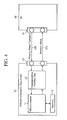
- FIG. 4 is a block diagram showing a configuration example of a debug system of an embodiment 2 in accordance with the present invention.
- the embodiment 2 differs from the embodiment 1 shown in FIG. 1 in that a PC 30 working as a diagnostic apparatus is connected to the onboard information equipment 10 instead of the command return jig 20 .
- the PC 30 can not only switch and set the microcomputer 11 serving as the control center of the onboard information equipment 10 in the specific operation environment the microcomputer 11 does not use normally, but also input a debug command such as a memory dump and diagnostic command, and obtain the results.
- the function executing section 113 shown in FIG. 2 it differs here in that it operates as a second function executing section described in claim 5 .
- the function executing section 113 can execute not only the specific command (check mode switching command “check”) output from the PC 30 connected via the communication interface unit 12 , but also the diagnostic command such as a debug command independently of the waiting within the designated time period. Its details will be described later.
- FIG. 5 is a flowchart shown to explain the operation of the debug system of the embodiment 2 in accordance with the present invention.
- the microcomputer 11 After the onboard information equipment 10 is switched on and started, the microcomputer 11 initializes the serial port 14 for communicating in the same manner as in the embodiment 1, first, so as to set the microcomputer 11 at a state capable of communicating with the external connection device (the PC 30 connected as the diagnostic apparatus, here) (step ST 301 ).
- the microcomputer 11 After the initialization, the microcomputer 11 starts the timer of the time watching section 115 to wait for a certain time after starting the command for setting the microcomputer 11 itself at the check mode (step ST 302 ). Subsequently, using the command output section 116 , the microcomputer 11 outputs the command “check” for switching the microcomputer 11 to the check mode on the mass production line via the output section 114 , the serial port 14 and the communication interface unit 12 (step ST 303 ).
- the microcomputer 11 After outputting the command “check”, the microcomputer 11 waits for the command, which will be input from the PC 30 , for the designated time measured by the time watching section 115 , for one minute, for example (steps ST 304 and ST 305 ).
- the PC 30 receives from the onboard information equipment 10 the specific command “check” for switching to the check mode, it can ignore it in the processing. Alternatively, the PC 30 can notify that the onboard information equipment 10 is started by receiving the specific command “check”.
- step ST 306 “Yes” When a certain command is input from the PC 30 within one minute after the onboard information equipment 10 is started, and the content of the command is the specific command “check” (step ST 306 “Yes”); the onboard information equipment 10 is switched to the specific operation environment (check mode) the microcomputer 11 does not use normally (step ST 307 ). In contrast, unless the input command is the specific command “check” (step ST 306 “No”), the microcomputer 11 makes a decision as to whether it is another command or not (step ST 308 ).
- the function executing section 113 carries out the processing corresponding to that command (step ST 309 ). Unless it matches the prescribed command (“No” at step ST 308 ), the microcomputer 11 enters awaiting mode for the next command, again, and this mode continues for one minute.
- the microcomputer 11 can accept other commands such as for executing the debug, diagnosis and the like, which cannot be executed by only connecting the command return jig 20 .
- the command input acquiring section 111 waits for the input of a command (step ST 310 ). If a command is input here, the command deciding section 112 decides the content of the command (step ST 311 ), and if it is a prescribed command (“Yes” at step ST 311 ). the function executing section 113 executes the processing corresponding to that command (step ST 312 ). Unless it is the prescribed command (“No” at step ST 311 ), it waits for the next command (step ST 310 ).
- the command deciding section 112 decides its content at steps ST 306 and ST 308 if it is input within one minute, or at step ST 310 if input after an elapse of one minute after the start. Then, if it makes a decision that it is the memory dump command (“YES” at step ST 308 or “YES” at step ST 311 ), the memory reading section 1130 in the function executing section 113 executes its processing.
- the memory reading section 1130 reads out the data stored in the memory 13 , and outputs the data to the PC 30 via the output section 114 and the communication interface unit 12 .
- the PC 30 can acquire the dump list.
- the debug system can execute the diagnostic command such as a debug command independently of the waiting time within the designated time (one minute).
- connecting the PC 30 working as the diagnostic apparatus to the equipment to be debugged like the onboard information equipment 10 makes it possible to input not only the specific command “check”, but also other commands prepared for the debug or diagnosis; to set the onboard information equipment 10 serving as the equipment to be debugged in the specific operation environment the microcomputer 11 working as the control center does not use normally; and to achieve other functions of the debug and diagnosis Accordingly, connecting a device failed on an assembly line (malfunctioning equipment) to the PC 30 offline, followed by inputting a diagnostic command from the PC 30 , enables detailed analysis of the malfunction occurred.
- the debug system in accordance with the present invention is formed as a debug system capable of setting the microcomputer, which works as the control center of the equipment to be debugged, in the operation environment the microcomputer does not use normally by attaching a jig with a simple structure. Accordingly, the debug system is suitable for applications to diagnosis of the equipment such as onboard information appliances before factory shipment.
Landscapes
- Engineering & Computer Science (AREA)
- Theoretical Computer Science (AREA)
- Computer Hardware Design (AREA)
- General Engineering & Computer Science (AREA)
- Quality & Reliability (AREA)
- Physics & Mathematics (AREA)
- General Physics & Mathematics (AREA)
- Debugging And Monitoring (AREA)
- Test And Diagnosis Of Digital Computers (AREA)
- Testing And Monitoring For Control Systems (AREA)
Abstract
Description
- Patent Document 1: Japanese Patent Laid-Open No. 62-78608/1987.
- Patent Document 2: Japanese Patent Laid-Open No. 9-54766/1997.
Claims (7)
Applications Claiming Priority (3)
| Application Number | Priority Date | Filing Date | Title |
|---|---|---|---|
| JP2006251363 | 2006-09-15 | ||
| JP2006-251363 | 2006-09-15 | ||
| PCT/JP2007/060830 WO2008032477A1 (en) | 2006-09-15 | 2007-05-28 | Debug system |
Publications (2)
| Publication Number | Publication Date |
|---|---|
| US20090312978A1 US20090312978A1 (en) | 2009-12-17 |
| US8103474B2 true US8103474B2 (en) | 2012-01-24 |
Family
ID=39183546
Family Applications (1)
| Application Number | Title | Priority Date | Filing Date |
|---|---|---|---|
| US12/306,532 Active 2028-07-16 US8103474B2 (en) | 2006-09-15 | 2007-05-28 | Debug system |
Country Status (4)
| Country | Link |
|---|---|
| US (1) | US8103474B2 (en) |
| JP (1) | JPWO2008032477A1 (en) |
| DE (1) | DE112007001641T5 (en) |
| WO (1) | WO2008032477A1 (en) |
Families Citing this family (2)
| Publication number | Priority date | Publication date | Assignee | Title |
|---|---|---|---|---|
| CN114461475B (en) * | 2022-02-08 | 2025-08-19 | 浙江方大智控科技有限公司 | Adaptive equipment debugging system based on long and short network connection |
| CN115221042B (en) * | 2022-06-21 | 2025-11-11 | 重庆长安汽车股份有限公司 | Software debugging method and device for vehicle, electronic equipment and storage medium |
Citations (11)
| Publication number | Priority date | Publication date | Assignee | Title |
|---|---|---|---|---|
| JPS6278608A (en) | 1985-10-02 | 1987-04-10 | Nec Corp | Process input and output device with test function |
| JPS6448137A (en) | 1987-08-19 | 1989-02-22 | Ricoh Kk | Input/output method for loop back testing data |
| JPH08181736A (en) | 1994-12-27 | 1996-07-12 | Matsushita Electric Ind Co Ltd | Fault detection circuit in user/network interface |
| JPH0954766A (en) | 1995-08-17 | 1997-02-25 | Mitsubishi Electric Corp | Microcomputer |
| JPH1032886A (en) | 1996-07-17 | 1998-02-03 | Harness Sogo Gijutsu Kenkyusho:Kk | In-vehicle communication control device |
| JPH1115690A (en) | 1997-06-25 | 1999-01-22 | Matsushita Electric Works Ltd | Image processor and method for establishing communication between image processor and computer |
| US5978937A (en) * | 1994-12-28 | 1999-11-02 | Kabushiki Kaisha Toshiba | Microprocessor and debug system |
| JP2001092727A (en) | 1999-09-24 | 2001-04-06 | Nec Corp | Failure processing system for terminal device |
| US20020040518A1 (en) * | 1997-06-11 | 2002-04-11 | William Orson Butts | Method for manufacturing a disk drive |
| JP2003023431A (en) | 2001-07-10 | 2003-01-24 | Sanyo Electric Co Ltd | Radio communication device |
| JP2003316601A (en) | 2002-04-19 | 2003-11-07 | Sony Corp | HARDWARE EVALUATION DEVICE, HARDWARE EVALUATION METHOD, PROGRAM FOR EXECUTING THE METHOD, COMPUTER-READABLE MEDIUM ON WHICH THE PROGRAM IS RECORDED, ELECTRONIC APPARATUS AND HARDWARE EVALUATION METHOD THEREOF |
Family Cites Families (1)
| Publication number | Priority date | Publication date | Assignee | Title |
|---|---|---|---|---|
| JP3704973B2 (en) * | 1998-10-15 | 2005-10-12 | 株式会社デンソー | Electronic control unit |
-
2007
- 2007-05-28 JP JP2008534259A patent/JPWO2008032477A1/en active Pending
- 2007-05-28 DE DE112007001641T patent/DE112007001641T5/en not_active Withdrawn
- 2007-05-28 US US12/306,532 patent/US8103474B2/en active Active
- 2007-05-28 WO PCT/JP2007/060830 patent/WO2008032477A1/en not_active Ceased
Patent Citations (12)
| Publication number | Priority date | Publication date | Assignee | Title |
|---|---|---|---|---|
| JPS6278608A (en) | 1985-10-02 | 1987-04-10 | Nec Corp | Process input and output device with test function |
| JPS6448137A (en) | 1987-08-19 | 1989-02-22 | Ricoh Kk | Input/output method for loop back testing data |
| JPH08181736A (en) | 1994-12-27 | 1996-07-12 | Matsushita Electric Ind Co Ltd | Fault detection circuit in user/network interface |
| US5978937A (en) * | 1994-12-28 | 1999-11-02 | Kabushiki Kaisha Toshiba | Microprocessor and debug system |
| JPH0954766A (en) | 1995-08-17 | 1997-02-25 | Mitsubishi Electric Corp | Microcomputer |
| JPH1032886A (en) | 1996-07-17 | 1998-02-03 | Harness Sogo Gijutsu Kenkyusho:Kk | In-vehicle communication control device |
| US20020040518A1 (en) * | 1997-06-11 | 2002-04-11 | William Orson Butts | Method for manufacturing a disk drive |
| JPH1115690A (en) | 1997-06-25 | 1999-01-22 | Matsushita Electric Works Ltd | Image processor and method for establishing communication between image processor and computer |
| JP2001092727A (en) | 1999-09-24 | 2001-04-06 | Nec Corp | Failure processing system for terminal device |
| US6868510B1 (en) | 1999-09-24 | 2005-03-15 | Nec Corporation | Terminal with corrective maintenance in accordance with selected mode |
| JP2003023431A (en) | 2001-07-10 | 2003-01-24 | Sanyo Electric Co Ltd | Radio communication device |
| JP2003316601A (en) | 2002-04-19 | 2003-11-07 | Sony Corp | HARDWARE EVALUATION DEVICE, HARDWARE EVALUATION METHOD, PROGRAM FOR EXECUTING THE METHOD, COMPUTER-READABLE MEDIUM ON WHICH THE PROGRAM IS RECORDED, ELECTRONIC APPARATUS AND HARDWARE EVALUATION METHOD THEREOF |
Non-Patent Citations (1)
| Title |
|---|
| English Machine translation of JP 2003023431. * |
Also Published As
| Publication number | Publication date |
|---|---|
| JPWO2008032477A1 (en) | 2010-01-21 |
| US20090312978A1 (en) | 2009-12-17 |
| WO2008032477A1 (en) | 2008-03-20 |
| DE112007001641T5 (en) | 2009-05-28 |
Similar Documents
| Publication | Publication Date | Title |
|---|---|---|
| JP5087557B2 (en) | Test equipment | |
| EP1970812A2 (en) | Embedded systems debugging | |
| JP5167904B2 (en) | Scan control method, scan control circuit and apparatus | |
| US6922794B2 (en) | Microcomputer with debug supporting function | |
| KR20150019836A (en) | Multimedia device with error detection function while boot time and method thereof | |
| US20030120970A1 (en) | Method and apparatus for debugging an electronic product using an internal I/O port | |
| US8103474B2 (en) | Debug system | |
| US7353426B2 (en) | Switcher for debugging and debugging method | |
| US20100122072A1 (en) | Debugging system, debugging method, debugging control method, and debugging control program | |
| US20030154429A1 (en) | Method of debugging using a USB connecting system | |
| US6484275B1 (en) | System and method for interfacing data with a test access port of a processor | |
| WO2014087576A1 (en) | Data processing device | |
| KR20070118042A (en) | Drive of multifunction devices | |
| US9037909B2 (en) | Test apparatus | |
| KR100634229B1 (en) | CAN Network Management System and How to Test and Debug It | |
| US20190332506A1 (en) | Controller and function testing method | |
| US8443236B2 (en) | Test apparatus for testing an information processing apparatus | |
| CN115509976A (en) | Operating system and method for transmitting debugging start information based on universal serial port | |
| CN213092163U (en) | Application expansion board card based on ECU test mainboard | |
| US9720474B2 (en) | Electronic control unit | |
| KR100841956B1 (en) | Semiconductor Product Test Equipment with Improved Monitoring Efficiency | |
| CN101615164B (en) | Computer system and method for instructing output display device thereof | |
| KR100617764B1 (en) | Mobile terminal and expansion connector for connecting to the verification device via the interface connector | |
| KR100350480B1 (en) | Dual-mode control apparatus and method for determining initial active status in a generic redundant communication system | |
| US20210103513A1 (en) | Device and method for evaluating internal and external system processors by internal and external debugger devices |
Legal Events
| Date | Code | Title | Description |
|---|---|---|---|
| AS | Assignment |
Owner name: MITSUBISHI ELECTRIC CORPORATION, JAPAN Free format text: ASSIGNMENT OF ASSIGNORS INTEREST;ASSIGNOR:NAITO, NORIHIRO;REEL/FRAME:022039/0952 Effective date: 20081209 |
|
| FEPP | Fee payment procedure |
Free format text: PAYOR NUMBER ASSIGNED (ORIGINAL EVENT CODE: ASPN); ENTITY STATUS OF PATENT OWNER: LARGE ENTITY |
|
| STCF | Information on status: patent grant |
Free format text: PATENTED CASE |
|
| FPAY | Fee payment |
Year of fee payment: 4 |
|
| MAFP | Maintenance fee payment |
Free format text: PAYMENT OF MAINTENANCE FEE, 8TH YEAR, LARGE ENTITY (ORIGINAL EVENT CODE: M1552); ENTITY STATUS OF PATENT OWNER: LARGE ENTITY Year of fee payment: 8 |
|
| MAFP | Maintenance fee payment |
Free format text: PAYMENT OF MAINTENANCE FEE, 12TH YEAR, LARGE ENTITY (ORIGINAL EVENT CODE: M1553); ENTITY STATUS OF PATENT OWNER: LARGE ENTITY Year of fee payment: 12 |
|
| AS | Assignment |
Owner name: MITSUBISHI ELECTRIC MOBILITY CORPORATION, JAPAN Free format text: COMPANY SPLIT;ASSIGNOR:MITSUBISHI ELECTRIC CORPORATION;REEL/FRAME:068834/0585 Effective date: 20240401 |