US8098302B2 - Stain detection system - Google Patents
Stain detection system Download PDFInfo
- Publication number
- US8098302B2 US8098302B2 US12/329,860 US32986008A US8098302B2 US 8098302 B2 US8098302 B2 US 8098302B2 US 32986008 A US32986008 A US 32986008A US 8098302 B2 US8098302 B2 US 8098302B2
- Authority
- US
- United States
- Prior art keywords
- stain
- pixel
- image
- region extraction
- storage unit
- Prior art date
- Legal status (The legal status is an assumption and is not a legal conclusion. Google has not performed a legal analysis and makes no representation as to the accuracy of the status listed.)
- Expired - Fee Related, expires
Links
Images


Classifications
-
- G—PHYSICS
- G06—COMPUTING OR CALCULATING; COUNTING
- G06T—IMAGE DATA PROCESSING OR GENERATION, IN GENERAL
- G06T7/00—Image analysis
- G06T7/40—Analysis of texture
-
- G—PHYSICS
- G06—COMPUTING OR CALCULATING; COUNTING
- G06T—IMAGE DATA PROCESSING OR GENERATION, IN GENERAL
- G06T7/00—Image analysis
- G06T7/0002—Inspection of images, e.g. flaw detection
- G06T7/0004—Industrial image inspection
- G06T7/001—Industrial image inspection using an image reference approach
-
- G—PHYSICS
- G06—COMPUTING OR CALCULATING; COUNTING
- G06T—IMAGE DATA PROCESSING OR GENERATION, IN GENERAL
- G06T7/00—Image analysis
-
- H—ELECTRICITY
- H04—ELECTRIC COMMUNICATION TECHNIQUE
- H04N—PICTORIAL COMMUNICATION, e.g. TELEVISION
- H04N23/00—Cameras or camera modules comprising electronic image sensors; Control thereof
- H04N23/80—Camera processing pipelines; Components thereof
- H04N23/81—Camera processing pipelines; Components thereof for suppressing or minimising disturbance in the image signal generation
- H04N23/811—Camera processing pipelines; Components thereof for suppressing or minimising disturbance in the image signal generation by dust removal, e.g. from surfaces of the image sensor or processing of the image signal output by the electronic image sensor
Definitions
- the technique disclosed herein relates to a technique of detecting stains and foreign objects present on a surface of an image sensor exposed to the external environment from a device for picking up images, used for monitoring cameras or detection devices provided at a fixed point.
- a mirror is provided in such a manner that the mirror reflecting the surface of the sensor of the monitoring camera is included at a corner of the picked-up image in order to detect stains and foreign objects by processing the picked-up images.
- This conventional technique increases the cost and size of a device because a mirror has to be provided outside the sensor. Also, this technique reduces the ability of the monitoring camera because a portion of the picked-up image is occupied by the mirror, which is problematic.
- a plurality of images are picked up under different photography conditions by driving image pickup elements such as a lens or diaphragm device, and thereby the portion that does not change from among the plurality of images is determined to be a stain or a foreign object.
- This method requires movable elements such as a lens, a diaphragm element, or the like, which increases cost.
- the background portion which does not change from one image to another, may be determined to be a stain by mistake because portions that do not change are considered to be stains, which is problematic.
- Patent Document 1
- Patent Document 2
- an image pickup unit that does not have a movable system and is fixed at one point picks up an image
- a subject region extraction unit automatically detects a subject to be compared in the picked-up image
- the subject region extraction unit extracts an image region in the subject from the picked-up image picked up by the image pickup unit.
- a region extraction image storage unit holds a plurality of recent region extraction images obtained by extracting the image region in the subject. Then, a stain level calculation unit compares the held region extraction images.
- the stain level calculation unit compares the held subject region images on a pixel-by-pixel basis, and increases the value of the stain level of a pixel stored in the stain level storage unit when it is highly probable that a stain is present on the pixel, and decreases the value of the stain level of a pixel stored in the stain level storage unit when it is highly probable that a stain is not present on the pixel.
- the subject region extraction and the stain level calculation are performed each time an image is picked up, and information in the stain level storage unit is updated.
- a stain determination unit eventually outputs a determination result which indicates whether or not a stain is present or which indicates a degree that the stain is present on the basis of the information of the stain level stored in the stain level storage unit.
- subject regions in the respective picked-up images are extracted before comparing pixel values between a plurality of picked-up images, and thereby only stains that are on the target subject and would thus interfere with the process can be detected without fail. It is also possible to avoid mistakenly determining a background or the like to be a stain, which would occur in the conventional techniques. Also, because the stain level calculation unit extracts pixels with high probability of involving stains after repeating comparisons between a plurality of images in order that the stain determination unit determines whether or not a stain is present on the basis of the probability information, a pattern that seems to be a stain at first glance in one image is not determined to be a stain by mistake.
- the disclosed system unlike the conventional methods, it is not necessary to perform the initial setting (calibration) such as picking up a reference image (reference sheet or the like) before the operation so that the operation can be started very easily.
- the user cleans or exchanges devices in accordance with the output from the stain determination unit, and thereby it is possible to avoid a decrease in ability in the monitoring device or the like, which would be caused if operation is continued with a stain present on the device.
- this system does not require hardware dedicated to the stain detection or setting of different photography conditions by mechanically driving an image-pickup system, and accordingly the detection of foreign objects is realized by a device without a driving unit so that manpower and labor that would be required for maintenance when having a driving system are saved, and thereby lower costs than the conventional methods can be realized.
- FIG. 1 is a block diagram illustrating a configuration of a system of detecting a stain according to a first embodiment
- FIG. 2A is a flowchart illustrating operations of the system of detecting a stain according to the first embodiment
- FIG. 2B is a flowchart illustrating operations of the system of detecting a stain according to the first embodiment
- FIG. 3 is a chart illustrating the conceptual operation of the system of detecting a stain according to the first embodiment
- FIG. 4 is a graph illustrating an example of a stain level function used in an embodiment
- FIG. 5 is a table used for calculating a stain level used in an embodiment
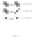
- FIG. 6 illustrates calculation of a stain level performed by referring to pixels surrounding a pixel of interest in an embodiment
- FIG. 7 illustrates a first stain determination method performed by a stain determination unit according to an embodiment
- FIG. 8 is a flowchart illustrating operations of the first stain determination method illustrated in FIG. 7 ;
- FIG. 9 illustrates a second stain determination method performed by the stain determination unit according to an embodiment
- FIG. 10 is a flowchart illustrating operations of the second stain determination method illustrated in FIG. 9 ;
- FIG. 11 is a block diagram illustrating a configuration of a stain detection system according to a second embodiment
- FIG. 12A is a flowchart illustrating operations of the stain detection system according to the second embodiment
- FIG. 12B is a flowchart illustrating operations of the stain detection system according to the second embodiment
- FIG. 13 is a block diagram illustrating a configuration of a stain detection system according to a third embodiment
- FIG. 14A is a flowchart illustrating operations of a stain detection system according to the third embodiment
- FIG. 14B is a flowchart illustrating operations of the stain detection system according to the third embodiment.
- FIG. 14C is a flowchart illustrating operations of the stain detection system according to the third embodiment.
- FIG. 15 is a block diagram illustrating a configuration of a stain detection system according to a fourth embodiment
- FIG. 16A is a flowchart illustrating operations of the stain detection system according to the fourth embodiment.
- FIG. 16B is a flowchart illustrating operations of the stain detection system according to the fourth embodiment.
- FIG. 17 is a flowchart illustrating operations of a stain level storage initialization unit according to the fourth embodiment.
- FIG. 1 is a block diagram illustrating a configuration of a system of detecting a stain according to a first embodiment.
- a system of detecting a stain according to the first embodiment includes an image pickup unit 11 that does not have a movable system and is fixed at one point for continuously picking up images for a monitoring purpose or the like; a picked-up image storage unit 12 for storing images picked up by the image pickup unit 11 ; a subject region extraction unit 13 for detecting that a target subject (such as a vehicle) is in the picked-up image stored in the picked-up image storage unit 12 , extracting the region of the subject, and generating a region extraction image; a region extraction image storage unit 14 for accumulating at least the two most recently picked-up images which undergo region extraction performed by the subject region extraction unit 13 ; a stain level calculation unit 15 for calculating a stain level by comparing, on a pixel-by-pixel basis, a plurality of region extraction images accumulated in the region extraction image storage unit 14
- FIGS. 2A and 2B illustrate a flowchart for the operations of the system of detecting a stain according to the first embodiment.
- the image pickup unit 11 picks up a latest image I 1 .
- the picked-up image I 1 is stored in the picked-up image storage unit 12 .
- the subject region extraction unit 13 processes the image I 1 stored in the picked-up image storage unit 12 in order to extract the region of the target subject, and generates a region extraction image E 1 .
- the image E 1 of the extracted subject region is stored in the region extraction image storage unit 14 . If there is an image that is stored as the image E 1 in the region extraction image storage unit 14 , that image is stored as a previous image E 2 .
- step S 15 the pixel coordinate variables (X, Y) specifying an arbitrary single pixel in the image are initialized by the stain level calculation unit 15 to the values that specify the first pixel (top-left pixel or the like).
- step S 16 pixel value A 1 of the pixel specified by the pixel coordinate variables (X, Y) is read from the latest image E 1 stored in the region extraction image storage unit 14 .
- step S 17 pixel value A 2 of the pixel specified by the pixel coordinate variables (X, Y) is read from the previous image E 2 stored in region extraction image storage unit 14 .
- a stain level P 1 representing whether or not a stain is present on the pixel is calculated on the basis of the pixel values A 1 and A 2 .
- step S 19 in FIG. 2B a stain level P 2 of the pixel specified by the pixel coordinate variables (X, Y) of the stain level storage unit 16 are read out.
- step S 20 a new stain level P 3 is calculated from the stain levels P 1 and P 2 .
- step S 21 P 3 is written as the value of the stain level of the pixel specified by the pixel coordinate variables (X, Y) in the stain level storage unit 16 .
- step S 22 it is determined whether or not the pixel specified by the pixel coordinate variables (X, Y) is the last pixel; in other words, it is determined whether or not all the pixels have been processed. If all the pixels have not been processed, the process proceeds to step S 23 , the pixel coordinate variables (X, Y) are updated to values specifying the next pixel in step S 23 , and the process returns to step S 16 in FIG. 2A . If all the pixels have been processed, the process proceeds to step S 24 , and a value P as the total of the stain levels of all the pixels stored in the stain level storage unit 16 is obtained by the stain determination unit 17 , and the value P is compared with a stain determination threshold value P th in step S 24 .
- step S 25 it is determined whether or not the value P is greater than the threshold value P th . If the value P is greater, the process proceeds to step S 26 , and it is determined that “stain is present” in step S 26 , and this result is output, and thereafter the process is terminated. When the value P is not greater, the process proceeds to step S 27 , and it is determined that “stain is not present”, and thereafter the process returns to step S 11 in FIG. 2A .
- the subject region is extracted from each of the picked-up images before comparing the pixel values of a plurality of picked-up images to each other, and thereby it is possible to certainly detect only stains that are on the target subject and that would therefore interfere with the process.
- the stain level calculation unit repeats the comparisons between a plurality of images in order to extract pixels with a high probability of involving stains, and the stain determination unit determines whether or not a pixel involves a stain on the basis of the probability information. Accordingly, a pattern that seems to be a stain at first glance in one image is not determined to be a stain by mistake.
- the embodiment unlike the conventional methods, it is not necessary to perform an initial setting (calibration) such as picking up a reference image (reference sheet or the like) before the operation so that the operation can be started very easily.
- the user cleans or exchanges devices in accordance with the output from the stain determination unit, and thereby it is possible to avoid a decrease in ability in the monitoring device or the like, which would be caused if operation was continued with a stain present on the device.
- this system does not require hardware dedicated to the stain detection or the setting of different photography conditions by mechanically driving an image-pickup system, and accordingly the stain detection is realized by a device without a driving unit so that the manpower and labor that would be required for maintenance when having a driving system are saved, and thereby lower costs than the conventional methods can be realized.
- FIG. 3 is a chart illustrating the conceptual operation of the system of detecting a stain according to the above described first embodiment.
- FIG. 3 illustrates an example in which a camera fixed at a single point is used as the image pickup unit 11 . This camera continuously picks up images and accumulates the picked-up images in the picked-up image storage unit 12 .
- the subject region extraction unit 13 extracts only the subject regions (the target subject is the vehicle in this example) and stores the subject regions in the region extraction image storage unit 14 .
- only the region including the photography target is the target of the stain detection so that only stains/foreign objects on the subject are detected and the background around the subject is not detected to be a stain or a foreign object by mistake.
- the stain level calculation unit 15 compares the pixels in the regions extracted from two or more images. The fact that a present stain is included in images at the same position and with the same pixel value even when different subjects are photographed is utilized. The pixels having the same pixel value are stored in the stain level storage unit 16 as stain candidates. When this process is performed, a stain is not determined to be present only on the basis of one comparison, and the stain level is raised or lowered on the basis of the comparison results. By repeating this comparison between images many times, the stain levels at the respective pixels gradually converge so that the stain level of an actual stain increases and the stain level of a portion that is not actually a stain decreases.
- the content of the function can be selected arbitrarily; however, in a function in which when the absolute value of the difference between the pixels, i.e., (A(x, y) ⁇ B(x, y)), is the smallest, the stain level P has the maximum value; in other words a function that has the characteristics illustrated in, for example, FIG. 4 is used.
- a table as illustrated in FIG. 5 is referred to, and the referred value is used as the value of stain level P (when the value is not included in the table, the value close to it is used for the interpolation, and the value obtained by the interpolation is used as the value of the stain level).
- the vertical axis represents pixel values A(x, y) of an arbitrary coordinate (x, y) in the latest image
- the horizontal axis represents pixel values B(x, y) of an arbitrary coordinate (x, y) in the previous image.
- the table in FIG. 5 is a table for a stain detection filtering process in which the stain level P of a pixel becomes high when the pixel is close to black and A(x, y) and B(x, y) are close to each other.
- FIG. 6 illustrates a third method of calculating a stain level.
- the stain level P is calculated using not only the pixel value of that coordinate (x, y) but also the pixel values of pixels close to the coordinate (x, y). In this case, only when the center pixels have the same pixel value and the pixels close to the center pixel have similar pixel values is it determined that the stain level is high, as illustrated in FIG. 6( a ). Also, when an image does not have an image pattern specific to images with a stain, it is determined that the stain level is low, as illustrated in FIG. 6( c ). Also, when the center pixels have the same pixel value but the pixels close to the center pixels do not have similar values, it is determined that the stain level is low as illustrated in FIG. 6( b ).
- stain determination method performed by the stain determination unit according to the embodiments will be explained.
- stain determination methods described below can be employed.
- a first stain determination method is a method in which, as illustrated in FIG. 7 , the total stain level of the entire image stored in the stain level storage unit is obtained, and when this total value exceeds a prescribed threshold value P_sum_thresh, it is determined that a stain is present.
- P_sum_thresh a prescribed threshold value
- FIG. 8 is a flowchart for the first stain determination method according to the embodiments.
- step S 31 in FIG. 8 the stain level total value P_sum is initialized.
- step S 32 the pixel coordinate variables (x, y) specifying an arbitrary pixel in the image are initialized to values that specify the initial pixel (top-left pixel or the like).
- step S 33 stain level P (x, y) of the pixel coordinate variables (x, y) is read from the stain level storage unit.
- step S 34 the stain level total value P_sum of the entire image and the read stain level P (x, y) are added together, and the stain level total value P_sum of the entire image is updated.
- step S 35 it is determined whether or not the pixel coordinate variables (x, y) are for the last pixel in the image; in other words, whether or not all the pixels have been processed.
- step S 36 If all the pixels have not been processed, the process proceeds to step S 36 , and the pixel coordinate variables (x, y) are updated to values specifying the next pixel in step S 36 , and the process returns to step S 33 . If all the pixels have been processed, the process proceeds to step S 37 , and it is determined whether or not the stain level total value P_sum of the entire image exceeds the threshold value P_sum_thresh. When the value exceeds the threshold value, the process proceeds to step S 38 , and it is determined that “stain is present” in step S 38 , and the stain determination is terminated. When the value does not exceed the threshold value, the process proceeds to step S 39 , and it is determined that “stain is not present” in step S 39 , and the stain determination is terminated.
- a second stain determination method is a method in which, as illustrated in FIG. 9 , the stain levels throughout the entirety of the image stored in the stain level storage unit are sequentially checked, and the number “N” of pixels with stain levels higher than the predetermined threshold value N_thresh is obtained, and when the number “N” of such pixels exceeds the predetermined threshold value N_thresh, it is determined that a stain is present.
- this method it is possible to determine, to be stains, dark stains or parts that can be definitely determined to be stains. It is also possible to perform this determination on the basis of the total area of pixels with stain levels higher than the threshold value instead of the total number “N” of such pixels.
- FIG. 10 illustrates a flowchart for the second stain determination method according to the embodiments.
- step S 41 in FIG. 10 the number “N” of pixels with stain levels higher than the threshold value P_thresh is initialized.
- step S 42 the pixel coordinate variables (x, y) specifying an arbitrary pixel in an image are initialized to values that specify the initial pixel (top-left pixel or the like).
- step S 43 stain level P (x, y) of the pixel coordinate variables (x, y) is read from the stain level storage unit.
- step S 44 it is determined whether or not the stain level (x, y) exceeds the threshold value P_thresh.
- step S 45 When the above stain level is determined to not exceed the threshold value P_thresh, the process proceeds to step S 45 , and the pixel coordinate variables (x, y) are updated to values specifying the next pixel in step S 45 , and the process returns to step S 43 .
- the process proceeds to step S 46 , and the number “N” of pixels is incremented in step S 46 .
- step S 47 it is determined whether or not the pixel coordinate variables (x, y) are for the last pixel in the image; in other words, whether or not all the pixels have been processed.
- step S 45 If all the pixels have not been processed, the process proceeds to step S 45 , and the pixel coordinate variables (x, y) are updated to values specifying the next pixel in step S 45 , and the process returns to step S 43 . If all the pixels have been processed, the process proceeds to step S 48 , and it is determined whether or not the total number “N” of pixels exceeds the predetermined threshold value N_thresh. When the number exceeds the threshold value, the process proceeds to step S 49 , and it is determined that “stain is present” in step S 49 , and the stain determination is terminated. When the number does not exceed the threshold value, the process proceeds to step S 50 , and it is determined that “stain is not present” in step S 50 , and the stain determination is terminated.
- the stain determination unit determines the presence or absence of stains, and outputs the presence or absence of stains and the degree that the stains are present. Because the stain determination unit outputs the presence or absence of stains and the degree that the stains are present, it is possible to issue warnings before definitely determining that a stain is present. It is also possible to check the changes of states of the sensor by logging the determination results.
- FIG. 11 is a block diagram illustrating a configuration of a system of detecting a stain according to the second embodiment.
- the system of detecting a stain according to the second embodiment comprises an image pickup unit 21 that does not have a movable system and is fixed at one point for continuously picking up images for monitoring, etc.; a picked-up image storage unit 22 for storing images picked, up by the image pickup unit 21 ; a subject region extraction unit 23 for detecting that a target subject (such as a vehicle) is in the picked-up image stored in the picked-up image storage unit 22 , extracting the region of the subject, and generating a region extraction image; a region extraction image storage unit 24 for accumulating at least two recently picked-up images which undergo region extraction performed by the subject region extraction unit 23 ; a region extraction image amendment unit 25 for calculating a total luminance of all pixels in the region extraction image, amending the luminance to correspond to the predetermined luminance standard, and reaccumulating the region extraction image in the region extraction image storage unit
- FIGS. 12A and 12B illustrate a flowchart for the system of detecting a stain according to the second embodiment.
- the image pickup unit 21 picks up the latest image I 1 .
- the picked-up image I 1 is stored in the picked-up image storage unit 22 .
- the subject region extraction unit 23 performs image processing on the image I 1 stored in the picked-up image storage unit 22 so that the region including the target subject is extracted, and a region extraction image E 1 is generated.
- the image E 1 of the extracted subject region is stored in the region extraction image storage unit 24 .
- step S 55 the region extraction image amendment unit 25 calculates the total luminance V 1 of all the pixels in the region extraction image E 1 , and performs the luminance amendment by multiplying all the pixels in the region extraction image by V 0 /V 1 so that the total luminance corresponds to the predetermined reference luminance V 0 , and the images are again stored in the region extraction image storage unit 24 .
- step S 56 the pixel coordinate variables (X, Y) specifying an arbitrary single pixel in the image are initialized by the stain level calculation unit 26 to the values that specify the first pixel (top-left pixel or the like).
- step S 57 pixel value A 1 of the pixel specified by the pixel coordinate variables (X, Y) is read from the latest image E 1 stored in the region extraction image storage unit 24 .
- step S 58 a pixel value A 2 of the pixel specified by the pixel coordinate variables (X, Y) is read from the previous image E 2 stored in the region extraction image storage unit 24 .
- a stain level P 1 representing whether or not a stain is present on the pixel is calculated on the basis of the pixel values A 1 and A 2 .
- a stain level P 2 of the pixel specified by the pixel coordinate variables (X, Y) of the stain level storage unit 27 is read out.
- a new stain level P 3 is calculated from the stain levels P 1 and P 2 .
- P 3 is written as the value of the stain level of the pixel specified by the pixel coordinate variables (X, Y) in the stain level storage unit 27 .
- step S 63 it is determined whether or not the pixel specified by the pixel coordinate variables (X, Y) is the last pixel; in other words, it is determined whether or not all the pixels have been processed. If all the pixels have not been processed, the process proceeds to step S 64 , the pixel coordinate variables (X, Y) are updated to values specifying the next pixel in step S 64 , and the process returns to step S 57 in FIG. 12A . If all the pixels have been processed, the process proceeds to step S 65 , and a value P as the total of the stain levels of all the pixels stored in the stain level storage unit 27 is obtained by the stain determination unit 28 , and the value P is compared with a stain determination threshold value P th in step S 65 .
- step S 66 it is determined whether or not the value P is greater than the threshold value P th . If the value P is greater, the process proceeds to step S 67 , and it is determined that “stain is present” in step S 67 , and this result is output, and thereafter the process is terminated. When the value P is not greater, the process proceeds to step S 68 , and it is determined that “stain is not present” in step S 68 , and thereafter the process returns to step S 51 in FIG. 12A .
- the pixels to be compared undergo amendment on the basis of the luminance level of the region extraction image, so that a pixel comparison similar to the comparison of pixels picked up under the same photography conditions can be performed even when the images were picked up under different photography conditions, and thereby it is possible to calculate appropriate stain levels. Also, it is possible to increase the accuracy of stain determination by decreasing the stain levels of pixels having pixel values that can be definitely determined not to be influenced by a stain (such as pixels with high luminance) in the region extraction image before the stain level calculation.
- FIG. 13 illustrates a block diagram illustrating a configuration of a system of detecting a stain according to the third embodiment.
- the system of detecting a stain according to the third embodiment includes an image pickup unit 31 that does not have a movable system and is fixed at one point for continuously picking up images for monitoring, etc.; a picked-up image storage unit 32 for storing images picked up by the image pickup unit 31 ; a subject region extraction unit 33 for detecting that a target subject is in the picked-up image stored in the picked-up image storage unit 32 , extracting the region of the subject, and generating a region extraction image; a region extraction image storage unit 34 for accumulating a plurality of images which are recently picked up and which undergo region extraction performed by the subject region extraction unit 33 and accumulating extraction region mask information for determining whether or not a pixel is in the subject region with respect to a boundary for the region extraction; a stain level calculation unit 35 for calculating a stain level by comparing, on a pixel-by
- FIGS. 14A , 14 B, and 14 C illustrate a flowchart for the operations of the system of detecting a stain according to the third embodiment.
- the image pickup unit 31 picks up the latest image I 1 .
- the picked-up image I 1 is stored in the picked-up image storage unit 32 .
- the subject region extraction unit 33 performs image processing on the image I 1 stored in a picked-up image storage unit 72 so that the region including the target subject is extracted, and a region extraction image E 1 and extraction region mask information M 1 are generated.
- step S 74 if the image E 1 and the extraction region mask information M 1 of an extracted subject region are stored in a region extraction image storage unit 74 , the image that is already stored as the image E 1 and information already stored as the mask information M 1 in the region extraction image storage unit 74 are stored as a previous image E 2 and previous mask information M 2 , respectively.
- step S 75 the pixel coordinate variables (X, Y) specifying an arbitrary pixel in the image are initialized by the stain level calculation unit 35 to the values that specify the first pixel (top-left pixel or the like).
- step S 76 pixel value A 1 of the pixel specified by the pixel coordinate variables (X, Y) is read from the latest image E 1 stored in the region extraction image storage unit 34 .
- step S 77 a pixel value A 2 of the pixel specified by the pixel coordinate variables (X, Y) is read from the previous image E 2 stored in the region extraction image storage unit 34 .
- step S 78 the stain level P 1 representing whether or not a stain is present on the pixel is calculated from the pixel values A 1 and A 2 .
- step S 79 in FIG. 14B the stain level P 2 of the pixel specified by the pixel coordinate variables (X, Y) of the stain level storage unit 36 is read out.
- step S 80 the new stain level P 3 is calculated from the stain levels P 1 and P 2 .
- step S 81 P 3 is written as the stain value of the pixel specified by the pixel coordinate variables (X, Y) of the stain level storage unit 36 .
- step S 82 it is determined whether or not the pixel specified by the pixel coordinate variables (X, Y) is the last pixel in the image; in other words, it is determined whether or not all the pixels have been processed. If all the pixels have not been processed, the process proceeds to step S 83 , the pixel coordinate variables (X, Y) are updated to values specifying the next pixel in step S 83 , and the process returns to step S 76 in FIG. 14A .
- step S 84 the stain determination unit 37 initializes the pixel coordinate variables (x, y) specifying an arbitrary pixel in the image to values that specify the first pixel (top-left pixel or the like)
- step S 85 the stain level P (x, y) of the pixel coordinate variables is read from the stain level storage unit 36 .
- step S 86 the extraction region mask information M (x, y) of the pixel coordinate variables (x, y) is read from the region extraction image storage unit 34 .
- step S 87 in FIG. 14C when the extraction region mask information M (x, y) is greater than zero, the stain level P (x, y) is multiplied by the coefficient K 1 in order to create a new stain level P (x, y), and when the extraction region mask information M (x, y) is zero, the stain level P (x, y) is multiplied by the coefficient K 2 in order to create a new stain level P (x, y).
- the coefficient K 1 is greater than the coefficient K 2 , and both coefficients K 1 and K 2 are between one and zero.
- step S 87 when the extraction region mask information M (x, y) of the pixel coordinate variables (x, y) is greater than zero (this means that the pixel is in the subject region with respect to the boundary of the subject region), the stain level is evaluated with a weight for the pixel coordinate variables (x, y) concerned, where the weight is higher than another weight with which the stain level is evaluated when the extraction region mask information M (x y) of the pixel coordinate variables (x, y) is zero (this means that the pixel is not in the subject region with respect to the boundary of the subject region).
- step S 88 it is determined whether or not the pixel specified by the pixel coordinate variables (x, y) is the last pixel in the image; in other words, it is determined whether or not all the pixels have been processed. If all the pixels have not been processed, the process proceeds to step S 89 , the pixel coordinate variables (x, y) are updated to values specifying the next pixel in step S 89 , and the process returns to step S 85 in FIG. 14B . If all the pixels have been processed, the process proceeds to step S 90 , and the value P is calculated by summing the P (x, y) of the stains of all the pixels, and P is compared with the stain determination threshold value P th .
- step S 91 it is determined whether or not the value P is greater than the threshold value P th . If the value P is greater, the process proceeds to step S 92 , it is determined that “stain is present” in step S 92 , the determination result is output, and thereafter the process is terminated. When the value P is not greater, the process proceeds to step S 93 , it is determined that “stain is not present”, and thereafter the process returns to step S 71 in FIG. 14A .
- the stain level of the pixel extracted as the subject region by the subject region extraction unit is given a weight greater than that given to the stain level of the pixels out of the subject region. Accordingly, it is possible to not detect stains present on unimportant portions such as corners (not on the subject), but to mainly detect stains on the subject.
- FIG. 15 is a block diagram illustrating a configuration of a system of detecting a stain according to a fourth embodiment.
- the system of detecting a stain according to the fourth embodiment includes an image pickup unit 41 that does not have a movable system and is fixed at one point for continuously picking up images for monitoring, etc.; a picked-up image storage unit 42 for storing images picked up by the image pickup unit 41 ; a subject region extraction unit 43 for detecting that a target subject (such as a vehicle) is in the picked-up image stored in the picked-up image storage unit 42 , extracting the region of the subject, and generating a region extraction image; a region extraction image storage unit 44 for accumulating at least two images which are recently picked up and which undergo region extraction performed by the subject region extraction unit 43 ; a stain level calculation unit 45 for calculating a stain level by comparing, on a pixel-by-pixel basis, the plurality of region extraction images accumulated in the region extraction image storage unit 44 with other pixels; a
- FIGS. 16A and 16B illustrate a flowchart for the system of detecting a stain according to the fourth embodiment.
- the image pickup unit 41 picks up a latest image I 1 .
- the picked-up image I 1 is stored in the picked-up image storage unit 42 .
- the subject region extraction unit 43 performs image processing on the image I 1 stored in the picked-up image storage unit 42 so that the region including the target subject is extracted, and a region extraction image E 1 is generated.
- the image E 1 of the extracted subject region is stored in the region extraction image storage unit 44 . If there is an image that is already stored as the image E 1 , that image is stored as the previous image E 2 .
- step S 105 it is checked whether or not the stain level storage unit 46 is locked, and the process proceeds to step S 106 after confirming that the stain level storage unit 46 is not locked.
- step S 106 the stain level storage unit 46 is locked.
- the initialization operations of the stain level storage unit 46 relating to these operations will be explained in detail in FIG. 17 .
- step S 107 the stain level calculation unit 45 initializes the pixel coordinate variables (X, Y) specifying an arbitrary pixel in the image to a value that specifies the first pixel (top-left pixel or the like).
- step S 108 the pixel value A 1 of the pixel specified by the pixel coordinate variables (X, Y) is read from the latest image E 1 stored in the region extraction image storage unit 44 .
- step S 109 a pixel value A 2 of the pixel specified by the pixel coordinate variables (X, Y) is read from the previous image E 2 stored in the region extraction image storage unit 44 .
- step S 110 in FIG. 16B the stain level P 1 representing whether or not a stain is present on the pixel is calculated from the pixel values A 1 and A 2 .
- step S 111 the stain level P 2 of the pixel specified by the pixel coordinate variables (X, Y) in the stain level storage unit 46 is read out.
- step S 112 a new stain level P 3 is calculated from the stain levels P 1 and P 2 .
- P 3 is written as the stain value of the pixel specified by the pixel coordinate variables (X, Y) of the stain level storage unit 46 .
- step S 114 it is determined whether or not the pixel specified by the pixel coordinate variables (X, Y) is the last pixel in the image; in other words, it is determined whether or not all the pixels have been processed. If all the pixels have not been processed, the process proceeds to step S 115 , the pixel coordinate variables (X, Y) are updated to values specifying the next pixel in step S 115 , and the process returns to step S 108 in FIG. 16A . If all the pixels have been processed, the process proceeds to step S 116 , and the stain determination unit 47 obtains the value P by summing the stains of all the pixels stored in the stain level storage unit 46 , and compares P with the stain determination threshold value P th .
- step S 117 the locking of the stain level storage unit 46 is cancelled.
- step S 118 it is determined whether value P is greater than the threshold value P th . If the value P is greater, the process proceeds to step S 119 , and it is determined that “stain is present” in step S 119 , and the determination result is output, and thereafter the process is terminated. When the value P is not greater, the process proceeds to step S 120 , and it is determined that “stain is not present” in step S 120 , and thereafter the process returns to step S 101 in FIG. 16A .
- FIG. 17 illustrates a flowchart for the operation of the stain level storage initialization unit according to the fourth embodiment.
- the stain level storage initialization unit 48 is activated by the periodical timer outputs from the timer 49 .
- step S 121 it is confirmed that the stain level storage unit 46 is not locked after checking whether or not the stain level storage unit 46 is locked, and the process proceeds to step S 122 .
- step S 122 the stain level storage unit 46 is locked.
- step S 123 the values of the stain levels of all the pixels in the stain level storage unit 46 are initialized to zero.
- step S 124 the lock on the stain level storage unit 46 is cancelled. Then, the operation of the stain level storage initialization is terminated.
- the method of detecting a stain in the fourth embodiment it is possible, by periodically initializing the storage contents of the storage level storage unit, to avoid a situation in which invalid information is left in the stain storage unit as a result of processes performed for a long period. Thereby, it is possible to maintain accuracy in stain determination.
Landscapes
- Engineering & Computer Science (AREA)
- Computer Vision & Pattern Recognition (AREA)
- Physics & Mathematics (AREA)
- General Physics & Mathematics (AREA)
- Theoretical Computer Science (AREA)
- Quality & Reliability (AREA)
- Multimedia (AREA)
- Signal Processing (AREA)
- Image Analysis (AREA)
- Studio Devices (AREA)
- Image Processing (AREA)
- Closed-Circuit Television Systems (AREA)
Abstract
Description
- Japanese Patent Application Publication No. 2001-8193
- Japanese Patent Application Publication No. 2004-172820
P=F(A(x,y),B(x,y))
Claims (10)
Applications Claiming Priority (1)
| Application Number | Priority Date | Filing Date | Title |
|---|---|---|---|
| PCT/JP2006/311527 WO2007141858A1 (en) | 2006-06-08 | 2006-06-08 | Uncleanness detecting device |
Related Parent Applications (1)
| Application Number | Title | Priority Date | Filing Date |
|---|---|---|---|
| PCT/JP2006/311527 Continuation WO2007141858A1 (en) | 2006-06-08 | 2006-06-08 | Uncleanness detecting device |
Publications (2)
| Publication Number | Publication Date |
|---|---|
| US20090087022A1 US20090087022A1 (en) | 2009-04-02 |
| US8098302B2 true US8098302B2 (en) | 2012-01-17 |
Family
ID=38801130
Family Applications (1)
| Application Number | Title | Priority Date | Filing Date |
|---|---|---|---|
| US12/329,860 Expired - Fee Related US8098302B2 (en) | 2006-06-08 | 2008-12-08 | Stain detection system |
Country Status (6)
| Country | Link |
|---|---|
| US (1) | US8098302B2 (en) |
| EP (1) | EP2031557B1 (en) |
| JP (1) | JP4644283B2 (en) |
| KR (1) | KR101078474B1 (en) |
| CN (1) | CN101460971B (en) |
| WO (1) | WO2007141858A1 (en) |
Cited By (9)
| Publication number | Priority date | Publication date | Assignee | Title |
|---|---|---|---|---|
| US20180307926A1 (en) * | 2017-04-21 | 2018-10-25 | Ford Global Technologies, Llc | Stain and Trash Detection Systems and Methods |
| US10290158B2 (en) | 2017-02-03 | 2019-05-14 | Ford Global Technologies, Llc | System and method for assessing the interior of an autonomous vehicle |
| US10304165B2 (en) | 2017-05-12 | 2019-05-28 | Ford Global Technologies, Llc | Vehicle stain and trash detection systems and methods |
| US10311314B2 (en) | 2016-11-23 | 2019-06-04 | Ford Global Technologies, Llc | Detection of lane-splitting motorcycles |
| US10638093B2 (en) | 2013-09-26 | 2020-04-28 | Rosemount Inc. | Wireless industrial process field device with imaging |
| US10823592B2 (en) | 2013-09-26 | 2020-11-03 | Rosemount Inc. | Process device with process variable measurement using image capture device |
| US10914635B2 (en) | 2014-09-29 | 2021-02-09 | Rosemount Inc. | Wireless industrial process monitor |
| US11076113B2 (en) | 2013-09-26 | 2021-07-27 | Rosemount Inc. | Industrial process diagnostics using infrared thermal sensing |
| US20220011242A1 (en) * | 2020-07-09 | 2022-01-13 | Hyundai Motor Company | Vehicle and method of managing cleanliness of interior of the same |
Families Citing this family (29)
| Publication number | Priority date | Publication date | Assignee | Title |
|---|---|---|---|---|
| JP5188293B2 (en) * | 2008-07-03 | 2013-04-24 | キヤノン株式会社 | Imaging apparatus, control method thereof, and program |
| US8665347B2 (en) | 2009-07-21 | 2014-03-04 | Nikon Corporation | Image processing device, image processing program, and imaging device computing brightness value and color phase value |
| JP2011078047A (en) * | 2009-10-02 | 2011-04-14 | Sanyo Electric Co Ltd | Imaging apparatus |
| WO2011108582A1 (en) * | 2010-03-04 | 2011-09-09 | 日本電気株式会社 | Foreign object assessment device, foreign object assessment method, and foreign object assessment program |
| JP5953658B2 (en) * | 2011-05-25 | 2016-07-20 | ソニー株式会社 | ROBOT CONTROL DEVICE, ROBOT DEVICE CONTROL METHOD, COMPUTER PROGRAM, PROGRAM STORAGE MEDIUM, AND ROBOT DEVICE |
| JP2014011785A (en) * | 2012-07-03 | 2014-01-20 | Clarion Co Ltd | Diagnostic device and diagnostic method for on-vehicle camera contamination removal apparatus, and vehicle system |
| WO2014017317A1 (en) * | 2012-07-27 | 2014-01-30 | 日産自動車株式会社 | Three-dimensional object detection device and foreign object detection device |
| JP6102213B2 (en) * | 2012-11-22 | 2017-03-29 | 富士通株式会社 | Image processing apparatus, image processing method, and image processing program |
| CN105389577A (en) * | 2014-08-25 | 2016-03-09 | 中兴通讯股份有限公司 | Dirt detection method, device and terminal |
| KR101672116B1 (en) * | 2015-02-02 | 2016-11-02 | 울산대학교 산학협력단 | Car washing system and washing method thereof |
| CN104867159B (en) * | 2015-06-05 | 2018-04-10 | 北京大恒图像视觉有限公司 | A kind of digital camera sensor dust detection and stage division and device |
| CN106803252A (en) * | 2017-01-16 | 2017-06-06 | 广东容祺智能科技有限公司 | A kind of dirty positioning of power transmission line column number plate and automatic testing method |
| JP7092984B2 (en) | 2017-12-01 | 2022-06-29 | 富士通株式会社 | Bioimage processing device, bioimage processing method, and bioimage processing program |
| US10795618B2 (en) | 2018-01-05 | 2020-10-06 | Datamax-O'neil Corporation | Methods, apparatuses, and systems for verifying printed image and improving print quality |
| US10546160B2 (en) | 2018-01-05 | 2020-01-28 | Datamax-O'neil Corporation | Methods, apparatuses, and systems for providing print quality feedback and controlling print quality of machine-readable indicia |
| US10834283B2 (en) | 2018-01-05 | 2020-11-10 | Datamax-O'neil Corporation | Methods, apparatuses, and systems for detecting printing defects and contaminated components of a printer |
| US10803264B2 (en) | 2018-01-05 | 2020-10-13 | Datamax-O'neil Corporation | Method, apparatus, and system for characterizing an optical system |
| IL260417B (en) * | 2018-07-04 | 2021-10-31 | Tinyinspektor Ltd | System and method for automatic visual inspection |
| ES2965814T3 (en) * | 2019-02-27 | 2024-04-17 | Daikin Ind Ltd | Information delivery system |
| CN109862202B (en) * | 2019-03-29 | 2021-11-30 | 富士施乐实业发展(中国)有限公司 | Method and device for controlling manuscript conveyor of compound machine |
| CN109936676B (en) * | 2019-03-29 | 2020-12-18 | 富士施乐实业发展(中国)有限公司 | Method and device for controlling manuscript conveyor of compound machine |
| CN110166769B (en) * | 2019-06-27 | 2020-10-02 | 信利光电股份有限公司 | Method, device and system for detecting output dislocation of camera module and storage medium |
| JP7156224B2 (en) * | 2019-09-20 | 2022-10-19 | 株式会社デンソーテン | Attached matter detection device and attached matter detection method |
| KR102157005B1 (en) * | 2019-12-12 | 2020-09-16 | 주식회사 제이시스 | Method of improving precision of deep learning resultant image by using image filtering technique |
| EP3839908B1 (en) * | 2019-12-17 | 2025-06-18 | Axis AB | Close object detection for surveillance cameras |
| CN111275022B (en) * | 2020-03-19 | 2023-05-16 | 山东宜佳成新材料有限责任公司 | Stain detection analysis method based on forgetting factor type empirical mode decomposition and application |
| CN111739012A (en) * | 2020-06-30 | 2020-10-02 | 重庆盛泰光电有限公司 | Camera module white spot detecting system based on turntable |
| CN111812341A (en) * | 2020-07-22 | 2020-10-23 | 英华达(上海)科技有限公司 | Automatic equipment detection system and method for detecting internal operation of automatic equipment |
| CN113458072B (en) * | 2021-07-06 | 2022-01-18 | 广东固特超声股份有限公司 | Intelligent terminal controlled ultrasonic cleaning method and cleaning machine for glasses |
Citations (14)
| Publication number | Priority date | Publication date | Assignee | Title |
|---|---|---|---|---|
| JPS60124783A (en) | 1983-12-10 | 1985-07-03 | Meidensha Electric Mfg Co Ltd | Picture processing unit |
| JPH08202998A (en) | 1995-01-31 | 1996-08-09 | Isuzu Motors Ltd | Lane departure warning device |
| JPH11195121A (en) | 1997-12-29 | 1999-07-21 | Canon Inc | Image evaluation apparatus and method |
| JP2001008193A (en) | 1999-06-24 | 2001-01-12 | Secom Co Ltd | Image sensor |
| JP2002094978A (en) | 2000-09-18 | 2002-03-29 | Toyota Motor Corp | Lane detector |
| JP2002290994A (en) | 2001-03-26 | 2002-10-04 | Sharp Corp | Foreign object inspection method for small camera module and foreign object inspection device |
| JP2003259358A (en) | 2002-03-06 | 2003-09-12 | Nissan Motor Co Ltd | Camera dirt detection device and camera dirt detection method |
| US20040041936A1 (en) * | 2002-08-30 | 2004-03-04 | Nikon Corporation | Electronic amera and control program of same |
| JP2004172820A (en) | 2002-11-19 | 2004-06-17 | Minolta Co Ltd | Imaging device |
| US20050078173A1 (en) * | 2003-09-30 | 2005-04-14 | Eran Steinberg | Determination of need to service a camera based on detection of blemishes in digital images |
| JP2005117262A (en) | 2003-10-06 | 2005-04-28 | Fujitsu Ltd | Lens dirt determination method and apparatus |
| US20070159551A1 (en) * | 2006-01-12 | 2007-07-12 | Takuya Kotani | Image capturing apparatus, control method thereof, and program |
| US7778542B2 (en) * | 2006-06-20 | 2010-08-17 | Canon Kabushiki Kaisha | Image capturing apparatus |
| US20100226532A1 (en) * | 2006-07-10 | 2010-09-09 | Toyota Jidosha Kabushiki Kaisha | Object Detection Apparatus, Method and Program |
Family Cites Families (3)
| Publication number | Priority date | Publication date | Assignee | Title |
|---|---|---|---|---|
| JP2003209749A (en) * | 2002-01-11 | 2003-07-25 | Olympus Optical Co Ltd | Imaging device |
| JP2003295281A (en) * | 2002-04-03 | 2003-10-15 | Canon Inc | Imaging apparatus, operation processing method, program, and storage medium |
| JP2004153422A (en) * | 2002-10-29 | 2004-05-27 | Toshiba Corp | Photographing apparatus, face collating apparatus, dirt detection method of photographing apparatus, and face collating method |
-
2006
- 2006-06-08 JP JP2008520094A patent/JP4644283B2/en not_active Expired - Fee Related
- 2006-06-08 WO PCT/JP2006/311527 patent/WO2007141858A1/en not_active Ceased
- 2006-06-08 CN CN2006800548522A patent/CN101460971B/en not_active Expired - Fee Related
- 2006-06-08 EP EP06766500.0A patent/EP2031557B1/en not_active Ceased
- 2006-06-08 KR KR1020087029606A patent/KR101078474B1/en not_active Expired - Fee Related
-
2008
- 2008-12-08 US US12/329,860 patent/US8098302B2/en not_active Expired - Fee Related
Patent Citations (15)
| Publication number | Priority date | Publication date | Assignee | Title |
|---|---|---|---|---|
| JPS60124783A (en) | 1983-12-10 | 1985-07-03 | Meidensha Electric Mfg Co Ltd | Picture processing unit |
| JPH08202998A (en) | 1995-01-31 | 1996-08-09 | Isuzu Motors Ltd | Lane departure warning device |
| JPH11195121A (en) | 1997-12-29 | 1999-07-21 | Canon Inc | Image evaluation apparatus and method |
| JP2001008193A (en) | 1999-06-24 | 2001-01-12 | Secom Co Ltd | Image sensor |
| JP2002094978A (en) | 2000-09-18 | 2002-03-29 | Toyota Motor Corp | Lane detector |
| JP2002290994A (en) | 2001-03-26 | 2002-10-04 | Sharp Corp | Foreign object inspection method for small camera module and foreign object inspection device |
| JP2003259358A (en) | 2002-03-06 | 2003-09-12 | Nissan Motor Co Ltd | Camera dirt detection device and camera dirt detection method |
| US20040041936A1 (en) * | 2002-08-30 | 2004-03-04 | Nikon Corporation | Electronic amera and control program of same |
| JP2005072629A (en) | 2002-08-30 | 2005-03-17 | Nikon Corp | Electronic camera and control program thereof |
| JP2004172820A (en) | 2002-11-19 | 2004-06-17 | Minolta Co Ltd | Imaging device |
| US20050078173A1 (en) * | 2003-09-30 | 2005-04-14 | Eran Steinberg | Determination of need to service a camera based on detection of blemishes in digital images |
| JP2005117262A (en) | 2003-10-06 | 2005-04-28 | Fujitsu Ltd | Lens dirt determination method and apparatus |
| US20070159551A1 (en) * | 2006-01-12 | 2007-07-12 | Takuya Kotani | Image capturing apparatus, control method thereof, and program |
| US7778542B2 (en) * | 2006-06-20 | 2010-08-17 | Canon Kabushiki Kaisha | Image capturing apparatus |
| US20100226532A1 (en) * | 2006-07-10 | 2010-09-09 | Toyota Jidosha Kabushiki Kaisha | Object Detection Apparatus, Method and Program |
Non-Patent Citations (2)
| Title |
|---|
| International Search Report of PCT/JP2006/311527, Mailing Date of Jul. 4, 2006. |
| Korean Office Action dated Jan. 24, 2011, issued in corresponding Korean Patent Application No. 10-2008-7029606. |
Cited By (12)
| Publication number | Priority date | Publication date | Assignee | Title |
|---|---|---|---|---|
| US10638093B2 (en) | 2013-09-26 | 2020-04-28 | Rosemount Inc. | Wireless industrial process field device with imaging |
| US10823592B2 (en) | 2013-09-26 | 2020-11-03 | Rosemount Inc. | Process device with process variable measurement using image capture device |
| US11076113B2 (en) | 2013-09-26 | 2021-07-27 | Rosemount Inc. | Industrial process diagnostics using infrared thermal sensing |
| US10914635B2 (en) | 2014-09-29 | 2021-02-09 | Rosemount Inc. | Wireless industrial process monitor |
| US11927487B2 (en) | 2014-09-29 | 2024-03-12 | Rosemount Inc. | Wireless industrial process monitor |
| US10311314B2 (en) | 2016-11-23 | 2019-06-04 | Ford Global Technologies, Llc | Detection of lane-splitting motorcycles |
| US10290158B2 (en) | 2017-02-03 | 2019-05-14 | Ford Global Technologies, Llc | System and method for assessing the interior of an autonomous vehicle |
| US20180307926A1 (en) * | 2017-04-21 | 2018-10-25 | Ford Global Technologies, Llc | Stain and Trash Detection Systems and Methods |
| US10509974B2 (en) * | 2017-04-21 | 2019-12-17 | Ford Global Technologies, Llc | Stain and trash detection systems and methods |
| US10304165B2 (en) | 2017-05-12 | 2019-05-28 | Ford Global Technologies, Llc | Vehicle stain and trash detection systems and methods |
| US20220011242A1 (en) * | 2020-07-09 | 2022-01-13 | Hyundai Motor Company | Vehicle and method of managing cleanliness of interior of the same |
| US11821845B2 (en) * | 2020-07-09 | 2023-11-21 | Hyundai Motor Company | Vehicle and method of managing cleanliness of interior of the same |
Also Published As
| Publication number | Publication date |
|---|---|
| KR101078474B1 (en) | 2011-10-31 |
| CN101460971A (en) | 2009-06-17 |
| WO2007141858A1 (en) | 2007-12-13 |
| US20090087022A1 (en) | 2009-04-02 |
| KR20090009944A (en) | 2009-01-23 |
| EP2031557A4 (en) | 2014-04-16 |
| JPWO2007141858A1 (en) | 2009-10-15 |
| CN101460971B (en) | 2012-06-27 |
| EP2031557B1 (en) | 2017-12-27 |
| JP4644283B2 (en) | 2011-03-02 |
| EP2031557A1 (en) | 2009-03-04 |
Similar Documents
| Publication | Publication Date | Title |
|---|---|---|
| US8098302B2 (en) | Stain detection system | |
| CN106909911B (en) | Image processing method, image processing apparatus, and electronic apparatus | |
| US8054881B2 (en) | Video stabilization in real-time using computationally efficient corner detection and correspondence | |
| US9098748B2 (en) | Object detection apparatus, object detection method, monitoring camera system and storage medium | |
| US6625318B1 (en) | Robust sequential approach in detecting defective pixels within an image sensor | |
| JP4639555B2 (en) | Motion vector detection apparatus and method, camera shake correction apparatus and method, and imaging apparatus | |
| US8923552B2 (en) | Object detection apparatus and object detection method | |
| JPWO2014010174A1 (en) | Angle of view variation detection device, angle of view variation detection method, and field angle variation detection program | |
| EP1395059A2 (en) | Intruding-object detection apparatus | |
| JP4533836B2 (en) | Fluctuating region detection apparatus and method | |
| US20110085026A1 (en) | Detection method and detection system of moving object | |
| US20100262290A1 (en) | Data matching apparatus, data matching method and mobile robot | |
| US11910080B2 (en) | Image pickup apparatus for inferring noise and learning device | |
| US20230005132A1 (en) | Image inspection device and image inspection method | |
| JP6074198B2 (en) | Image processing apparatus and image processing method | |
| JP3655496B2 (en) | VEHICLE DETECTING DEVICE, VEHICLE DETECTING METHOD, AND COMPUTER-READABLE RECORDING MEDIUM CONTAINING VEHICLE DETECTING PROGRAM | |
| JP5754931B2 (en) | Image analysis apparatus, image analysis method, and program | |
| JP4401842B2 (en) | Image processing apparatus and intruder detection apparatus | |
| EP2271101A1 (en) | Imaging position determination method and imaging position determination device | |
| JP4268953B2 (en) | Motion detection apparatus and program thereof | |
| JP2004336400A (en) | Image processor, electronic camera using the same, image processing method and image processing program | |
| CN114640835A (en) | Image calibration method, image calibration system, displacement acquisition method, displacement acquisition system and displacement sensor | |
| JP2004295419A (en) | Image processing method, image processing apparatus, and image processing program recording medium | |
| JP2001128019A (en) | Image processing apparatus and recording medium storing image processing program | |
| JPH04111080A (en) | Mobile object identification device |
Legal Events
| Date | Code | Title | Description |
|---|---|---|---|
| AS | Assignment |
Owner name: FUJITSU LIMITED, JAPAN Free format text: ASSIGNMENT OF ASSIGNORS INTEREST;ASSIGNORS:FUKUDA, MITSUAKI;HAMA, SOICHI;AOKI, TAKAHIRO;AND OTHERS;REEL/FRAME:021966/0531 Effective date: 20081020 |
|
| ZAAA | Notice of allowance and fees due |
Free format text: ORIGINAL CODE: NOA |
|
| ZAAB | Notice of allowance mailed |
Free format text: ORIGINAL CODE: MN/=. |
|
| FEPP | Fee payment procedure |
Free format text: PAYOR NUMBER ASSIGNED (ORIGINAL EVENT CODE: ASPN); ENTITY STATUS OF PATENT OWNER: LARGE ENTITY |
|
| STCF | Information on status: patent grant |
Free format text: PATENTED CASE |
|
| FPAY | Fee payment |
Year of fee payment: 4 |
|
| MAFP | Maintenance fee payment |
Free format text: PAYMENT OF MAINTENANCE FEE, 8TH YEAR, LARGE ENTITY (ORIGINAL EVENT CODE: M1552); ENTITY STATUS OF PATENT OWNER: LARGE ENTITY Year of fee payment: 8 |
|
| FEPP | Fee payment procedure |
Free format text: MAINTENANCE FEE REMINDER MAILED (ORIGINAL EVENT CODE: REM.); ENTITY STATUS OF PATENT OWNER: LARGE ENTITY |
|
| LAPS | Lapse for failure to pay maintenance fees |
Free format text: PATENT EXPIRED FOR FAILURE TO PAY MAINTENANCE FEES (ORIGINAL EVENT CODE: EXP.); ENTITY STATUS OF PATENT OWNER: LARGE ENTITY |
|
| STCH | Information on status: patent discontinuation |
Free format text: PATENT EXPIRED DUE TO NONPAYMENT OF MAINTENANCE FEES UNDER 37 CFR 1.362 |
|
| FP | Lapsed due to failure to pay maintenance fee |
Effective date: 20240117 |