US8098282B2 - Privacy zone algorithm for ptz dome cameras - Google Patents
Privacy zone algorithm for ptz dome cameras Download PDFInfo
- Publication number
- US8098282B2 US8098282B2 US11/777,821 US77782107A US8098282B2 US 8098282 B2 US8098282 B2 US 8098282B2 US 77782107 A US77782107 A US 77782107A US 8098282 B2 US8098282 B2 US 8098282B2
- Authority
- US
- United States
- Prior art keywords
- camera
- pixels
- fov
- coordinates
- tan
- Prior art date
- Legal status (The legal status is an assumption and is not a legal conclusion. Google has not performed a legal analysis and makes no representation as to the accuracy of the status listed.)
- Active, expires
Links
Images


Classifications
-
- H—ELECTRICITY
- H04—ELECTRIC COMMUNICATION TECHNIQUE
- H04N—PICTORIAL COMMUNICATION, e.g. TELEVISION
- H04N7/00—Television systems
- H04N7/18—Closed-circuit television [CCTV] systems, i.e. systems in which the video signal is not broadcast
-
- G—PHYSICS
- G08—SIGNALLING
- G08B—SIGNALLING OR CALLING SYSTEMS; ORDER TELEGRAPHS; ALARM SYSTEMS
- G08B13/00—Burglar, theft or intruder alarms
- G08B13/18—Actuation by interference with heat, light, or radiation of shorter wavelength; Actuation by intruding sources of heat, light, or radiation of shorter wavelength
- G08B13/189—Actuation by interference with heat, light, or radiation of shorter wavelength; Actuation by intruding sources of heat, light, or radiation of shorter wavelength using passive radiation detection systems
- G08B13/194—Actuation by interference with heat, light, or radiation of shorter wavelength; Actuation by intruding sources of heat, light, or radiation of shorter wavelength using passive radiation detection systems using image scanning and comparing systems
- G08B13/196—Actuation by interference with heat, light, or radiation of shorter wavelength; Actuation by intruding sources of heat, light, or radiation of shorter wavelength using passive radiation detection systems using image scanning and comparing systems using television cameras
- G08B13/19678—User interface
- G08B13/19686—Interfaces masking personal details for privacy, e.g. blurring faces, vehicle license plates
Definitions
- This invention relates generally to Pan Tilt Zoom (PTZ) dome cameras.
- this invention relates to defining and maintaining the privacy zone on a PTZ dome camera.
- Pan Tilt Zoom (PTZ) dome cameras rotate, tilt and zoom during operation to provide surveillance of an area. These PTZ cameras provide images which are displayed on a screen or monitor or other display device. When the camera is operating, there is often a need to mask “privacy zones”, or specific areas or objects within the field of view of the camera. For example, in a hotel lobby, the privacy zone could include objects such as a swimming pool, or dressing or changing rooms.
- FIG. 1 shows a prior art scenario when the tilt angle of the camera is zero.
- the object to be hidden and the privacy zone both appear to move horizontally across the screen at this low tilt angle.
- FIG. 2 shows the prior art scenario when the tilt angle of the camera is 70 degrees.
- the privacy zone still moves horizontally across the screen but the object appears to move in an arc.
- the object is not continuously masked by the privacy zone, as it is when a low tilt angle is used.
- the known PTZ dome and camera combinations in the market today do not work well for privacy zones when the dome camera is operating at higher tilt angles. Due to the geometry of PTZ camera rotation, at higher tilt angles, real objects do not move horizontally across the screen as at lower angles, but rather they follow a curved path.
- the Honeywell KD6i dome does not address this problem and when using a Sony camera with the KD6i dome, the entire video screen goes blank if any portion, even a tip, of the defined privacy zone overlaps with the new or next camera screen displayed. The overlap leads to sudden screen blanking with complete loss of video, and the user tends to get lost and confused while moving the joystick as he or she has no idea where the camera is looking since he sees only a completely blank monitor screen.
- the present invention advantageously provides a means by which the privacy zone on a PTZ camera can be maintained so that an object in the camera's sight is always masked or covered.
- the algorithm developed to solve this problem is based on geometry which aims to remember the defined privacy zones as an area in space marked by four rays touching the four corners of the marked zone and having absolute Pan, Tilt angular coordinates.
- the privacy zone is initially defined by a rectangle on the screen with known pixel co-ordinates.
- the screen pixel coordinates are translated into angular coordinates.
- Locating the object and displaying its privacy zone is done by translating the absolute angular coordinates of the original privacy zone into pixel coordinates.
- multiple privacy zones can be displayed on one camera screen.
- An algorithm for performing the display of multiple privacy zones, as well as for predicting camera movement is also presented.
- FIG. 1 is a schematic of the prior art when the camera angle is zero
- FIG. 2 is a schematic of the prior art when the camera angle is 70 degrees
- FIG. 3 shows the Absolute Angular Coordinates of a privacy zone
- FIG. 4 shows the mapping of Angular Coordinates to Pixel Coordinates
- FIG. 5 shows the X, Y coordinate mapping of a screen in terms of pixels
- FIG. 6 is a 3D view of an image plane from Camera Focal Point
- FIG. 7 shows an arbitrary point (X1,Y1) on the image plane with Pan, Tilt angles
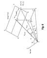
- FIG. 8 is a cross section of the image plane showing the image plane as a single line.
- FIG. 9 shows how to find Limits of current screen in terms of absolute angular coordinates.
- the video display or screen of the camera has four sets of absolute angular coordinates, one set defining each of the screen's corners.
- the privacy zone can be defined by putting a rectangular patch on the screen. The four corners of the rectangular patch have pixel co-ordinates on the screen.
- the privacy zone algorithm converts the pixel co-ordinates to angular co-ordinates.
- the previously defined 3D privacy zone space may have complete overlap, partial overlap or no overlap with the current screen display.
- the masked area will be shown on the screen, and in the last event, the current screen will not have the privacy zone.
- FIG. 3 shows the Pixel and Angular co-ordinates of the four corners of a privacy zone.
- the Pan angle ( ⁇ ) is the azimuth angle of the camera optic axis
- the Tilt angle ( ⁇ ) is the elevation angle of camera optic axis, with respect to the ground plane.
- the Zoom position defines the Horizontal field of view (H FOV ).
- the PTZ dome camera can perform Pan, Tilt, and Zoom operations and the camera can change from the current position, such that a new screen is displayed.
- the known information is the Pan angle, Tilt angle and the Zoom position.
- FIG. 4 illustrates translating the privacy angular coordinates ( ⁇ 1P , ⁇ 1P ), ( ⁇ 2P , ⁇ 2P ), ( ⁇ 3P , ⁇ 3P ), ( ⁇ 4P , ⁇ 4P ) of the four corners of the privacy zone to pixel coordinates (X1,Y1), (X2,Y2), (X3,Y3), (X4,Y4).
- the new screen may not contain one or more of the four corners or points, depending on the camera orientation (i.e. how far the camera sight has moved) with respect to the original privacy zone location.
- FIG. 5 shows a video screen containing a privacy zone or box with height “H” pixels and width “W” pixels.
- the total number of horizontal pixels are shown as Hpix_total and the total number of vertical pixels are shown as Vpix_total.
- the pixel coordinates (X1P,Y1P), (X2P,Y2P), (X3P,Y3P), (X4P,Y4P) of the privacy zone are calculated as follows.
- FIG. 6 shows a 3D view of Image Plane from Camera Focal Point.
- PQRS 610 is the image plane.
- AB 620 is a line drawn from the focal point 600 to the center 630 of the image plane 610 .
- Point C 640 is at the right middle end of the image plane.
- Lines 650 , 660 are the perpendicular projection of points B 630 , C 640 on the horizontal plane 670 .
- Angle BAC 680 is the horizontal field of view, H FOV .
- Tilt angle ⁇ for any point is the angle it makes with the vertical plane
- Pan angle ⁇ is found by dropping a perpendicular line to the horizontal plane and finding the angle the projection makes with the Pan Reference direction.
- point B 630 is the center of the image plane and it has coordinates ( ⁇ , ⁇ ), i.e. the pan angle and tilt angle of the camera.
- FIG. 6 shows angle BAD, i.e., Tilt angle ⁇ , and angle XAD, i.e., Pan angle ⁇ .
- FIG. 6 shows angle CAE, i.e., Tilt angle ⁇ 1
- angle XAE i.e., Pan angle ⁇ 1
- illustrates that angle XAD+angle DAE ⁇ + ⁇ H .
- pan angle tilt angle
- H FOV horizontal field of view
- number of pixels away from center Dpixles which is determined from the pixel coordinates
- ⁇ 1 ⁇ + ⁇ H , where ⁇ is known.
- Equations (9) and (5) above show the relationship of the angular coordinates ( ⁇ 1 , ⁇ 1 ) of the point C in terms of known parameters ( ⁇ , ⁇ ), i.e. the Pan angle and Tilt angle of the camera, and the Horizontal field of view H FOV .
- ⁇ Pan angle and Tilt angle of the camera
- H FOV Horizontal field of view
- FIG. 7 shows an image plane with an arbitrary point (X1,Y1) on the image plane for which we need to find the angular coordinates ( ⁇ 1 , ⁇ 1 ).
- the tilt angle ⁇ at the center gets replaced by ⁇ + ⁇ where ⁇ is the incremental angle from center to reflect that the pixel is at Y1 distance from the center.
- Angle BAC which was equal to H FOV as shown in FIG. 6 , is replaced by the angle EAF or ⁇ 1 .
- FIG. 8 shows a perpendicular line PQ 710 drawn from the focal point P 700 to the center of the image plane Q 720 .
- SQ 730 is the pixels along the vertical field of view V FOV 740 .
- V FOV Aspect ratio*H FOV , where aspect ratio is 3:4 or 0.75.
- the privacy zone can be redrawn on the “new” screen, that is, the screen displayed after the camera moves.
- the privacy zone angular coordinates are known. The location or position of these angular coordinates on the new screen must be found and the privacy zone redrawn, that is, the pixel coordinates corresponding to the angular positions must be determined. Accordingly, the inverse function that can translate any absolute angular coordinates ( ⁇ 1P , ⁇ 1P ) to the corresponding pixel position X1,Y1 on the screen is derived below.
- ⁇ H ⁇ 1 ⁇ (subtracting Pan Angle ⁇ from ⁇ 1 to get ⁇ H ).
- equations 13, 14, 18 and 20 can be used to determine the appropriate location or position of the privacy zone so that a masked area remains masked regardless of the operation of the PTZ dome camera.
- the privacy zone can be updated up to twenty times a second (50 msec).
- One embodiment of the present invention can be implemented using NOD (Next Generation Dome) firmware which is able to define thirty two privacy zones simultaneously, and to display a maximum of eight privacy zones on the screen. If more than eight privacy zones are active, eight are selected to be displayed based on priority.
- the embodiment can operate with a Honeywell NGD Dome which is a high speed dome capable of movement of 480 degrees per second and acceleration of 3840 degrees per second, which translate to a 360 degree angular rotation in less than one second. Accordingly, the privacy zone updates have to be carried out sufficiently quickly, enabling the masking rectangle/quadrilateral to keep track of the object to be covered and not lag behind at any speed. Motion prediction, and zoom prediction can be used to counter the effect of fast movement and zoom. The following steps outline how multiple privacy zones are to be updated in real time in the processor.
- Step 1 at the start of the process, translate the four corners of the current screen to angular coordinates, knowing the present Zoom, Pan, Tilt values.
- the angular resolution used can be of 1/200 th of a degree, i.e., each count corresponds to 0.005 degrees.
- Step 2 check each privacy zone to see if it has any overlap with the screen, such that the privacy zone should be displayed on the screen. If there is an overlap of a particular privacy zone, set the hit_flag of this privacy zone to TRUE.
- the privacy zone ⁇ 1p to ⁇ 4p and ⁇ 1p to ⁇ 4p do not fall within the screen Pan or Tilt gradient limits, the privacy zone does not have overlap with the current screen, and the hit_flag is set to FALSE.
- Step 3 the number of privacy zones having overlap with the current screen is checked. If there are more than eight privacy zones having the hit_flag set to TRUE, then some must be removed as no more than eight privacy zones can be displayed on one screen. The privacy zones having lowest priority are removed by setting the hit_flag to FALSE until only eight privacy zones at any instant of time have the hit_flag equal to TRUE. Then only eight privacy zones will be drawn on the screen. The privacy zones which have hit_flag as TRUE are further considered and the ones with hit_flag as FALSE are not considered anymore for the current screen mapping of privacy zones.
- Step 4 the privacy zones are drawn using pixel maps (and pixel coordinates translated in Step 2). Rectangular fills of each zone is done.
- the following motion equations can be used to do the prediction:
- angles are in radians/second, and velocity is in radian/second 2 and where:
- zoom movement compensation can be done using Zoom look up tables.
Abstract
Description
(X1,Y1)=Inverse Function(Pan Angle,Tilt Angle,Zoom Position,Θ1P,Φ1P).
X1P=X2P=Hpix_total/2−W/2
X4P=X3P=Hpix_total/2+W/2
Y1P=Y4P=Vpix_total/2−H/2
Y2P=Y3P=Vpix_total/2+H/2
Sin H FOV =BC/AC=Dpixels/AC (1)
Cos H FOV =AB/AC=R pixels/AC (2)
Sin Φ=BD/AB=BD/R pixels (3)
Sin Φ1 =CE/AC. (4)
-
- =(R pixels/AC) Sin Φ
- =(Cos HFOV) Sin Φ (substituting from (2)).
Φ1=Sin inv(Cos H FOV Sin Φ) (5)
Sin ΘH =DE/AE=BC/AE=Dpixels/AE. (6)
Cos Φ1 =AE/AC
AE=AC Cos Φ1. (7)
Dpixels/AC=Sin H FOV or AC=Dpixels/Sin H FOV
Sin ΘH =Dpixels/AE=Dpixels/((Dpixels/Sin H FOV)Cos Φ1) or
Sin ΘH=Sin H FOV/Cos Φ1
So that: ΘH=Sin inv(Sin H FOV/Cos Φ1) (8)
Θ1=Θ+Sin inv(Sin H FOV/Cos Φ1)(substituting from (8)). (9)
Φ1=Sin inv(Cos H FOV Sin Φ) (5)
Tan δΦ=QR/PQ=Y1 pixels/PQ and (10)
Tan V FOV =QS/PQ=Vpixels/PQ (11)
Tan δΦ/Tan V FOV =Y1 pixels/Vpixels,
Tan δΦ=Tan VFOV*(Y1 pixels/Vpixels), and solving for δΦ, yields:
δΦ=Tan inv(Tan V FOV*(Y1 pixels/Vpixels)) (12)
δΘ=Tan inv(Tan H FOV*(X1 pixels/Hpixels)) (13)
Θ1=Θ+ΘH=Θ+Sin inv(Sin δΘ1/Cos Φ1) (15)
Φ1=Sin inv(Cos δΘ1 Sin(Φ+δΦ)) (16)
(X1P,Y1P)→(Θ1PΦ1P).
(X2P,Y2P)→(Θ2PΦ2P).
(X3P,Y3P)→(Θ3PΦ3P).
(X4P,Y4P)→(Θ4PΦ4P).
δΘ1=Sin inv(Sin ΘH*Cos Φ1) (17)
X1 pixel Distance=Hpixels*(Tan δΘ/Tan H FOV)
X1 pixel=X1 pixel Distance+X center offset (18)
Sin(Φ+δΦ))=Sin Φ1/Cos δΘ1
(Φ+δΦ))=Sin inv(Sin Φ1/Cos δΘ1)
δΦ=Sin inv(Sin Φ1/Cos δΘ1)−Φ (19)
Y1 pixel Distance=Vpixels*(Tan δΦ/Tan V FOV)
Y1 pixel=Y1 pixel Distance+Y center offset (20)
(Θ1PΦ1P)→(X1P,Y1P)
(Θ2PΦ2P)→(X2P,Y2P)
(Θ3PΦ3P)→(X3P,Y3P)
(Θ4PΦ4P)→(X4P,Y4P).
Claims (17)
δΦ=Tan inv(Tan V FOV*(Y1 pixels/Vpixels))
δΘ=Tan inv(Tan H FOV*(X1 pixels/Hpixels))
Θ1=Θ+Sin inv(Sin δΘ1/Cos Φ1) and
Φ1=Sin inv(Cos δΘ1 Sin(Φ+δΦ)), where
HFOV=Horizontal Field of View
VFOV=0.75*HFOV
Vpixels=one half of the total number of vertical pixels
Hpixels=one half of the total number of horizontal pixels
Θ=azimuth angle of camera optic axis
Φ=elevation angle of camera optic axis.
X1 pixel=(Hpixels*(Tan δΘ/Tan H FOV))+X center offset
Y1 pixel=(Vpixels*(Tan δΦ/Tan V FOV))+Y center offset, where
HFOV=Horizontal Field of View
VFOV=0.75*HFOV
Vpixels=one half of the total number of vertical pixels
Hpixels=one half of the total number of horizontal pixels
Θ=azimuth angle of camera optic axis
Φ=elevation angle of camera optic axis.
δΦ=Tan inv(Tan V FOV*(Y1 pixels/Vpixels))
δΘ=Tan inv(Tan H FOV*(X1 pixels/Hpixels))
Θ1=Θ+Sin inv(Sin δΘ1/Cos Φ1) and
Φ1=Sin inv(Cos δΘ1 Sin(Φ+δΦ)), where
HFOV=Horizontal Field of View
VFOV=0.75*HFOV
Vpixels=one half of the total number of vertical pixels
Hpixels=one half of the total number of horizontal pixels
Θ=azimuth angle of camera optic axis
Φ=elevation angle of camera optic axis.
δΦ=Tan inv(Tan V FOV*(Y1 pixels/Vpixels))
δΘ=Tan inv(Tan H FOV*(X1 pixels/Hpixels))
Θ1=Θ+Sin inv(Sin δΘ1/Cos Φ1) and
Φ1=Sin inv(Cos δΘ1 Sin(Φ+δΦ), where
HFOV=Horizontal Field of View
VFOV=0.75*HFOV
Vpixels=one half of the total number of vertical pixels
Hpixels=one half of the total number of horizontal pixels
Θ=azimuth angle of camera optic axis
Φ=elevation angle of camera optic axis.
X1 pixel=(Hpixels*(Tan δΘ/Tan H FOV))+X center offset
Y1 pixel=(Vpixels*(Tan δΦ/Tan V FOV))+Y center offset, where
HFOV=Horizontal Field of View
VFOV=0.75*HFOV
Vpixels=one half of the total number of vertical pixels
Hpixels=one half of the total number of horizontal pixels
Θ=azimuth angle of camera optic axis
Φ=elevation angle of camera optic axis.
X1 pixel=(Hpixels*(Tan δΘ/Tan H FOV))+X center offset
Y1 pixel=(Vpixels*(Tan δΦ/Tan VFOV))+Y center offset, where
HFOV=Horizontal Field of View
VFOV=0.75*HFOV
Vpixels=one half of the total number of vertical pixels
Hpixels=one half of the total number of horizontal pixels
Θ=azimuth angle of camera optic axis
Φ=elevation angle of camera optic axis.
Priority Applications (5)
| Application Number | Priority Date | Filing Date | Title |
|---|---|---|---|
| US11/777,821 US8098282B2 (en) | 2007-07-13 | 2007-07-13 | Privacy zone algorithm for ptz dome cameras |
| CA2693354A CA2693354A1 (en) | 2007-07-13 | 2008-07-10 | Privacy zone algorithm for ptz dome cameras |
| CN2008801064624A CN101803384B (en) | 2007-07-13 | 2008-07-10 | Privacy zone algorithm for ptz dome cameras |
| PCT/US2008/008483 WO2009011786A1 (en) | 2007-07-13 | 2008-07-10 | Privacy zone algorithm for ptz dome cameras |
| EP08780102.3A EP2174498B1 (en) | 2007-07-13 | 2008-07-10 | Privacy zone algorithm for ptz dome cameras |
Applications Claiming Priority (1)
| Application Number | Priority Date | Filing Date | Title |
|---|---|---|---|
| US11/777,821 US8098282B2 (en) | 2007-07-13 | 2007-07-13 | Privacy zone algorithm for ptz dome cameras |
Publications (2)
| Publication Number | Publication Date |
|---|---|
| US20090015670A1 US20090015670A1 (en) | 2009-01-15 |
| US8098282B2 true US8098282B2 (en) | 2012-01-17 |
Family
ID=40252757
Family Applications (1)
| Application Number | Title | Priority Date | Filing Date |
|---|---|---|---|
| US11/777,821 Active 2030-11-15 US8098282B2 (en) | 2007-07-13 | 2007-07-13 | Privacy zone algorithm for ptz dome cameras |
Country Status (5)
| Country | Link |
|---|---|
| US (1) | US8098282B2 (en) |
| EP (1) | EP2174498B1 (en) |
| CN (1) | CN101803384B (en) |
| CA (1) | CA2693354A1 (en) |
| WO (1) | WO2009011786A1 (en) |
Cited By (8)
| Publication number | Priority date | Publication date | Assignee | Title |
|---|---|---|---|---|
| US20100119177A1 (en) * | 2008-11-07 | 2010-05-13 | Canon Kabushiki Kaisha | Editing apparatus and method |
| US20100296705A1 (en) * | 2007-11-07 | 2010-11-25 | Krysztof Miksa | Method of and arrangement for mapping range sensor data on image sensor data |
| US20120098854A1 (en) * | 2010-10-21 | 2012-04-26 | Canon Kabushiki Kaisha | Display control apparatus and display control method |
| TWI513296B (en) * | 2014-12-16 | 2015-12-11 | Vivotek Inc | Image processing method and image processing device |
| US9319635B2 (en) | 2012-11-30 | 2016-04-19 | Pelco, Inc. | Window blanking for pan/tilt/zoom camera |
| CN106125066A (en) * | 2016-08-10 | 2016-11-16 | 北京艾沃思科技有限公司 | The control system of laser radar and control method |
| US9881171B2 (en) | 2015-11-16 | 2018-01-30 | International Business Machines Corporation | Privacy protecting sensing devices |
| US10447910B2 (en) | 2016-08-04 | 2019-10-15 | International Business Machines Corporation | Camera notification and filtering of content for restricted sites |
Families Citing this family (26)
| Publication number | Priority date | Publication date | Assignee | Title |
|---|---|---|---|---|
| DE102008007199A1 (en) * | 2008-02-01 | 2009-08-06 | Robert Bosch Gmbh | Masking module for a video surveillance system, method for masking selected objects and computer program |
| US20090210147A1 (en) * | 2008-02-20 | 2009-08-20 | Nokia Corporation | Method, Apparatus and Computer Program Product for Map Generation Using Perpendicular Projection to Merge Data |
| CN101615243B (en) * | 2008-06-25 | 2016-03-23 | 汉王科技股份有限公司 | A kind of slope image acquisition device and face identification system |
| JP5471224B2 (en) * | 2009-09-15 | 2014-04-16 | ソニー株式会社 | Imaging system, imaging apparatus, information processing apparatus, and imaging method |
| CN201708855U (en) * | 2009-10-13 | 2011-01-12 | 深圳英飞拓科技股份有限公司 | High-speed ball camera of photoelectric slipping ring transmission video |
| US9794518B2 (en) * | 2010-10-21 | 2017-10-17 | Sensormatic Electronics, LLC | Method and system for converting privacy zone planar images to their corresponding pan/tilt coordinates |
| JP5389879B2 (en) * | 2011-09-20 | 2014-01-15 | 株式会社日立製作所 | Imaging apparatus, surveillance camera, and camera screen masking method |
| DE102012200573A1 (en) * | 2012-01-17 | 2013-07-18 | Robert Bosch Gmbh | Method and device for determining and setting an area to be monitored by a video camera |
| CN103581614A (en) * | 2012-08-01 | 2014-02-12 | 通号通信信息集团有限公司 | Method and system for tracking targets in video based on PTZ |
| JP6231757B2 (en) | 2013-03-27 | 2017-11-15 | キヤノン株式会社 | Imaging apparatus, information processing apparatus, control method therefor, and program |
| GB2512628A (en) * | 2013-04-04 | 2014-10-08 | Sony Corp | Method and apparatus |
| CN104809417A (en) * | 2014-01-29 | 2015-07-29 | 北京三星通信技术研究有限公司 | Method and device for shielding information on display screen and equipment |
| US10083319B2 (en) | 2014-02-24 | 2018-09-25 | Hewlett-Packard Development Company, L.P. | Privacy zone |
| US9679194B2 (en) * | 2014-07-17 | 2017-06-13 | At&T Intellectual Property I, L.P. | Automated obscurity for pervasive imaging |
| CN105791751B (en) * | 2014-12-26 | 2019-05-24 | 浙江大华技术股份有限公司 | A kind of image privacy screen method and ball machine based on ball machine |
| DE112016007291T5 (en) * | 2016-09-30 | 2019-06-19 | Intel Corporation | BRIDGED MICRORASTER FOR A SCREEN WITH ACTIVE SAFETY |
| CN106598078B (en) * | 2016-11-04 | 2020-09-01 | 浙江宇视科技有限公司 | Image processing method and device for pan-tilt camera |
| CN106559656B (en) * | 2016-11-30 | 2020-05-19 | 浙江宇视科技有限公司 | Monitoring picture covering method and device and network camera |
| CN107050859B (en) * | 2017-04-07 | 2020-10-27 | 福州智永信息科技有限公司 | Unity 3D-based method for dragging camera to displace in scene |
| CN107517360B (en) * | 2017-08-01 | 2020-04-14 | 深圳英飞拓科技股份有限公司 | Image area shielding method and device |
| CN107566743B (en) * | 2017-10-30 | 2019-10-11 | 珠海市一微半导体有限公司 | The video monitoring method of mobile robot |
| EP3564900B1 (en) * | 2018-05-03 | 2020-04-01 | Axis AB | Method, device and system for a degree of blurring to be applied to image data in a privacy area of an image |
| CN110460806A (en) * | 2018-05-07 | 2019-11-15 | 厦门脉视数字技术有限公司 | A kind of web camera with holder realizes the algorithm of 3D positioning and privacy screen |
| EP3640903B1 (en) * | 2018-10-18 | 2023-12-27 | IDEMIA Identity & Security Germany AG | Signal dependent video surveillance |
| JP7204449B2 (en) * | 2018-11-29 | 2023-01-16 | キヤノン株式会社 | Control device, imaging device, control method and program |
| CN114245075A (en) * | 2021-12-17 | 2022-03-25 | 杭州视洞科技有限公司 | Interaction method for Gaussian desensitization of camera to privacy area |
Citations (4)
| Publication number | Priority date | Publication date | Assignee | Title |
|---|---|---|---|---|
| US20040119819A1 (en) * | 2002-10-21 | 2004-06-24 | Sarnoff Corporation | Method and system for performing surveillance |
| US20050270371A1 (en) * | 2004-06-02 | 2005-12-08 | Sezai Sablak | Transformable privacy mask for video camera images |
| US20060192853A1 (en) | 2005-02-26 | 2006-08-31 | Samsung Electronics Co., Ltd. | Observation system to display mask area capable of masking privacy zone and method to display mask area |
| US20070115356A1 (en) * | 2005-11-07 | 2007-05-24 | Lg Electronics Inc. | Method and apparatus for masking surveillance video images for privacy protection |
Family Cites Families (2)
| Publication number | Priority date | Publication date | Assignee | Title |
|---|---|---|---|---|
| JP3722653B2 (en) * | 1999-08-31 | 2005-11-30 | 松下電器産業株式会社 | Surveillance camera device and display method of surveillance camera |
| US7161615B2 (en) * | 2001-11-30 | 2007-01-09 | Pelco | System and method for tracking objects and obscuring fields of view under video surveillance |
-
2007
- 2007-07-13 US US11/777,821 patent/US8098282B2/en active Active
-
2008
- 2008-07-10 CN CN2008801064624A patent/CN101803384B/en active Active
- 2008-07-10 WO PCT/US2008/008483 patent/WO2009011786A1/en active Application Filing
- 2008-07-10 CA CA2693354A patent/CA2693354A1/en not_active Abandoned
- 2008-07-10 EP EP08780102.3A patent/EP2174498B1/en active Active
Patent Citations (4)
| Publication number | Priority date | Publication date | Assignee | Title |
|---|---|---|---|---|
| US20040119819A1 (en) * | 2002-10-21 | 2004-06-24 | Sarnoff Corporation | Method and system for performing surveillance |
| US20050270371A1 (en) * | 2004-06-02 | 2005-12-08 | Sezai Sablak | Transformable privacy mask for video camera images |
| US20060192853A1 (en) | 2005-02-26 | 2006-08-31 | Samsung Electronics Co., Ltd. | Observation system to display mask area capable of masking privacy zone and method to display mask area |
| US20070115356A1 (en) * | 2005-11-07 | 2007-05-24 | Lg Electronics Inc. | Method and apparatus for masking surveillance video images for privacy protection |
Cited By (13)
| Publication number | Priority date | Publication date | Assignee | Title |
|---|---|---|---|---|
| US9880010B2 (en) * | 2007-11-07 | 2018-01-30 | Tomtom Global Content B.V. | Method of and arrangement for mapping range sensor data on image sensor data |
| US20100296705A1 (en) * | 2007-11-07 | 2010-11-25 | Krysztof Miksa | Method of and arrangement for mapping range sensor data on image sensor data |
| US8472667B2 (en) * | 2008-11-07 | 2013-06-25 | Canon Kabushiki Kaisha | Editing apparatus and method |
| US20100119177A1 (en) * | 2008-11-07 | 2010-05-13 | Canon Kabushiki Kaisha | Editing apparatus and method |
| US9532008B2 (en) * | 2010-10-21 | 2016-12-27 | Canon Kabushiki Kaisha | Display control apparatus and display control method |
| US20120098854A1 (en) * | 2010-10-21 | 2012-04-26 | Canon Kabushiki Kaisha | Display control apparatus and display control method |
| US9319635B2 (en) | 2012-11-30 | 2016-04-19 | Pelco, Inc. | Window blanking for pan/tilt/zoom camera |
| TWI513296B (en) * | 2014-12-16 | 2015-12-11 | Vivotek Inc | Image processing method and image processing device |
| US9883100B2 (en) | 2014-12-16 | 2018-01-30 | Vivotek Inc. | Image processing method and image processing device for generating rectangular mask in image according to different field of views |
| US9881171B2 (en) | 2015-11-16 | 2018-01-30 | International Business Machines Corporation | Privacy protecting sensing devices |
| US10447910B2 (en) | 2016-08-04 | 2019-10-15 | International Business Machines Corporation | Camera notification and filtering of content for restricted sites |
| CN106125066A (en) * | 2016-08-10 | 2016-11-16 | 北京艾沃思科技有限公司 | The control system of laser radar and control method |
| CN106125066B (en) * | 2016-08-10 | 2018-12-07 | 北京艾沃思科技有限公司 | The control system and control method of laser radar |
Also Published As
| Publication number | Publication date |
|---|---|
| CN101803384A (en) | 2010-08-11 |
| CA2693354A1 (en) | 2009-01-22 |
| US20090015670A1 (en) | 2009-01-15 |
| EP2174498A1 (en) | 2010-04-14 |
| EP2174498B1 (en) | 2020-07-01 |
| EP2174498A4 (en) | 2015-02-25 |
| WO2009011786A1 (en) | 2009-01-22 |
| CN101803384B (en) | 2013-06-05 |
Similar Documents
| Publication | Publication Date | Title |
|---|---|---|
| US8098282B2 (en) | Privacy zone algorithm for ptz dome cameras | |
| US20170094227A1 (en) | Three-dimensional spatial-awareness vision system | |
| CN108474666B (en) | System and method for locating a user in a map display | |
| KR101329470B1 (en) | Image processing device, image processing method, and recording medium containing program thereof | |
| EP1262072B1 (en) | Surveillance apparatus for camera surveillance system | |
| KR101649098B1 (en) | Apparatus and method for rendering using sensor in portable terminal | |
| KR100719120B1 (en) | Observation System to display mask area capable of masking privacy zone and method to display mask area | |
| US20160210785A1 (en) | Augmented reality system and method for positioning and mapping | |
| US10062209B2 (en) | Displaying an object in a panoramic image based upon a line-of-sight direction | |
| EP2413104B1 (en) | Apparatus and method for providing road view | |
| US20190004599A1 (en) | Information processing device, information processing method, and program | |
| US20230316608A1 (en) | Method and apparatus for spatial locating | |
| EP3333808B1 (en) | Information processing device | |
| WO2016163183A1 (en) | Head-mounted display system and computer program for presenting real space surrounding environment of user in immersive virtual space | |
| JP5178454B2 (en) | Vehicle perimeter monitoring apparatus and vehicle perimeter monitoring method | |
| JP5350427B2 (en) | Image processing apparatus, image processing apparatus control method, and program | |
| JP2012216073A (en) | Image processor, image processor control method, and program | |
| US9883092B2 (en) | Mobile receiver unit, method for operating the mobile receiver unit and computer program | |
| CN111309141A (en) | Screen estimation | |
| US10559131B2 (en) | Mediated reality | |
| KR20120005735A (en) | Method and apparatus for presenting location information on augmented reality | |
| CN113973199B (en) | Light-permeable display system and image output method and processing device thereof | |
| Vámossy et al. | PAL Based Localization Using Pyramidal Lucas-Kanade Feature Tracker | |
| JP7040080B2 (en) | Virtual space image presentation system, virtual space image presentation method and program | |
| JP2023039885A (en) | Installation simulation program, installation simulation method and installation simulation device |
Legal Events
| Date | Code | Title | Description |
|---|---|---|---|
| AS | Assignment |
Owner name: HONEYWELL INTERNATIONAL, INC., NEW JERSEY Free format text: ASSIGNMENT OF ASSIGNORS INTEREST;ASSIGNORS:GOPINATH, MANOJ;MARISWAMY, ARATHI;REEL/FRAME:019561/0601 Effective date: 20070710 |
|
| STCF | Information on status: patent grant |
Free format text: PATENTED CASE |
|
| FPAY | Fee payment |
Year of fee payment: 4 |
|
| MAFP | Maintenance fee payment |
Free format text: PAYMENT OF MAINTENANCE FEE, 8TH YEAR, LARGE ENTITY (ORIGINAL EVENT CODE: M1552); ENTITY STATUS OF PATENT OWNER: LARGE ENTITY Year of fee payment: 8 |
|
| MAFP | Maintenance fee payment |
Free format text: PAYMENT OF MAINTENANCE FEE, 12TH YEAR, LARGE ENTITY (ORIGINAL EVENT CODE: M1553); ENTITY STATUS OF PATENT OWNER: LARGE ENTITY Year of fee payment: 12 |