US809798A - Means for controlling overhead electric carriers. - Google Patents
Means for controlling overhead electric carriers. Download PDFInfo
- Publication number
- US809798A US809798A US10390002A US1902103900A US809798A US 809798 A US809798 A US 809798A US 10390002 A US10390002 A US 10390002A US 1902103900 A US1902103900 A US 1902103900A US 809798 A US809798 A US 809798A
- Authority
- US
- United States
- Prior art keywords
- current
- section
- overhead electric
- sections
- electric carriers
- Prior art date
- Legal status (The legal status is an assumption and is not a legal conclusion. Google has not performed a legal analysis and makes no representation as to the accuracy of the status listed.)
- Expired - Lifetime
Links
- 239000000969 carrier Substances 0.000 title description 7
- 239000004020 conductor Substances 0.000 description 9
- 238000009413 insulation Methods 0.000 description 2
Images
Classifications
-
- B—PERFORMING OPERATIONS; TRANSPORTING
- B60—VEHICLES IN GENERAL
- B60L—PROPULSION OF ELECTRICALLY-PROPELLED VEHICLES; SUPPLYING ELECTRIC POWER FOR AUXILIARY EQUIPMENT OF ELECTRICALLY-PROPELLED VEHICLES; ELECTRODYNAMIC BRAKE SYSTEMS FOR VEHICLES IN GENERAL; MAGNETIC SUSPENSION OR LEVITATION FOR VEHICLES; MONITORING OPERATING VARIABLES OF ELECTRICALLY-PROPELLED VEHICLES; ELECTRIC SAFETY DEVICES FOR ELECTRICALLY-PROPELLED VEHICLES
- B60L3/00—Electric devices on electrically-propelled vehicles for safety purposes; Monitoring operating variables, e.g. speed, deceleration or energy consumption
- B60L3/04—Cutting off the power supply under fault conditions
-
- B—PERFORMING OPERATIONS; TRANSPORTING
- B60—VEHICLES IN GENERAL
- B60L—PROPULSION OF ELECTRICALLY-PROPELLED VEHICLES; SUPPLYING ELECTRIC POWER FOR AUXILIARY EQUIPMENT OF ELECTRICALLY-PROPELLED VEHICLES; ELECTRODYNAMIC BRAKE SYSTEMS FOR VEHICLES IN GENERAL; MAGNETIC SUSPENSION OR LEVITATION FOR VEHICLES; MONITORING OPERATING VARIABLES OF ELECTRICALLY-PROPELLED VEHICLES; ELECTRIC SAFETY DEVICES FOR ELECTRICALLY-PROPELLED VEHICLES
- B60L2200/00—Type of vehicles
- B60L2200/26—Rail vehicles
Definitions
- My invention relates to devices used for telpherage, and has for its object to insure the automatic stopping of the carriers as they approach the station.
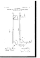
- Figure 1 is a view showing my invention when insulation is used to separate the end connection fromthe main line.
- Fig. 2 is a view showing my invention when resistance is substituted for the insulation.
- A represents the conductor from which the telpher secures its operating-current. This current is supplied by a dynamo B through wires O and D. In this conductor and at or near the stations at each end are placed resistances E E of such a character that the amount of current passing through the sections F F at each end will be sufiicient to move the empty or unloaded telpher, but not suificient to move the same when loaded.
- This wire is provided with a spring-switch H, which is normally open, so that no current passes through said wire. It will be seen that by closing the switch the section F will become energized direct from the dynamo B.
- At the other end of the wire I provide a loop Gr, one end of said loop being attached to the conductor A between the two resistances and the other end to the section F.
- This loop is provided with a spring-switch H of a similar character to the spring-switch H, which is normally open, so that by closing said switch H the section F will be energized by the current passing.
- J is the main switch by which the current may be cut off from the entire system.
- the operation of the device is as follows: Supposing the loaded car to .be at the lefthand station, looking at the drawings, with its trolley on the section F of the conductor, the current flowing through said conductor is not strong enough to move the car. However, on closing the switch H the section F receives current from the dynamo and the car will move, the trolley passing from the section F onto the main conductor A.
- the switch is then allowed to open and the car travels along with the full force of the current.
- the car When, however, the car reaches such a position that its trolley passes onto the section F, it will automatically stop, as the current running through F is not sufficient to move it.
- This stopping may be assisted, if desired, by any of the well-known automatic brake systems, such as that shown in the patent to Glift, No. 688,828, December 17, 1901.
- the telpher reaches the limit of its motion, the current is reversed therethrough by an automatic switch K; but the telpher cannot move toward the other end of the line until its load has been discharged.
- the telpher Will start back automatically, as the current in the section F is just strong enough to move the unloaded telpher.
- the wire F may be energized with sufiicient force to move the loaded telpher by closing the switchH, as heretofore described.
- I may, if I so desire, substitute for the resistances E E insulation-pieces placed at the same points. This changes the system only in one particularnamely, that no. current flows through sections FF normally, so that the car will always be started back by closing the spring-switch H or H. So far as the loaded car is concerned, the action of the system will be precisely the samenamely, that the car will automatically stop when its trolley has passed on to either the section F or F.
- I claim- 1 A means for controlling overhead electric carriers consisting of a main conductor, a section at each end thereof, a resistance between each of said sections and the main line of such a character that insufiicient current flows through said sections to move the loaded carrier, and means for fully energizing said sections, substantially as described.
- a means for controlling overhead electric carriers consisting of a main conductor
Landscapes
- Engineering & Computer Science (AREA)
- Life Sciences & Earth Sciences (AREA)
- Sustainable Development (AREA)
- Sustainable Energy (AREA)
- Power Engineering (AREA)
- Transportation (AREA)
- Mechanical Engineering (AREA)
- Current-Collector Devices For Electrically Propelled Vehicles (AREA)
- Electric Propulsion And Braking For Vehicles (AREA)
Description
'PATBNTED JAN.9
H. M. HARDING.. MEANS FOR CONTROLLING OVERHEAD ELECTRIC CARRIERS.
APPLICATION FILED APB..21, 1902.
ATTORNEYS UNITED s'rarns PATENT @FFICE.
MEANS FOR CONTROLLING OVERHEAD ELECTRIC CARRIERS.
Specification of Letters Patent.
Patented Jan. 9, 1906.
Application filed April 21, 1902. Serial No 103,900-
.TO all whom it 7H/CLZ/ concern:
Be it known that I, HENRY M. HARDING, a citizen of the United States, and a resident of the city, county, and State of New York, have invented certain new and useful Improvements in Means for Controlling Overhead Electric Carriers, of which the following is a specification.
My invention relates to devices used for telpherage, and has for its object to insure the automatic stopping of the carriers as they approach the station.
Figure 1 is a view showing my invention when insulation is used to separate the end connection fromthe main line. Fig. 2 is a view showing my invention when resistance is substituted for the insulation.
A represents the conductor from which the telpher secures its operating-current. This current is supplied by a dynamo B through wires O and D. In this conductor and at or near the stations at each end are placed resistances E E of such a character that the amount of current passing through the sections F F at each end will be sufiicient to move the empty or unloaded telpher, but not suificient to move the same when loaded.
Running from the.junction of the wires 0 D is a wire G, the other end of which is connected with the section F. This wire is provided with a spring-switch H, which is normally open, so that no current passes through said wire. It will be seen that by closing the switch the section F will become energized direct from the dynamo B. At the other end of the wire I provide a loop Gr, one end of said loop being attached to the conductor A between the two resistances and the other end to the section F. This loop is provided with a spring-switch H of a similar character to the spring-switch H, which is normally open, so that by closing said switch H the section F will be energized by the current passing.
through A.
J is the main switch by which the current may be cut off from the entire system.
The operation of the device is as follows: Supposing the loaded car to .be at the lefthand station, looking at the drawings, with its trolley on the section F of the conductor, the current flowing through said conductor is not strong enough to move the car. However, on closing the switch H the section F receives current from the dynamo and the car will move, the trolley passing from the section F onto the main conductor A. The
switch is then allowed to open and the car travels along with the full force of the current. When, however, the car reaches such a position that its trolley passes onto the section F, it will automatically stop, as the current running through F is not sufficient to move it. This stopping may be assisted, if desired, by any of the well-known automatic brake systems, such as that shown in the patent to Glift, No. 688,828, December 17, 1901. Then the telpher reaches the limit of its motion, the current is reversed therethrough by an automatic switch K; but the telpher cannot move toward the other end of the line until its load has been discharged. Upon the discharge of said load the telpher Will start back automatically, as the current in the section F is just strong enough to move the unloaded telpher. If, however, it is desired to load at the section F and carry a return load, the wire F may be energized with sufiicient force to move the loaded telpher by closing the switchH, as heretofore described.
It is sometimes desirable to control the motion of the telpher from either end of the line, or, in other words, to be able to energize the sections F or F from either end of the line. This may be effected by the conductor I, which connects the sections F and F at the points indicated in the drawings. It will be readily seen that by closing either of the switches H or H the sections F and F will become energized with the full force of the current.
I may, if I so desire, substitute for the resistances E E insulation-pieces placed at the same points. This changes the system only in one particularnamely, that no. current flows through sections FF normally, so that the car will always be started back by closing the spring-switch H or H. So far as the loaded car is concerned, the action of the system will be precisely the samenamely, that the car will automatically stop when its trolley has passed on to either the section F or F.
I claim- 1. A means for controlling overhead electric carriers consisting of a main conductor, a section at each end thereof, a resistance between each of said sections and the main line of such a character that insufiicient current flows through said sections to move the loaded carrier, and means for fully energizing said sections, substantially as described.
2. A means for controlling overhead electric carriers consisting of a main conductor,
a section at each end thereof, a resistance between each of said sections and the main line of such a character that insufficient current flows through the said sections to move the loaded carrier, and means for fully energizing said sections from either end of the line, substantially as described.
In testimony whereof I have hereunto set my hand, in the city, county, and State of New York, this 19th day of April, 1902.
4 HENRY M. HARDING.
In presence of E. M. HARMON, J OHN J. RANAGAN.
Priority Applications (1)
| Application Number | Priority Date | Filing Date | Title |
|---|---|---|---|
| US10390002A US809798A (en) | 1902-04-21 | 1902-04-21 | Means for controlling overhead electric carriers. |
Applications Claiming Priority (1)
| Application Number | Priority Date | Filing Date | Title |
|---|---|---|---|
| US10390002A US809798A (en) | 1902-04-21 | 1902-04-21 | Means for controlling overhead electric carriers. |
Publications (1)
| Publication Number | Publication Date |
|---|---|
| US809798A true US809798A (en) | 1906-01-09 |
Family
ID=2878279
Family Applications (1)
| Application Number | Title | Priority Date | Filing Date |
|---|---|---|---|
| US10390002A Expired - Lifetime US809798A (en) | 1902-04-21 | 1902-04-21 | Means for controlling overhead electric carriers. |
Country Status (1)
| Country | Link |
|---|---|
| US (1) | US809798A (en) |
-
1902
- 1902-04-21 US US10390002A patent/US809798A/en not_active Expired - Lifetime
Similar Documents
| Publication | Publication Date | Title |
|---|---|---|
| US809798A (en) | Means for controlling overhead electric carriers. | |
| US631491A (en) | Preventing accidents on drawbridges to electric cars. | |
| US1511253A (en) | Third-rail control | |
| US1112385A (en) | Signal system. | |
| US855601A (en) | Electric railway-switch. | |
| US692136A (en) | Means for regulating speed of cars on overhead electric railways. | |
| US1393404A (en) | Safety device for electrically-operated systems | |
| US2347833A (en) | Railway traffic controlling apparatus | |
| US1543461A (en) | Control of railway trains | |
| US1102550A (en) | Hoisting-conveyance. | |
| US669218A (en) | Electric railway. | |
| US800179A (en) | Electric signaling system. | |
| US869531A (en) | Railway-signaling. | |
| US596182A (en) | Electric railway | |
| US622133A (en) | Automatic switch for railways | |
| US773166A (en) | Electric signal system. | |
| US1429888A (en) | Telpherage system | |
| US723592A (en) | Electric railway. | |
| US700128A (en) | Electric railway. | |
| US615584A (en) | Block-signal system | |
| US1018443A (en) | Block-signaling system for electric railways. | |
| US939154A (en) | Electric controlling and signaling system for railways. | |
| US868911A (en) | Electric-railway system. | |
| US1079451A (en) | Automatic car-stopping device. | |
| US428210A (en) | Electric railway |